open hood NISSAN PICK-UP 1998 Repair Manual
[x] Cancel search | Manufacturer: NISSAN, Model Year: 1998, Model line: PICK-UP, Model: NISSAN PICK-UP 1998Pages: 1659, PDF Size: 53.39 MB
Page 105 of 1659
Body Front End
lWhen removing or installing hood, place a cloth or other padding on hood. This prevents vehicle body
from being scratched.
lBumper fascia is made of plastic. Do not use excessive force and be sure to keep oil away from it.
lHood adjustment: Adjust at hinge portion.
lHood lock adjustment: After adjusting, check hood lock control operation. Apply a coat of grease to hood
locks engaging mechanism.
lHood opener: Do not attempt to bend cable forcibly. Doing so increases effort required to unlock hood.
REMOVAL Ð Front bumper assembly
V1Remove screws securing left and right combination lamps and remove the lamps.
V2Remove clips securing front grille and remove the front grille.
V3Remove bolts securing left and right bumper stays.
V4Remove bolts securing left and right bumper side brackets.
V5Remove bolts securing left and right bumper side stays.
V6Extract bumper assembly.
BODY END
BT-5
Page 178 of 1659
START
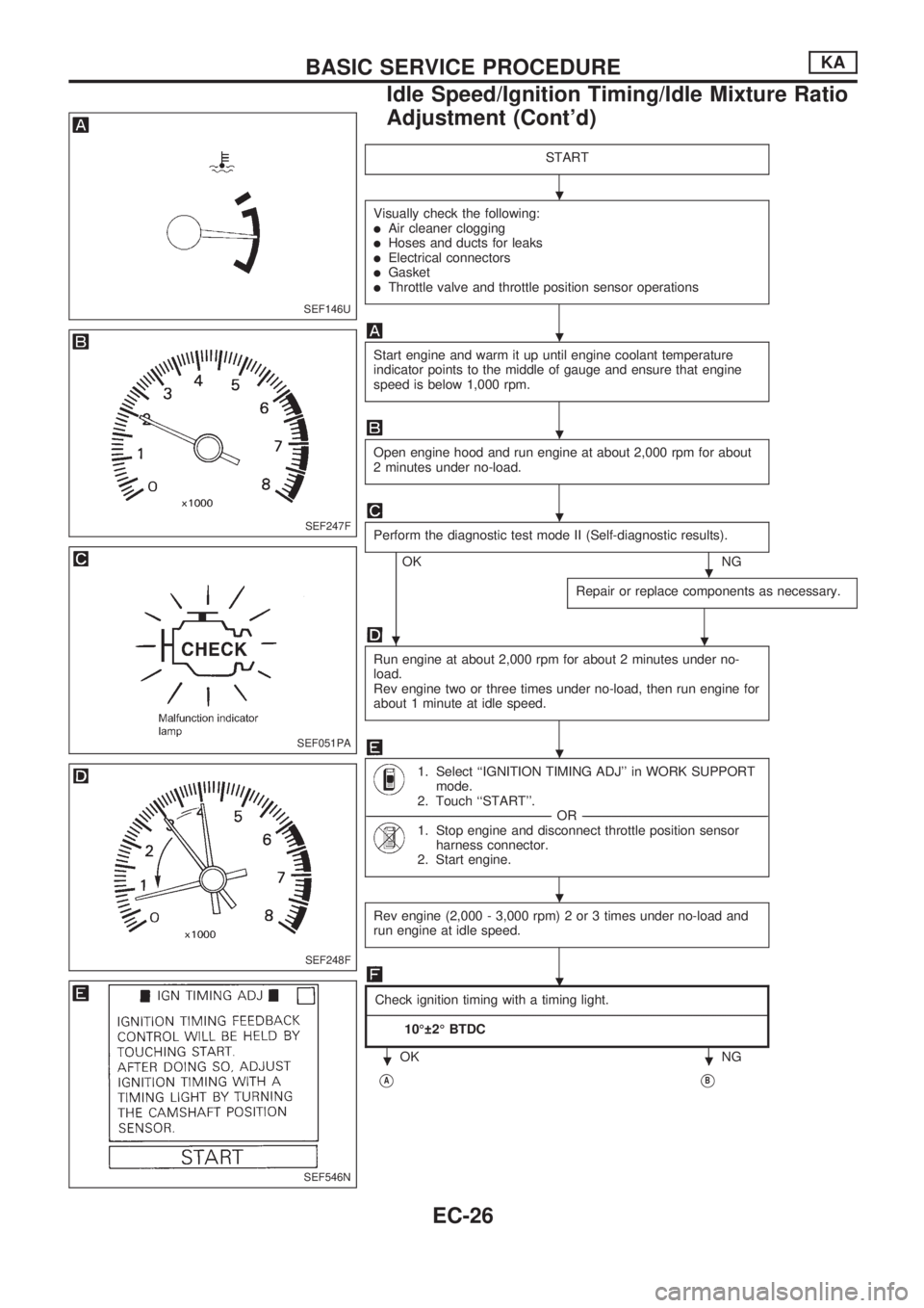
Visually check the following:lAir cleaner clogginglHoses and ducts for leakslElectrical connectorslGasketlThrottle valve and throttle position sensor operations
Start engine and warm it up until engine coolant temperature
indicator points to the middle of gauge and ensure that engine
speed is below 1,000 rpm.
Open engine hood and run engine at about 2,000 rpm for about
2 minutes under no-load.
Perform the diagnostic test mode II (Self-diagnostic results).
OKNG
Repair or replace components as necessary.
.
Run engine at about 2,000 rpm for about 2 minutes under no-
load.
Rev engine two or three times under no-load, then run engine for
about 1 minute at idle speed.
1. Select ``IGNITION TIMING ADJ'' in WORK SUPPORT
mode.
2. Touch ``START''.
----------------------------------------------------------------------------------------------------------------------------------------------------------------------------------------------------------------OR----------------------------------------------------------------------------------------------------------------------------------------------------------------------------------------------------------------
1. Stop engine and disconnect throttle position sensor
harness connector.
2. Start engine.
Rev engine (2,000 - 3,000 rpm) 2 or 3 times under no-load and
run engine at idle speed.
Check ignition timing with a timing light.
---------------------------------------------------------------------------------------------------------------------------------------------------------------------------------------------------------------------------------------------------------------------------------------------------------------------------------------------------------------------------------------------------------------------------------------------------------------------
10É 2É BTDC
OK NG
VAVB
SEF146U
SEF247F
SEF051PA
SEF248F
SEF546N
.
.
.
.
.
.
.
.
.
..
BASIC SERVICE PROCEDUREKA
Idle Speed/Ignition Timing/Idle Mixture Ratio
Adjustment (Cont'd)
EC-26
Page 184 of 1659
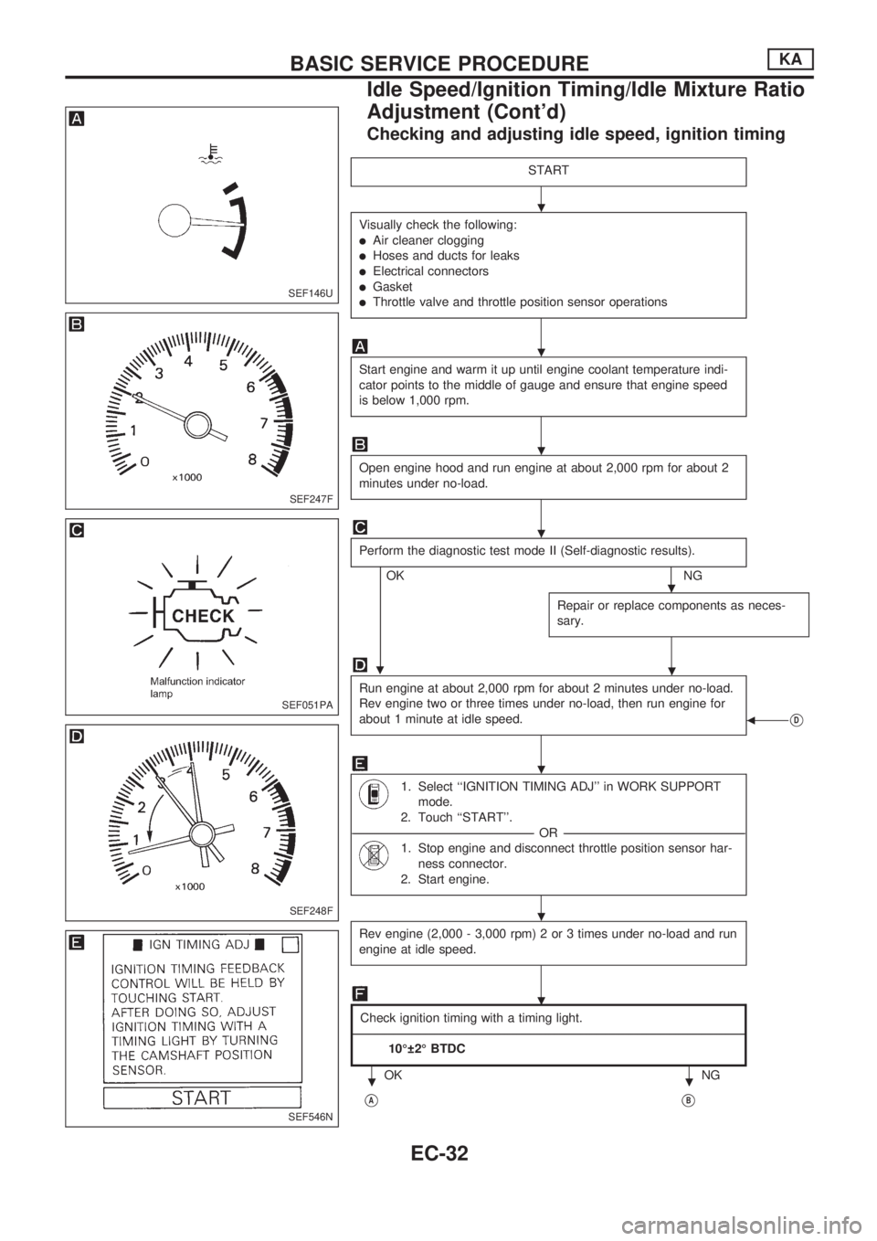
Checking and adjusting idle speed, ignition timing
START
Visually check the following:
lAir cleaner clogging
lHoses and ducts for leaks
lElectrical connectors
lGasket
lThrottle valve and throttle position sensor operations
Start engine and warm it up until engine coolant temperature indi-
cator points to the middle of gauge and ensure that engine speed
is below 1,000 rpm.
Open engine hood and run engine at about 2,000 rpm for about 2
minutes under no-load.
Perform the diagnostic test mode II (Self-diagnostic results).
OKNG
Repair or replace components as neces-
sary.
.
Run engine at about 2,000 rpm for about 2 minutes under no-load.
Rev engine two or three times under no-load, then run engine for
about 1 minute at idle speed.
bVD
1. Select ``IGNITION TIMING ADJ'' in WORK SUPPORT
mode.
2. Touch ``START''.
-----------------------------------------------------------------------------------------------------------------------------------------------------------------------------------------------------------------------OR -----------------------------------------------------------------------------------------------------------------------------------------------------------------------------------------------------------------------
1. Stop engine and disconnect throttle position sensor har-
ness connector.
2. Start engine.
Rev engine (2,000 - 3,000 rpm) 2 or 3 times under no-load and run
engine at idle speed.
Check ignition timing with a timing light.
------------------------------------------------------------------------------------------------------------------------------------------------------------------------------------------------------------------------------------------------------------------------------------------------------------------------------------------------------------------------------------------------------------------------------------------------------------------------------------
10É 2É BTDC
OK NG
VAVB
SEF146U
SEF247F
SEF051PA
SEF248F
SEF546N
.
.
.
.
.
.
.
.
.
..
BASIC SERVICE PROCEDUREKA
Idle Speed/Ignition Timing/Idle Mixture Ratio
Adjustment (Cont'd)
EC-32
Page 210 of 1659
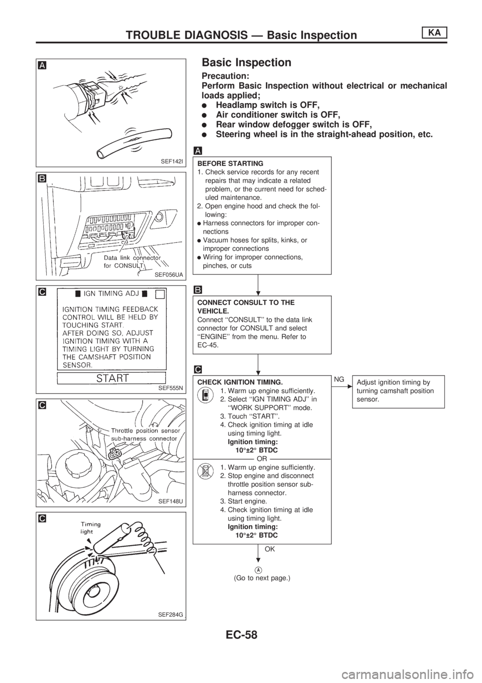
Basic Inspection
Precaution:
Perform Basic Inspection without electrical or mechanical
loads applied;
lHeadlamp switch is OFF,
lAir conditioner switch is OFF,
lRear window defogger switch is OFF,
lSteering wheel is in the straight-ahead position, etc.
BEFORE STARTING
1. Check service records for any recent
repairs that may indicate a related
problem, or the current need for sched-
uled maintenance.
2. Open engine hood and check the fol-
lowing:
lHarness connectors for improper con-
nections
lVacuum hoses for splits, kinks, or
improper connections
lWiring for improper connections,
pinches, or cuts
CONNECT CONSULT TO THE
VEHICLE.
Connect ``CONSULT'' to the data link
connector for CONSULT and select
``ENGINE'' from the menu. Refer to
EC-45.
CHECK IGNITION TIMING.
1. Warm up engine sufficiently.
2. Select ``IGN TIMING ADJ'' in
``WORK SUPPORT'' mode.
3. Touch ``START''.
4. Check ignition timing at idle
using timing light.
Ignition timing:
10É 2É BTDC
----------------------------------------------------------------------------------------------------------------------------------OR----------------------------------------------------------------------------------------------------------------------------------
1. Warm up engine sufficiently.
2. Stop engine and disconnect
throttle position sensor sub-
harness connector.
3. Start engine.
4. Check ignition timing at idle
using timing light.
Ignition timing:
10É 2É BTDC
OK
cNG
Adjust ignition timing by
turning camshaft position
sensor.
VA
(Go to next page.)
SEF142I
SEF056UA
SEF555N
SEF148U
SEF284G
.
.
.
TROUBLE DIAGNOSIS Ð Basic InspectionKA
EC-58
Page 897 of 1659
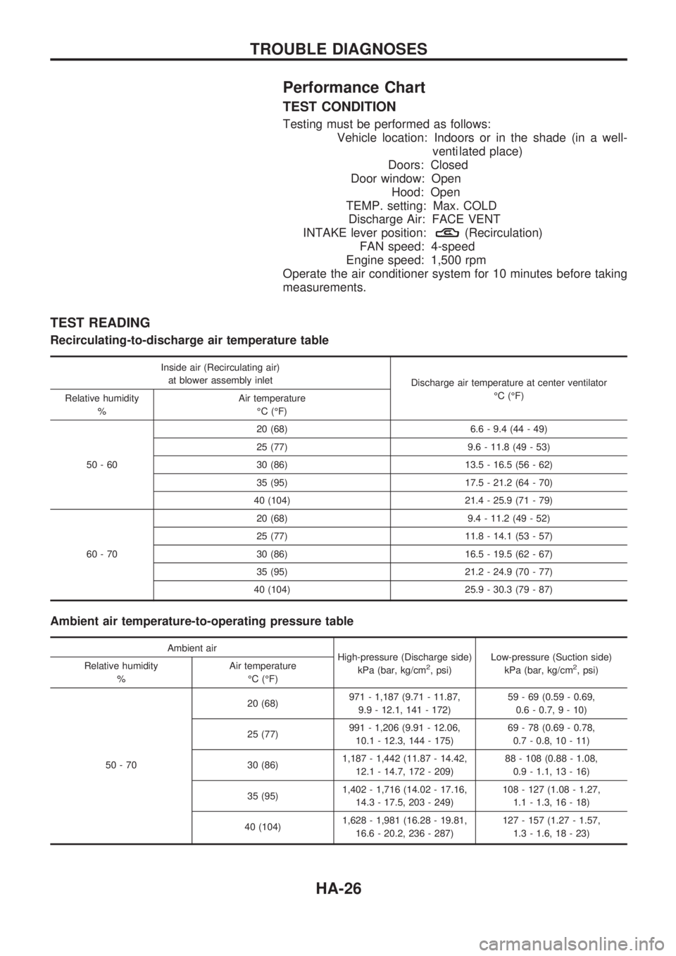
Performance Chart
TEST CONDITION
Testing must be performed as follows:
Vehicle location: Indoors or in the shade (in a well-
venti lated place)
Doors: Closed
Door window: Open
Hood: Open
TEMP. setting: Max. COLD
Discharge Air: FACE VENT
INTAKE lever position:
(Recirculation)
FAN speed: 4-speed
Engine speed: 1,500 rpm
Operate the air conditioner system for 10 minutes before taking
measurements.
TEST READING
Recirculating-to-discharge air temperature table
Inside air (Recirculating air)
at blower assembly inlet
Discharge air temperature at center ventilator
ÉC (ÉF)
Relative humidity
%Air temperature
ÉC (ÉF)
50-6020 (68) 6.6 - 9.4 (44 - 49)
25 (77) 9.6 - 11.8 (49 - 53)
30 (86) 13.5 - 16.5 (56 - 62)
35 (95) 17.5 - 21.2 (64 - 70)
40 (104) 21.4 - 25.9 (71 - 79)
60-7020 (68) 9.4 - 11.2 (49 - 52)
25 (77) 11.8 - 14.1 (53 - 57)
30 (86) 16.5 - 19.5 (62 - 67)
35 (95) 21.2 - 24.9 (70 - 77)
40 (104) 25.9 - 30.3 (79 - 87)
Ambient air temperature-to-operating pressure table
Ambient air
High-pressure (Discharge side)
kPa (bar, kg/cm
2, psi)Low-pressure (Suction side)
kPa (bar, kg/cm2, psi) Relative humidity
%Air temperature
ÉC (ÉF)
50-7020 (68)971 - 1,187 (9.71 - 11.87,
9.9 - 12.1, 141 - 172)59 - 69 (0.59 - 0.69,
0.6 - 0.7, 9 - 10)
25 (77)991 - 1,206 (9.91 - 12.06,
10.1 - 12.3, 144 - 175)69 - 78 (0.69 - 0.78,
0.7 - 0.8, 10 - 11)
30 (86)1,187 - 1,442 (11.87 - 14.42,
12.1 - 14.7, 172 - 209)88 - 108 (0.88 - 1.08,
0.9 - 1.1, 13 - 16)
35 (95)1,402 - 1,716 (14.02 - 17.16,
14.3 - 17.5, 203 - 249)108 - 127 (1.08 - 1.27,
1.1 - 1.3, 16 - 18)
40 (104)1,628 - 1,981 (16.28 - 19.81,
16.6 - 20.2, 236 - 287)127 - 157 (1.27 - 1.57,
1.3 - 1.6, 18 - 23)
TROUBLE DIAGNOSES
HA-26
Page 977 of 1659
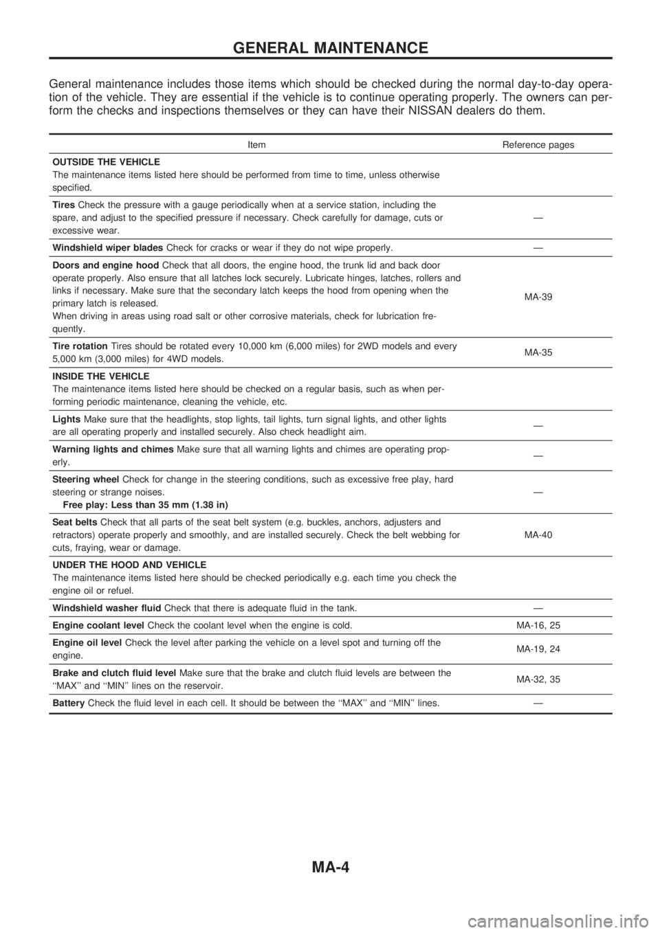
General maintenance includes those items which should be checked during the normal day-to-day opera-
tion of the vehicle. They are essential if the vehicle is to continue operating properly. The owners can per-
form the checks and inspections themselves or they can have their NISSAN dealers do them.
Item Reference pages
OUTSIDE THE VEHICLE
The maintenance items listed here should be performed from time to time, unless otherwise
specified.
TiresCheck the pressure with a gauge periodically when at a service station, including the
spare, and adjust to the specified pressure if necessary. Check carefully for damage, cuts or
excessive wear.Ð
Windshield wiper bladesCheck for cracks or wear if they do not wipe properly. Ð
Doors and engine hoodCheck that all doors, the engine hood, the trunk lid and back door
operate properly. Also ensure that all latches lock securely. Lubricate hinges, latches, rollers and
links if necessary. Make sure that the secondary latch keeps the hood from opening when the
primary latch is released.
When driving in areas using road salt or other corrosive materials, check for lubrication fre-
quently.MA-39
Tire rotationTires should be rotated every 10,000 km (6,000 miles) for 2WD models and every
5,000 km (3,000 miles) for 4WD models.MA-35
INSIDE THE VEHICLE
The maintenance items listed here should be checked on a regular basis, such as when per-
forming periodic maintenance, cleaning the vehicle, etc.
LightsMake sure that the headlights, stop lights, tail lights, turn signal lights, and other lights
are all operating properly and installed securely. Also check headlight aim.Ð
Warning lights and chimesMake sure that all warning lights and chimes are operating prop-
erly.Ð
Steering wheelCheck for change in the steering conditions, such as excessive free play, hard
steering or strange noises.
Free play: Less than 35 mm (1.38 in)Ð
Seat beltsCheck that all parts of the seat belt system (e.g. buckles, anchors, adjusters and
retractors) operate properly and smoothly, and are installed securely. Check the belt webbing for
cuts, fraying, wear or damage.MA-40
UNDER THE HOOD AND VEHICLE
The maintenance items listed here should be checked periodically e.g. each time you check the
engine oil or refuel.
Windshield washer fluidCheck that there is adequate fluid in the tank. Ð
Engine coolant levelCheck the coolant level when the engine is cold. MA-16, 25
Engine oil levelCheck the level after parking the vehicle on a level spot and turning off the
engine.MA-19, 24
Brake and clutch fluid levelMake sure that the brake and clutch fluid levels are between the
``MAX'' and ``MIN'' lines on the reservoir.MA-32, 35
BatteryCheck the fluid level in each cell. It should be between the ``MAX'' and ``MIN'' lines. Ð
GENERAL MAINTENANCE
MA-4
Page 1014 of 1659
Checking Body Corrosion
Visually check the body sheet metal panel for corrosion, paint damage (scratches, chipping, rubbing, etc.)
or damage to the anti-corrosion materials. In particular, check the following locations.
Hemmed portion
Hood front end, door lower end, trunk lid rear end, etc.
Panel joint
Side sill of rear fender and center pillar, rear wheel housing of rear fender, around strut tower in engine
compartment, etc.
Panel edge
Trunk lid opening, sunroof opening, fender wheelarch flange, fuel filler lid flange, around holes in panel, etc.
Parts contact
Waist molding, windshield molding, bumper, etc.
Protectors
Damage or condition of mudguard, fender protector, chipping protector, etc.
Anti-corrosion materials
Damage or separation of anti-corrosion materials under the body.
Drain holes
Condition of drain holes at door and side sill.
When repairing corroded areas, refer to the Corrosion Repair Manual.
CHASSIS AND BODY MAINTENANCE
MA-41