check oil NISSAN PICK-UP 1998 Manual Online
[x] Cancel search | Manufacturer: NISSAN, Model Year: 1998, Model line: PICK-UP, Model: NISSAN PICK-UP 1998Pages: 1659, PDF Size: 53.39 MB
Page 1007 of 1659
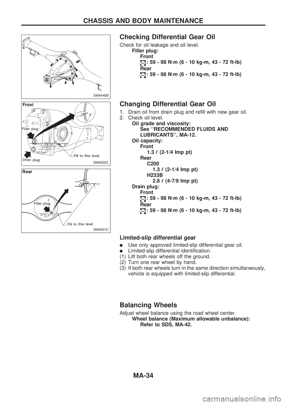
Checking Differential Gear Oil
Check for oil leakage and oil level.
Filler plug:
Front
: 59 - 98 N´m (6 - 10 kg-m, 43 - 72 ft-lb)
Rear
: 59 - 98 N´m (6 - 10 kg-m, 43 - 72 ft-lb)
Changing Differential Gear Oil
1. Drain oil from drain plug and refill with new gear oil.
2. Check oil level.
Oil grade and viscosity:
See ``RECOMMENDED FLUIDS AND
LUBRICANTS'', MA-12.
Oil capacity:
Front
1.3ø(2-1/4 Imp pt)
Rear
C200
1.3ø(2-1/4 Imp pt)
H233B
2.8ø(4-7/8 Imp pt)
Drain plug:
Front
: 59 - 98 N´m (6 - 10 kg-m, 43 - 72 ft-lb)
Rear
: 59 - 98 N´m (6 - 10 kg-m, 43 - 72 ft-lb)
Limited-slip differential gear
lUse only approved limited-slip differential gear oil.
lLimited-slip differential identification.
(1) Lift both rear wheels off the ground.
(2) Turn one rear wheel by hand.
(3) If both rear wheels turn in the same direction simultaneously,
vehicle is equipped with limited-slip differential.
Balancing Wheels
Adjust wheel balance using the road wheel center.
Wheel balance (Maximum allowable unbalance):
Refer to SDS, MA-42.
SMA440B
SMA632C
SMA631C
CHASSIS AND BODY MAINTENANCE
MA-34
Page 1011 of 1659
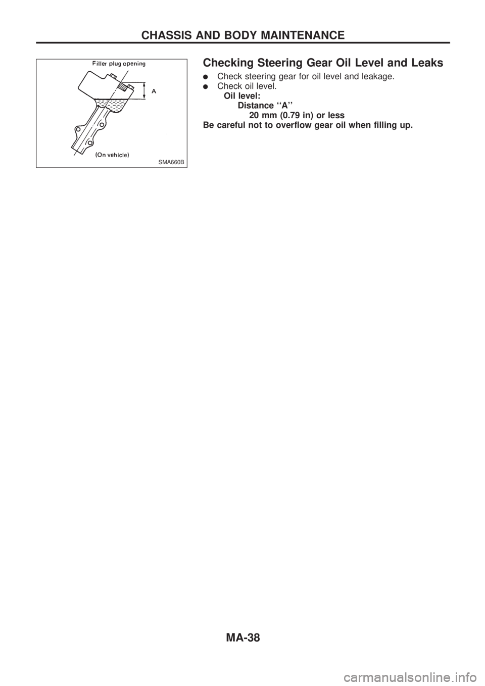
Checking Steering Gear Oil Level and Leaks
lCheck steering gear for oil level and leakage.
lCheck oil level.
Oil level:
Distance ``A''
20 mm (0.79 in) or less
Be careful not to overflow gear oil when filling up.
SMA660B
CHASSIS AND BODY MAINTENANCE
MA-38
Page 1016 of 1659
MANUALTRANSAXLESECTION
MT
CONTENTS
FS5W71C
PREPARATION ......................................................... 1
Special Service Tools ............................................ 1
Commercial Service Tools ..................................... 3
FS5R30A
PREPARATION......................................................... 4
Special Service Tools ............................................ 4
Commercial Service Tool....................................... 5
FS5W71C
DESCRIPTION........................................................... 6
Cross-sectional View - 2WD Model ....................... 6
Cross-sectional View - 4WD Model ....................... 7
FS5R30A
DESCRIPTION........................................................... 8
Cross-sectional View - 4WD Model ....................... 8
FS5W71C
ON-VEHICLE SERVICE ............................................ 9
Replacing Rear Oil Seal - 2WD Model.................. 9
Position Switch Check ........................................... 9
FS5R30A
ON-VEHICLE SERVICE .......................................... 10
Position Switch Check - 4WD Model................... 10
FS5W71C & FS5R30A
REMOVAL AND INSTALLATION ........................... 11
Removal ............................................................... 11 Installation ............................................................ 12
FS5W71C
MAJOR OVERHAUL ............................................... 14
Case Components ............................................... 14
Gear Components - 2WD Model ......................... 15
Gear Components - 4WD Model ......................... 16
Shift Control Components - 2WD Model ............. 17
Shift Control Components - 4WD Model ............. 18
DISASSEMBLY ........................................................ 19
Case Components ............................................... 19
Shift Control Components.................................... 20
Gear Components................................................ 20
INSPECTION ............................................................ 23
Shift Control Components.................................... 23
Gear Components................................................ 23
ASSEMBLY .............................................................. 25
Gear Components................................................ 25
Shift Control Components.................................... 31
Case Components ............................................... 32
FS5R30A
MAJOR OVERHAUL ............................................... 35
Case Components ............................................... 35
Gear Components................................................ 36
Shift Control Components.................................... 38
DISASSEMBLY ........................................................ 39
Case Components ............................................... 39
Shift Control Components.................................... 40
Gear Components................................................ 41
INSPECTION ............................................................ 45
Shift Control Components.................................... 45
Gear Components................................................ 45
MT
Page 1026 of 1659
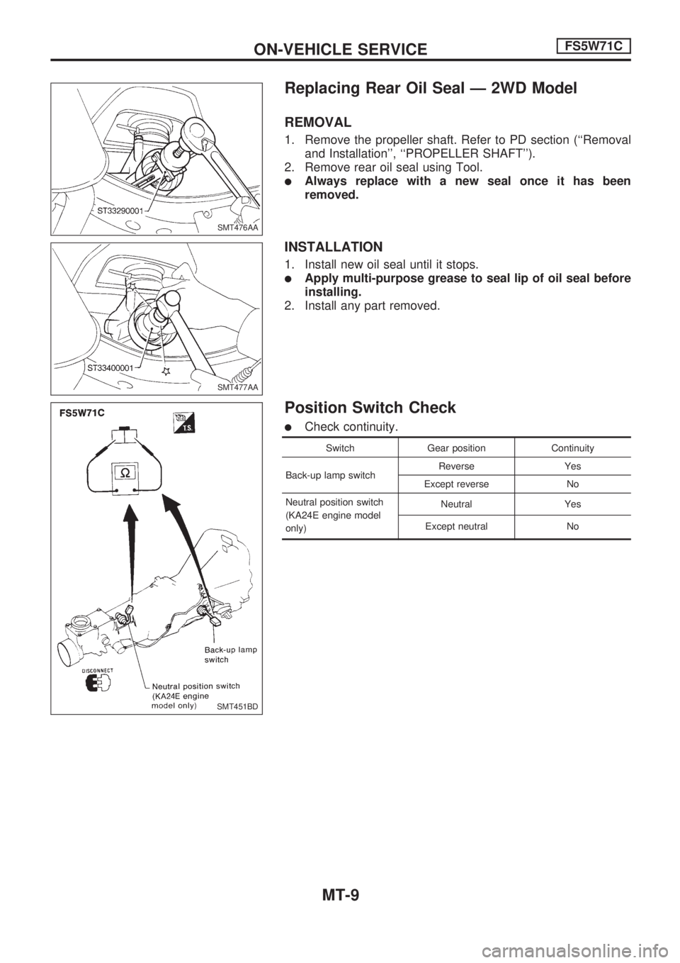
Replacing Rear Oil Seal Ð 2WD Model
REMOVAL
1. Remove the propeller shaft. Refer to PD section (``Removal
and Installation'', ``PROPELLER SHAFT'').
2. Remove rear oil seal using Tool.
lAlways replace with a new seal once it has been
removed.
INSTALLATION
1. Install new oil seal until it stops.
lApply multi-purpose grease to seal lip of oil seal before
installing.
2. Install any part removed.
Position Switch Check
lCheck continuity.
Switch Gear position Continuity
Back-up lamp switchReverse Yes
Except reverse No
Neutral position switch
(KA24E engine model
only)Neutral Yes
Except neutral No
SMT476AA
SMT477AA
SMT451BD
ON-VEHICLE SERVICEFS5W71C
MT-9
Page 1037 of 1659
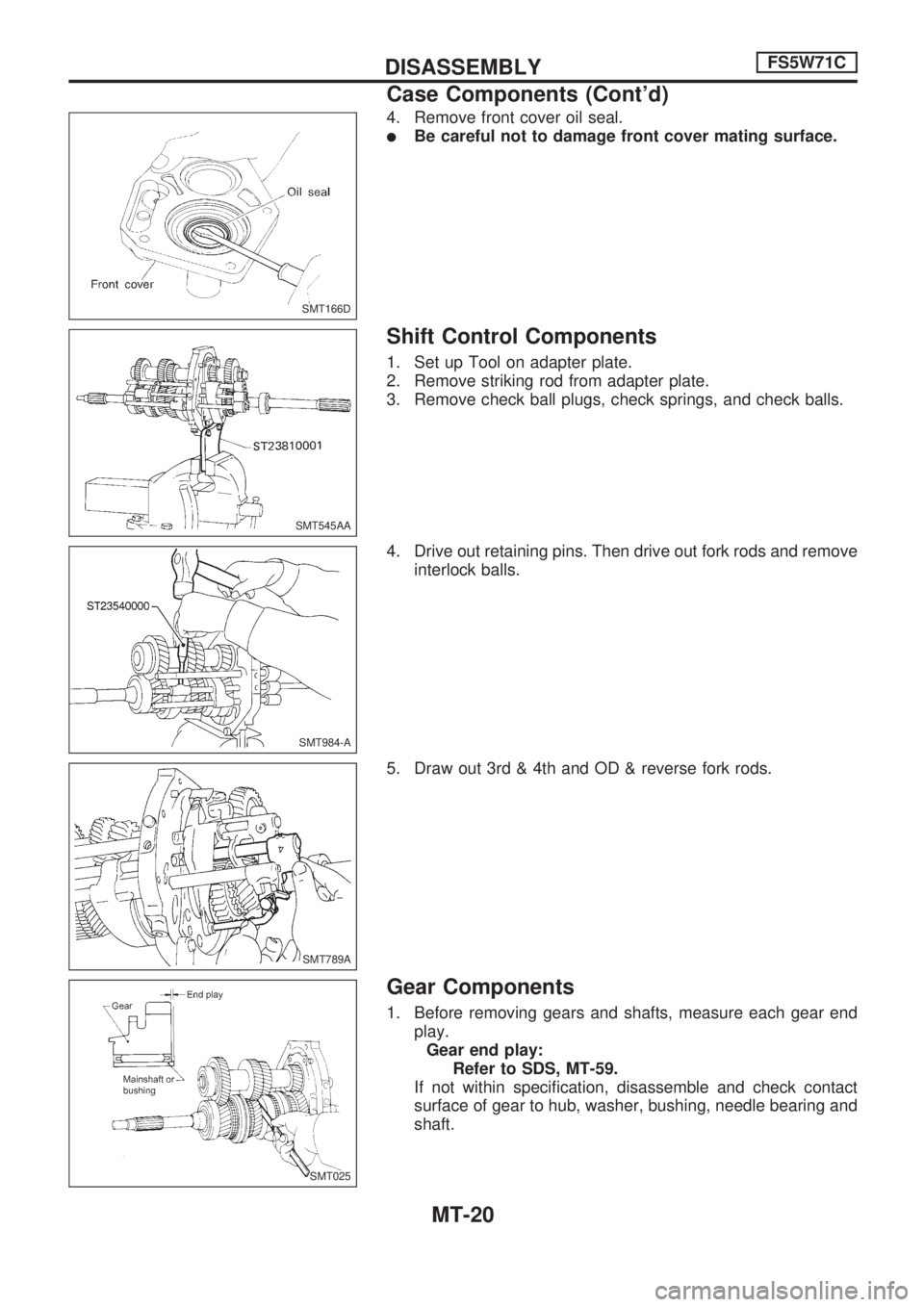
4. Remove front cover oil seal.
lBe careful not to damage front cover mating surface.
Shift Control Components
1. Set up Tool on adapter plate.
2. Remove striking rod from adapter plate.
3. Remove check ball plugs, check springs, and check balls.
4. Drive out retaining pins. Then drive out fork rods and remove
interlock balls.
5. Draw out 3rd & 4th and OD & reverse fork rods.
Gear Components
1. Before removing gears and shafts, measure each gear end
play.
Gear end play:
Refer to SDS, MT-59.
If not within specification, disassemble and check contact
surface of gear to hub, washer, bushing, needle bearing and
shaft.
SMT166D
SMT545AA
SMT984-A
SMT789A
SMT025
DISASSEMBLYFS5W71C
Case Components (Cont'd)
MT-20
Page 1072 of 1659
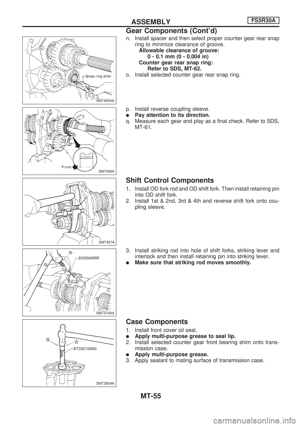
n. Install spacer and then select proper counter gear rear snap
ring to minimize clearance of groove.
Allowable clearance of groove:
0 - 0.1 mm (0 - 0.004 in)
Counter gear rear snap ring:
Refer to SDS, MT-62.
o. Install selected counter gear rear snap ring.
p. Install reverse coupling sleeve.
lPay attention to its direction.
q. Measure each gear end play as a final check. Refer to SDS,
MT-61.
Shift Control Components
1. Install OD fork rod and OD shift fork. Then install retaining pin
into OD shift fork.
2. Install 1st & 2nd, 3rd & 4th and reverse shift fork onto cou-
pling sleeve.
3. Install striking rod into hole of shift forks, striking lever and
interlock and then install retaining pin into striking lever.
lMake sure that striking rod moves smoothly.
Case Components
1. Install front cover oil seal.
lApply multi-purpose grease to seal lip.
2. Install selected counter gear front bearing shim onto trans-
mission case.
lApply multi-purpose grease.
3. Apply sealant to mating surface of transmission case.
SMT455AA.SMT455AA
SMT456A
SMT457A.SMT457A
SMT374AA.SMT374AA
SMT393AA
ASSEMBLYFS5R30A
Gear Components (Cont'd)
MT-55
Page 1086 of 1659
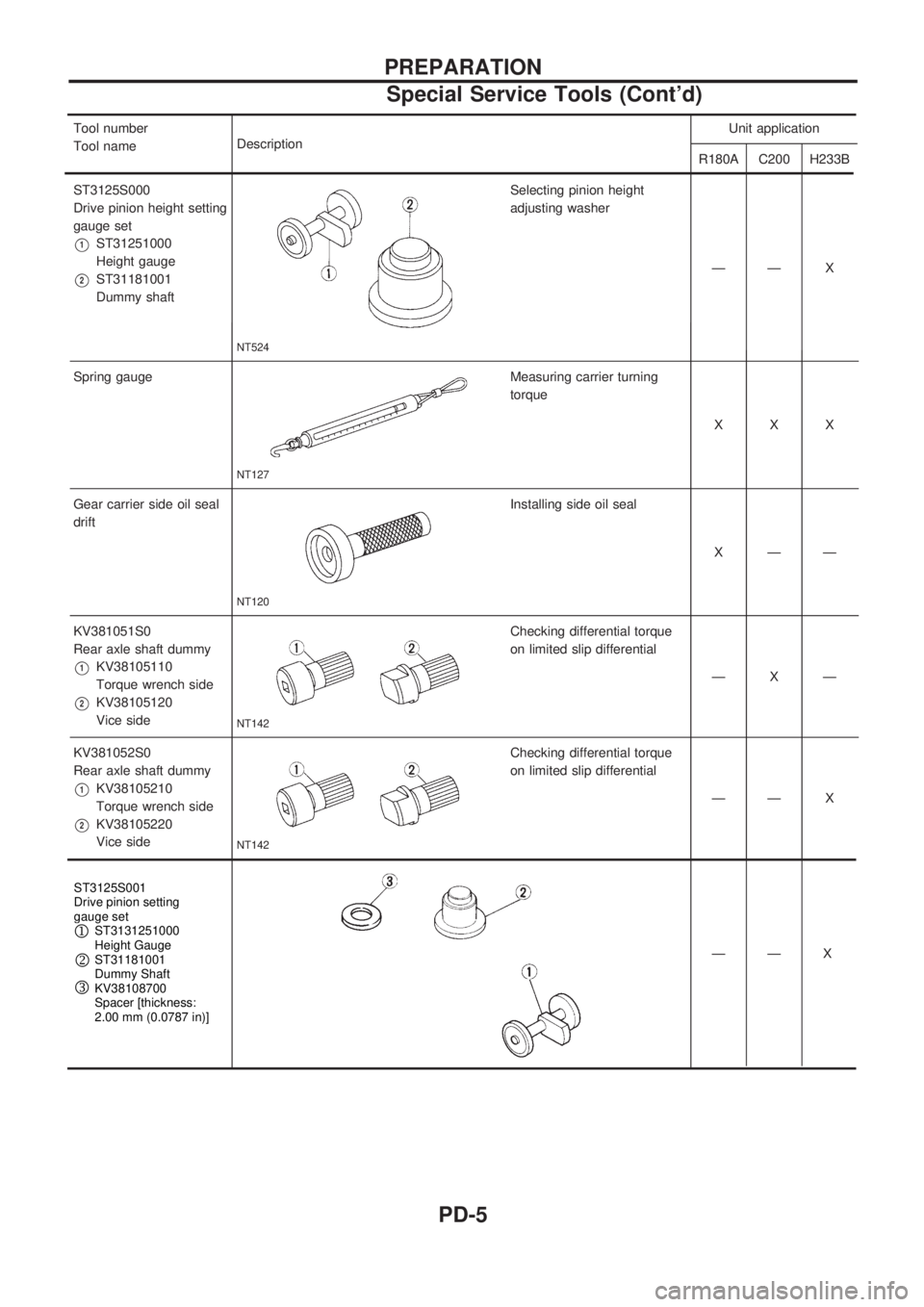
Tool number
Tool nameDescription Unit application
R180A C200 H233B
ST3125S000
Drive pinion height setting
gauge set
V1ST31251000
Height gauge
V2ST31181001
Dummy shaft
NT524
Selecting pinion height
adjusting washer
ÐÐ X
Spring gauge
NT127
Measuring carrier turning
torque XXX
Gear carrier side oil seal
drift
NT120
Installing side oil seal XÐÐ
KV381051S0
Rear axle shaft dummy
V1KV38105110
Torque wrench side
V2KV38105120
Vice side
NT142
Checking differential torque
on limited slip differential ÐXÐ
KV381052S0
Rearaxleshaftdummy
V1KV38105210
Torque wrench side
V2KV38105220
Vice side
NT142
Checking differential torque
on limited slip differential ÐÐX
——X
—X
PREPARATION
Special Service Tools (Cont'd)
PD-5
Page 1089 of 1659
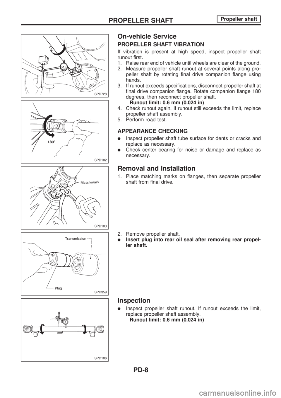
On-vehicle Service
PROPELLER SHAFT VIBRATION
If vibration is present at high speed, inspect propeller shaft
runout first.
1. Raise rear end of vehicle until wheels are clear of the ground.
2. Measure propeller shaft runout at several points along pro-
peller shaft by rotating final drive companion flange using
hands.
3. If runout exceeds specifications, disconnect propeller shaft at
final drive companion flange. Rotate companion flange 180
degrees, then reconnect propeller shaft.
Runout limit: 0.6 mm (0.024 in)
4. Check runout again. If runout still exceeds the limit, replace
propeller shaft assembly.
5. Perform road test.
APPEARANCE CHECKING
lInspect propeller shaft tube surface for dents or cracks and
replace as necessary.
lCheck center bearing for noise or damage and replace as
necessary.
Removal and Installation
1. Place matching marks on flanges, then separate propeller
shaft from final drive.
2. Remove propeller shaft.
lInsert plug into rear oil seal after removing rear propel-
ler shaft.
Inspection
lInspect propeller shaft runout. If runout exceeds the limit,
replace propeller shaft assembly.
Runout limit: 0.6 mm (0.024 in)
SPD728
SPD102
SPD103
SPD359
SPD106
PROPELLER SHAFTPropeller shaft
PD-8
Page 1107 of 1659

Tooth Contact
Gear tooth contact pattern check is necessary to verify correct
relationship between ring gear and drive pinion.
Hypoid gear sets which are not positioned properly may be
noisy, or have short life, or both. With a pattern check, the most
desirable contact for low noise level and long life can be assured.
1. Thoroughly clean ring gear and drive pinion teeth.
2. Sparingly apply a mixture of powdered ferric oxide and oil or
equivalent to 3 or 4 teeth of ring gear drive side.
3. Hold companion flange steady and rotate the ring gear in
both directions.
SPD357
SPD653
SPD007
ADJUSTMENTR180A
PD-26
Page 1108 of 1659

Extension Tube and Differential Side Shaft
1. Measure rear axle bearing end play.
Rear axle bearing end play (A þ B):
0.1 mm (0.004 in) or less
The end play can be adjusted with bearing adjusting shim.
Available bearing adjusting shims:
Refer to SDS, PD-78.
2. Install grease seal.
3. Install extension tube retainer, rear axle bearing and rear
axle shaft bearing collar on differential side shaft.
4. Install differential side shaft assembly into extension tube.
Differential Case
1. Measure clearance between side gear thrust washer and
differential case.
Clearance between side gear thrust washer
and differential case (A þ B):
Less than 0.15 mm (0.0059 in)
The clearance can be adjusted with side gear thrust washer.
Available side gear thrust washers:
Refer to SDS, PD-78.
2. Apply gear oil to gear tooth surfaces and thrust surfaces and
check to see they turn properly.
SPD433A
SPD654
SPD655
SPD656
ASSEMBLYR180A
PD-27