dimensions NISSAN PICK-UP 1998 User Guide
[x] Cancel search | Manufacturer: NISSAN, Model Year: 1998, Model line: PICK-UP, Model: NISSAN PICK-UP 1998Pages: 1659, PDF Size: 53.39 MB
Page 870 of 1659
Throttle body ................................................. EM-9
Throttle position sensor (TPS)................... EC-113
Throwout bearing - See Clutch release
bearing........................................................ CL-9
Tie-rod .......................................................... ST-37
Tie-rod ball joints.......................................... ST-37
Tightening torque of standard bolts .............. GI-54
Timing chain ................................................ EM-13
Timing gear ................................................. EM-89
Tire rotation ................................................. MA-35
Tire size ........................................................ GI-46
Tooth contact (R180A) ................................ PD-26
Tooth contact (C200) ................................... PD-49
Tooth contact (H233B) ................................ PD-70
Torsion bar spring ........................................ FA-28
Tow truck towing ........................................... GI-51
Towing point.................................................. GI-53
Transfer case ................................................. TF-8
Transfer oil replacement ............................. MA-33
Transfer serial number.................................. GI-43
Transmission case (M/T) (FS5R30A).......... MT-35
Transmission case (M/T) (FS5W71C)......... MT-14
Transmission serial number.......................... GI-43
Tread - FR&RR (Dimensions) ...................... GI-44
Trim .............................................................. BT-15
Triple pressure switch ........................... HA-12, 44
Turn signal lamp........................................... EL-74
Two-pole lift................................................... GI-50
U
Under body ....................................................BT-46
Upper link (front susp.) ................................ FA-31
V
VSS - Wiring diagram .................................EC-119
Vacuum hose (brake system) .......................BR-17
Vacuum hose drawing (ECCS).....................EC-12
Vacuum pump ...............................................BR-19
Valve clearance adjustment .........................MA-23
Valve clearance ............................................EM-31
Valve guide (KA24 engine) ......................... EM-29Valve guide (TD25 engine) ..........................EM-56
Valve lifter .....................................................EM-60
Valve seat (KA24 engine) ............................EM-31
Valve seat (TD25 engine) ............................EM-57
Valve spring (KA24 engine) .........................EM-32
Valve spring (TD25 engine) .........................EM-60
Vehicle identification number .........................GI-40
Vehicle recovery (freeing a stuck
vehicle) .......................................................GI-53
Vehicle speed sensor (VSS).......................EC-118
Ventilator door control rod adjustment .........HA-45
Viscosity number (SAE) ...............................MA-13
W
WARN - Wiring diagram ..............................EL-106
WINDOW - Wiring diagram ........................ EL-157
WIPER - Wiring diagram ............................ EL-122
Warning lamps ........................................... EL-105
Washer, front .............................................. EL-120
Water cock control rod adjustment.............. HA-46
Water pump (KA24 engine) ........................... LC-7
Water pump (TD25 engine) ......................... LC-21
Weatherstrip - See Exterior ......................... BT-24
Wheel alignment (front).................................. FA-7
Wheel balance............................................. MA-34
Wheel bearing (front axle) ............................. FA-5
Wheel bearing (rear)...................................... RA-4
Wheel hub (front) ......................................... FA-16
Wheel sensors (ABS) .................................. BR-35
Wheel size .................................................... GI-46
Wheelbase (Dimensions) .............................. GI-44
Width (Dimensions)....................................... GI-44
Window, back ............................................... BT-24
Window, door ............................................... BT-10
Window, side ................................................ BT-38
Windshield .................................................... BT-36
Wiper, front ................................................. EL-120
Wiring diagram (cell code) list.................... EL-253
Wiring diagrams .............................................. GI-9
Withdrawal lever (clutch)................................ CL-9
Wrist pin - See Piston pin inspection .......... EM-39
ALPHABETICAL INDEX
IDX-8
Page 1041 of 1659
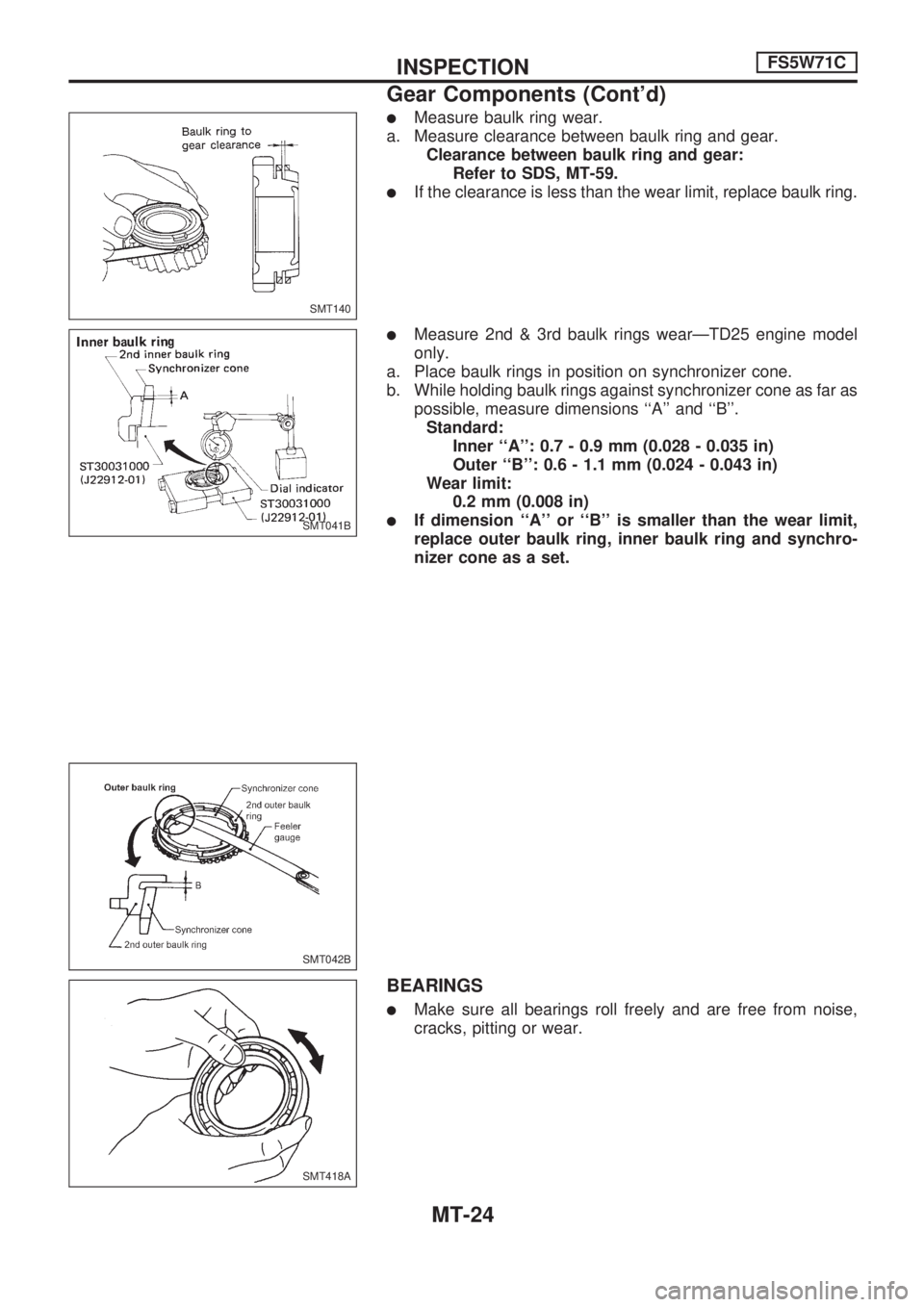
lMeasure baulk ring wear.
a. Measure clearance between baulk ring and gear.
Clearance between baulk ring and gear:
Refer to SDS, MT-59.
lIf the clearance is less than the wear limit, replace baulk ring.
lMeasure 2nd & 3rd baulk rings wearÐTD25 engine model
only.
a. Place baulk rings in position on synchronizer cone.
b. While holding baulk rings against synchronizer cone as far as
possible, measure dimensions ``A'' and ``B''.
Standard:
Inner ``A'': 0.7 - 0.9 mm (0.028 - 0.035 in)
Outer ``B'': 0.6 - 1.1 mm (0.024 - 0.043 in)
Wear limit:
0.2 mm (0.008 in)
lIf dimension ``A'' or ``B'' is smaller than the wear limit,
replace outer baulk ring, inner baulk ring and synchro-
nizer cone as a set.
BEARINGS
lMake sure all bearings roll freely and are free from noise,
cracks, pitting or wear.
SMT140
SMT041B
SMT042B
SMT418A
INSPECTIONFS5W71C
Gear Components (Cont'd)
MT-24
Page 1063 of 1659
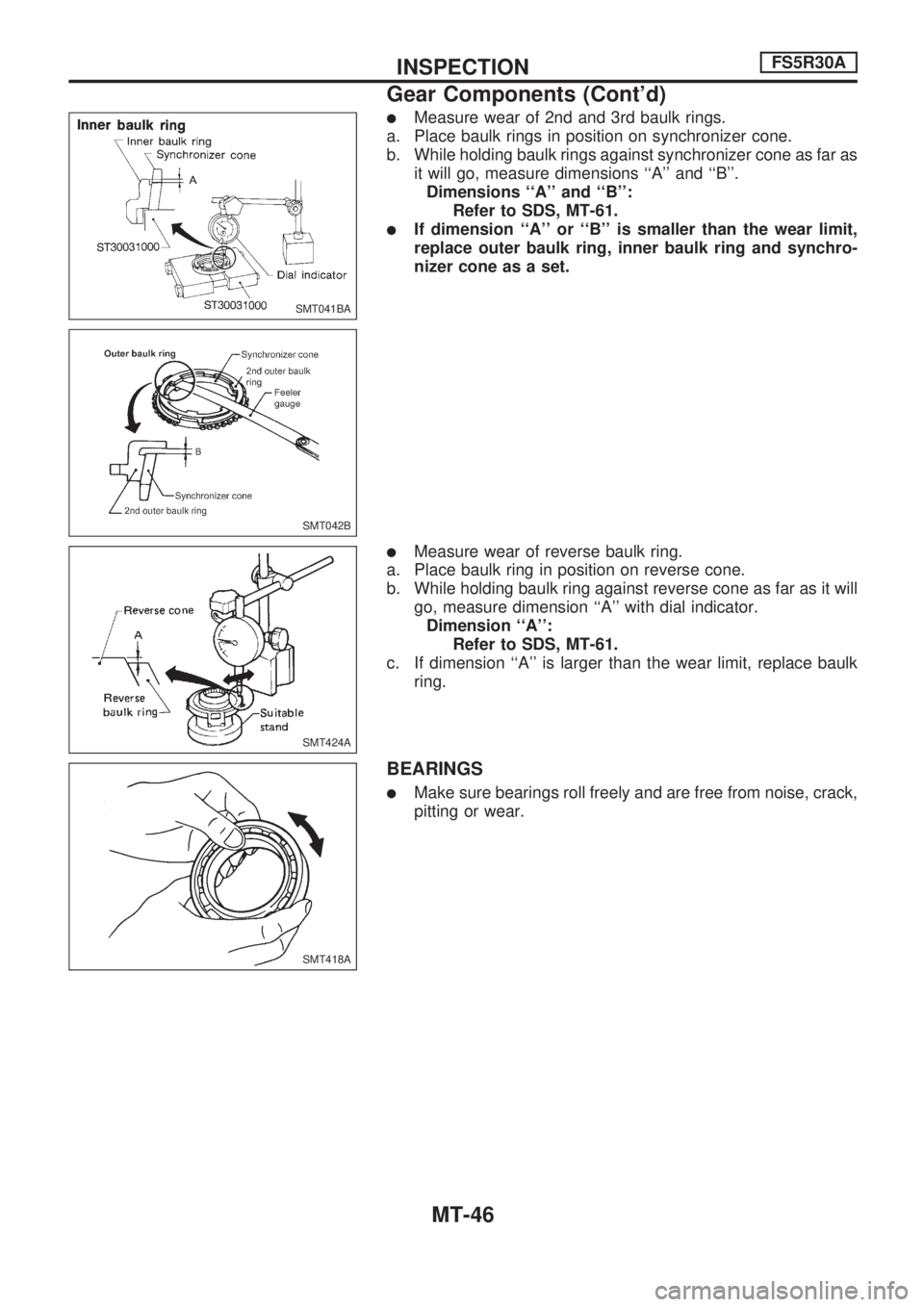
lMeasure wear of 2nd and 3rd baulk rings.
a. Place baulk rings in position on synchronizer cone.
b. While holding baulk rings against synchronizer cone as far as
it will go, measure dimensions ``A'' and ``B''.
Dimensions ``A'' and ``B'':
Refer to SDS, MT-61.
lIf dimension ``A'' or ``B'' is smaller than the wear limit,
replace outer baulk ring, inner baulk ring and synchro-
nizer cone as a set.
lMeasure wear of reverse baulk ring.
a. Place baulk ring in position on reverse cone.
b. While holding baulk ring against reverse cone as far as it will
go, measure dimension ``A'' with dial indicator.
Dimension ``A'':
Refer to SDS, MT-61.
c. If dimension ``A'' is larger than the wear limit, replace baulk
ring.
BEARINGS
lMake sure bearings roll freely and are free from noise, crack,
pitting or wear.
SMT041BA
SMT042B
SMT424A
SMT418A
INSPECTIONFS5R30A
Gear Components (Cont'd)
MT-46
Page 1127 of 1659

5. Install the side bearing caps in their correct locations and
torque the bearing cap retaining bolts.
Specification:
88-98N´m
(9.0 - 10.0 kg-m, 65 - 72 ft-lb)
6. Turn the carrier several times to seat the bearings.
7. Measure the turning torque of the carrier at the ring gear
retaining bolts with a spring gauge.
Specification:
34.3 - 39.2 N
(3.5 - 4.0 kg, 7.7 - 8.8 lb)
of pulling force at the ring gear bolt
8. If the turning torque is not within the specifications, correct
the torque as follows:
lIf the turning torque is less than the specified range, install
washers of greater thickness.
lIf the turning torque is greater than the specification, install
thinner washers.
lSee the SDS section for washer dimensions and part num-
bers.
9. Record the total amount of washer thickness required for the
correct carrier side bearing preload.
10. Remove the carrier from the final drive housing. Save the
selected preload washers for later use during the assembly
of the final drive unit.
SPD526
SPD194A
SPD772
PD344
ADJUSTMENTC200
Side Bearing Preload (Cont'd)
PD-46
Page 1584 of 1659
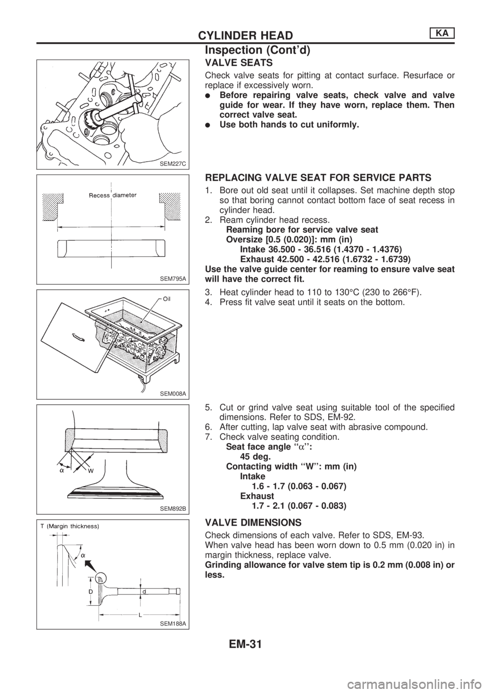
VALVE SEATS
Check valve seats for pitting at contact surface. Resurface or
replace if excessively worn.
lBefore repairing valve seats, check valve and valve
guide for wear. If they have worn, replace them. Then
correct valve seat.
lUse both hands to cut uniformly.
REPLACING VALVE SEAT FOR SERVICE PARTS
1. Bore out old seat until it collapses. Set machine depth stop
so that boring cannot contact bottom face of seat recess in
cylinder head.
2. Ream cylinder head recess.
Reaming bore for service valve seat
Oversize [0.5 (0.020)]: mm (in)
Intake 36.500 - 36.516 (1.4370 - 1.4376)
Exhaust 42.500 - 42.516 (1.6732 - 1.6739)
Use the valve guide center for reaming to ensure valve seat
will have the correct fit.
3. Heat cylinder head to 110 to 130ÉC (230 to 266ÉF).
4. Press fit valve seat until it seats on the bottom.
5. Cut or grind valve seat using suitable tool of the specified
dimensions. Refer to SDS, EM-92.
6. After cutting, lap valve seat with abrasive compound.
7. Check valve seating condition.
Seat face angle ``a'':
45 deg.
Contacting width ``W'': mm (in)
Intake
1.6 - 1.7 (0.063 - 0.067)
Exhaust
1.7 - 2.1 (0.067 - 0.083)
VALVE DIMENSIONS
Check dimensions of each valve. Refer to SDS, EM-93.
When valve head has been worn down to 0.5 mm (0.020 in) in
margin thickness, replace valve.
Grinding allowance for valve stem tip is 0.2 mm (0.008 in) or
less.
SEM227C
SEM795A
SEM008A
SEM892B
SEM188A
CYLINDER HEADKA
Inspection (Cont'd)
EM-31
Page 1611 of 1659

REPLACING VALVE SEAT FOR SERVICE PARTS
1. Bore out old seat until it collapses or remove valve seats with
Tool.
Place a copper seat between contact surface of Tool and
cylinder head.
2. If the valve seat for the exhaust side is oversized, machine
its mating area (on the cylinder head side) to the dimensions
indicated in the table below. Refer to the figure at the left for
machining procedures.
Unit: mm (in)
Oversized valve
seatBore diameter ``d''
TD25
0.2 (0.008)38.695 - 38.710
(1.5234 - 1.5240)
0.4 (0.016)38.895 - 38.910
(1.5313 - 1.5319)
3. Place new valve seats on dry ice and allow them to cool for
five minutes.
WARNING:
Do not touch cooled valve seats with bare hand.
4. Heat cylinder head to 80ÉC (176ÉF).
5. Install cooled valve seats on cylinder head with Tool.
6. Stake exhaust valve seat at five places with punch.
When staking valve seat, select different places than those
staked before.
SEM631B
DEM031
SEM632B
SEM087
CYLINDER HEADTD
Inspection (Cont'd)
EM-58
Page 1612 of 1659

7. Cut or grind valve seat using suitable tool at the specified
dimensions as shown in SDS, EM-100.
8. After cutting, lap valve seat with a lapping compound.
9. Check contact condition of valve seat.
COMBUSTION CHAMBER
Check combustion chamber for cracks and other damage. If
necessary, replace.
REPLACING COMBUSTION CHAMBER
Usually combustion chamber should not be removed.
1. Remove combustion chamber so that cylinder head cannot
be damaged.
2. Install combustion chamber.
Identification of combustion chambers
Identification mark
(on combustion chamber)Outer diameter
``D'' mm (in)Engine
3 places 37 (1.46) TD25
(1) Cool combustion chamber with dry ice for approximately 5 to
10 minutes.
WARNING:
Do not touch cooled combustion chamber with bare hand.
(2) Align combustion chamber knock pin with cylinder head
notch, and drive in combustion chamber with a soft hammer.
3. Check amount of protrusion of combustion chamber.
Protrusion:
Standard
þ0.05 to 0.10 mm (þ0.0020 to 0.0039 in)
VALVE DIMENSIONS
Check dimensions in each valve. For dimensions, refer to SDS.
When valve head has been worn down to 0.5 mm (0.020 in)
in margin thickness, replace the valve.
Grinding allowance for valve stem tip is 0.2 mm (0.008 in) or
less.
SEM633B
DEM107
.
SEM634B
SEM188A
CYLINDER HEADTD
Inspection (Cont'd)
EM-59