differential NISSAN PICK-UP 1998 Repair Manual
[x] Cancel search | Manufacturer: NISSAN, Model Year: 1998, Model line: PICK-UP, Model: NISSAN PICK-UP 1998Pages: 1659, PDF Size: 53.39 MB
Page 1 of 1659
GENERAL INFORMATIONGI
MAINTENANCEMA
ENGINE MECHANICALEM
ENGINE LUBRICATION &
COOLING SYSTEMSLC
ENGINE CONTROL SYSTEMEC
ACCELERATOR CONTROL, FUEL &
EXHAUST SYSTEMSFE
CLUTCHCL
MANUAL TRANSAXLEMT
TRANSFERTF
PROPELLER SHAFT &
DIFFERENTIAL CARRIERPD
FRONT AXLE & FRONT SUSPENSIONFA
REAR AXLE & REAR SUSPENSIONRA
BRAKE SYSTEMBR
STEERING SYSTEMST
RESTRAINT SYSTEMRS
BODY & TRIMBT
HEATER & AIR CONDITIONERHA
ELECTRICAL SYSTEMEL
ALPHABETICAL INDEXIDX
PICKUP
MODEL D22 SERIES
Edition: February 1998
Printing: May 1998 (01)
Publication No.: SM8E-0D22E0E
NISSAN EUROPE S.A.S.
1998 NISSAN EUROPE S.A.S. Printed in the Netherlands
Not to be reproduced in whole or in part without the prior written permission of Nissan Europe S.A.S., Paris, France.
QUICK REFERENCE INDEX
Page 37 of 1659
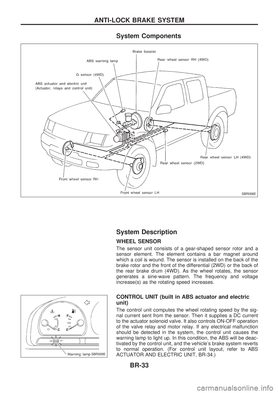
System Components
System Description
WHEEL SENSOR
The sensor unit consists of a gear-shaped sensor rotor and a
sensor element. The element contains a bar magnet around
which a coil is wound. The sensor is installed on the back of the
brake rotor and the front of the differential (2WD) or the back of
the rear brake drum (4WD). As the wheel rotates, the sensor
generates a sine-wave pattern. The frequency and voltage
increase(s) as the rotating speed increases.
CONTROL UNIT (built in ABS actuator and electric
unit)
The control unit computes the wheel rotating speed by the sig-
nal current sent from the sensor. Then it supplies a DC current
to the actuator solenoid valve. It also controls ON-OFF operation
of the valve relay and motor relay. If any electrical malfunction
should be detected in the system, the control unit causes the
warning lamp to light up. In this condition, the ABS will be deac-
tivated by the control unit, and the vehicle's brake system reverts
to normal operation. (For control unit layout, refer to ABS
ACTUATOR AND ELECTRIC UNIT, BR-34.)
SBR068E
SBR069E
ANTI-LOCK BRAKE SYSTEM
BR-33
Page 656 of 1659
Removal
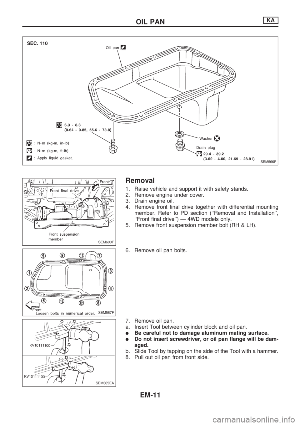
1. Raise vehicle and support it with safety stands.
2. Remove engine under cover.
3. Drain engine oil.
4. Remove front final drive together with differential mounting
member. Refer to PD section (``Removal and Installation'',
``Front final drive'') Ð 4WD models only.
5. Remove front suspension member bolt (RH & LH).
6. Remove oil pan bolts.
7. Remove oil pan.
a. Insert Tool between cylinder block and oil pan.
lBe careful not to damage aluminum mating surface.
lDo not insert screwdriver, or oil pan flange will be dam-
aged.
b. Slide Tool by tapping on the side of the Tool with a hammer.
8. Pull out oil pan from front side.
SEM566F
SEM600F
SEM567F
SEM365EA
OIL PANKA
EM-11
Page 696 of 1659
Measurement of Compression Pressure
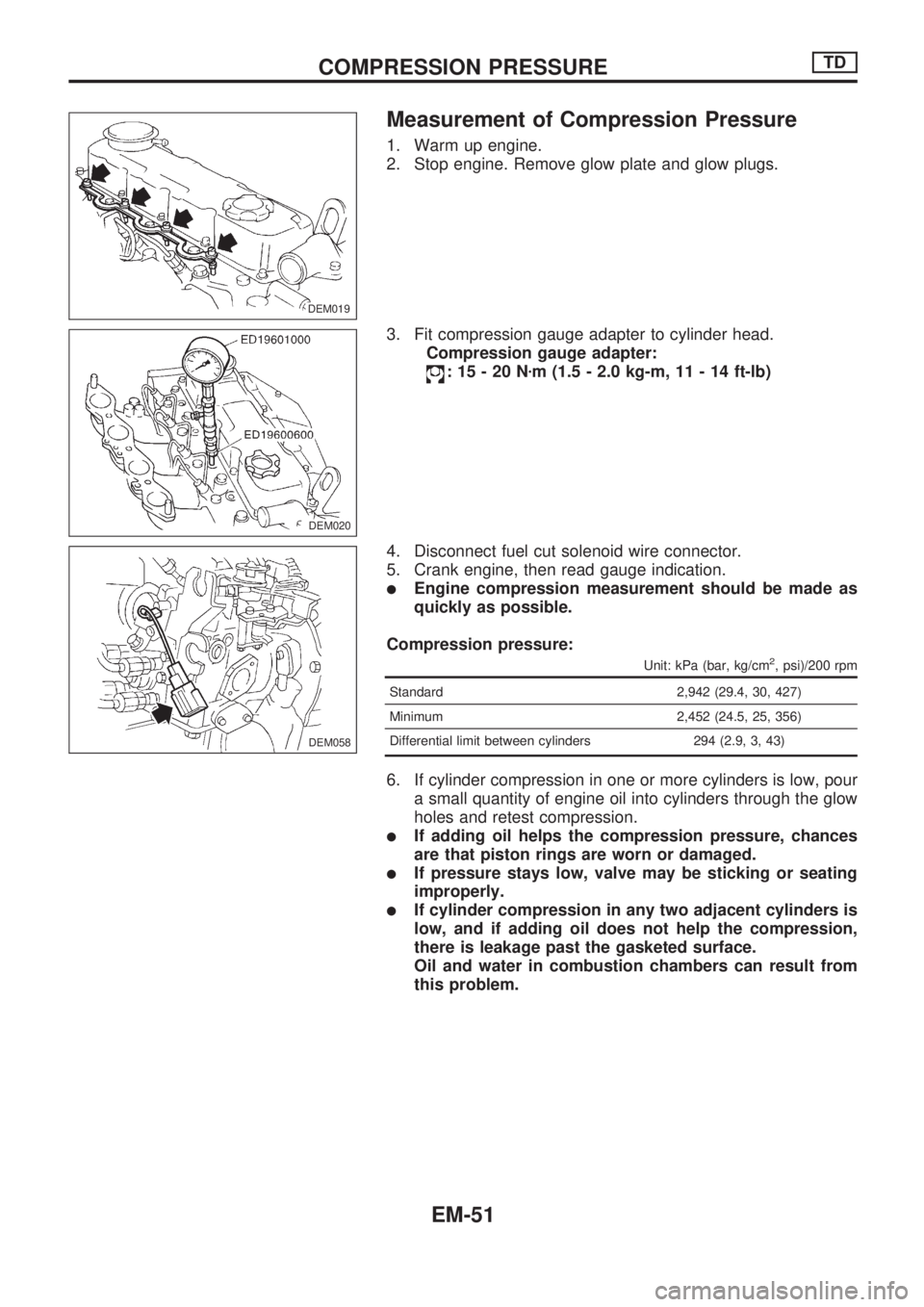
1. Warm up engine.
2. Stop engine. Remove glow plate and glow plugs.
3. Fit compression gauge adapter to cylinder head.
Compression gauge adapter:
:15-20Nzm (1.5 - 2.0 kg-m, 11 - 14 ft-lb)
4. Disconnect fuel cut solenoid wire connector.
5. Crank engine, then read gauge indication.
lEngine compression measurement should be made as
quickly as possible.
Compression pressure:
Unit: kPa (bar, kg/cm2, psi)/200 rpm
Standard 2,942 (29.4, 30, 427)
Minimum 2,452 (24.5, 25, 356)
Differential limit between cylinders 294 (2.9, 3, 43)
6. If cylinder compression in one or more cylinders is low, pour
a small quantity of engine oil into cylinders through the glow
holes and retest compression.
lIf adding oil helps the compression pressure, chances
are that piston rings are worn or damaged.
lIf pressure stays low, valve may be sticking or seating
improperly.
lIf cylinder compression in any two adjacent cylinders is
low, and if adding oil does not help the compression,
there is leakage past the gasketed surface.
Oil and water in combustion chambers can result from
this problem.
DEM019.DEM019
DEM020
DEM058
COMPRESSION PRESSURETD
EM-51
Page 697 of 1659
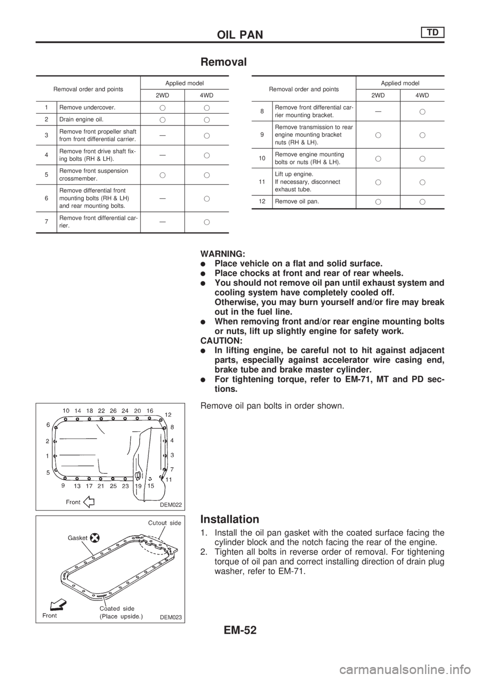
Removal
Removal order and pointsApplied model
2WD 4WD
1 Remove undercover.jj
2 Drain engine oil.jj
3Remove front propeller shaft
from front differential carrier.Ðj
4Remove front drive shaft fix-
ing bolts (RH & LH).Ðj
5Remove front suspension
crossmember.jj
6Remove differential front
mounting bolts (RH & LH)
and rear mounting bolts.Ðj
7Remove front differential car-
rier.ÐjRemoval order and pointsApplied model
2WD 4WD
8Remove front differential car-
rier mounting bracket.Ðj
9Remove transmission to rear
engine mounting bracket
nuts (RH & LH).jj
10Remove engine mounting
bolts or nuts (RH & LH).jj
11Lift up engine.
If necessary, disconnect
exhaust tube.jj
12 Remove oil pan.jj
WARNING:
lPlace vehicle on a flat and solid surface.
lPlace chocks at front and rear of rear wheels.
lYou should not remove oil pan until exhaust system and
cooling system have completely cooled off.
Otherwise, you may burn yourself and/or fire may break
out in the fuel line.
lWhen removing front and/or rear engine mounting bolts
or nuts, lift up slightly engine for safety work.
CAUTION:
lIn lifting engine, be careful not to hit against adjacent
parts, especially against accelerator wire casing end,
brake tube and brake master cylinder.
lFor tightening torque, refer to EM-71, MT and PD sec-
tions.
Remove oil pan bolts in order shown.
Installation
1. Install the oil pan gasket with the coated surface facing the
cylinder block and the notch facing the rear of the engine.
2. Tighten all bolts in reverse order of removal. For tightening
torque of oil pan and correct installing direction of drain plug
washer, refer to EM-71.
DEM022
DEM023
OIL PANTD
EM-52
Page 736 of 1659
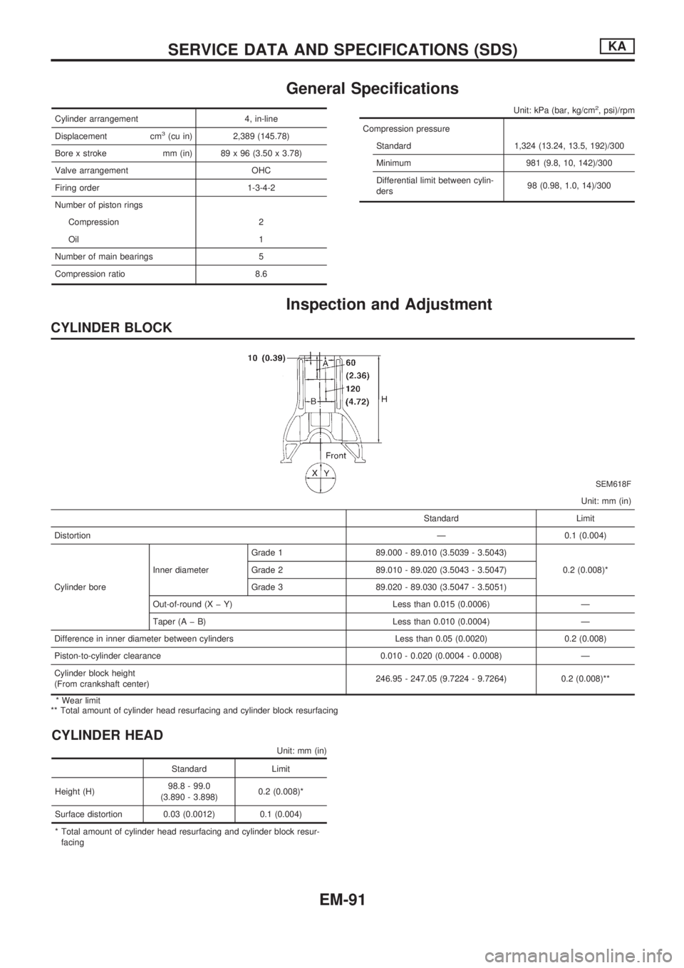
General Specifications
Cylinder arrangement 4, in-line
Displacement cm
3(cu in) 2,389 (145.78)
Bore x stroke mm (in) 89 x 96 (3.50 x 3.78)
Valve arrangement OHC
Firing order 1-3-4-2
Number of piston rings
Compression 2
Oil 1
Number of main bearings 5
Compression ratio 8.6
Unit: kPa (bar, kg/cm2, psi)/rpm
Compression pressure
Standard 1,324 (13.24, 13.5, 192)/300
Minimum 981 (9.8, 10, 142)/300
Differential limit between cylin-
ders98 (0.98, 1.0, 14)/300
Inspection and Adjustment
CYLINDER BLOCK
SEM618F
Unit: mm (in)
Standard Limit
DistortionÐ 0.1 (0.004)
Cylinder boreInner diameterGrade 1 89.000 - 89.010 (3.5039 - 3.5043)
0.2 (0.008)* Grade 2 89.010 - 89.020 (3.5043 - 3.5047)
Grade 3 89.020 - 89.030 (3.5047 - 3.5051)
Out-of-round (X þ Y) Less than 0.015 (0.0006) Ð
Taper (A þ B) Less than 0.010 (0.0004) Ð
Difference in inner diameter between cylinders Less than 0.05 (0.0020) 0.2 (0.008)
Piston-to-cylinder clearance 0.010 - 0.020 (0.0004 - 0.0008) Ð
Cylinder block height
(From crankshaft center)246.95 - 247.05 (9.7224 - 9.7264) 0.2 (0.008)**
* Wear limit
** Total amount of cylinder head resurfacing and cylinder block resurfacing
CYLINDER HEAD
Unit: mm (in)
Standard Limit
Height (H)98.8 - 99.0
(3.890 - 3.898)0.2 (0.008)*
Surface distortion 0.03 (0.0012) 0.1 (0.004)
* Total amount of cylinder head resurfacing and cylinder block resur-
facing
SERVICE DATA AND SPECIFICATIONS (SDS)KA
EM-91
Page 743 of 1659
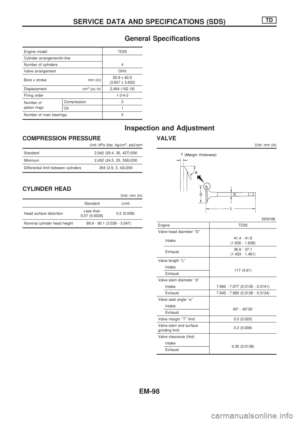
General Specifications
Engine model TD25
Cylinder arrangementIn-line
Number of cylinders 4
Valve arrangement OHV
Bore x stroke mm (in)92.9 x 92.0
(3.657 x 3.622)
Displacement cm
3(cu in) 2,494 (152.18)
Firing order 1-3-4-2
Number of
piston ringsCompression 2
Oil 1
Number of main bearings 5
Inspection and Adjustment
COMPRESSION PRESSURE
Unit: kPa (bar, kg/cm2, psi)/rpm
Standard 2,942 (29.4, 30, 427)/200
Minimum 2,452 (24.5, 25, 356)/200
Differential limit between cylinders 294 (2.9, 3, 43)/200
CYLINDER HEAD
Unit: mm (in)
Standard Limit
Head surface distortionLess than
0.07 (0.0028)0.2 (0.008)
Nominal cylinder head height 89.9 - 90.1 (3.539 - 3.547)
VALVE
Unit: mm (in)
SEM188
Engine TD25
Valve head diameter ``D''
Intake41.4 - 41.6
(1.630 - 1.638)
Exhaust36.9 - 37.1
(1.453 - 1.461)
Valve length ``L''
Intake
117 (4.61)
Exhaust
Valve stem diameter ``d''
Intake 7.962 - 7.977 (0.3135 - 0.3141)
Exhaust 7.945 - 7.960 (0.3128 - 0.3134)
Valve seat angle ``a''
Intake
45É - 45É30¢
Exhaust
Valve margin ``T'' limit 0.5 (0.020)
Valve stem end surface
grinding limit0.2 (0.008)
Valve clearance (Hot)
Intake
0.35 (0.0138)
Exhaust
SERVICE DATA AND SPECIFICATIONS (SDS)TD
EM-98
Page 841 of 1659
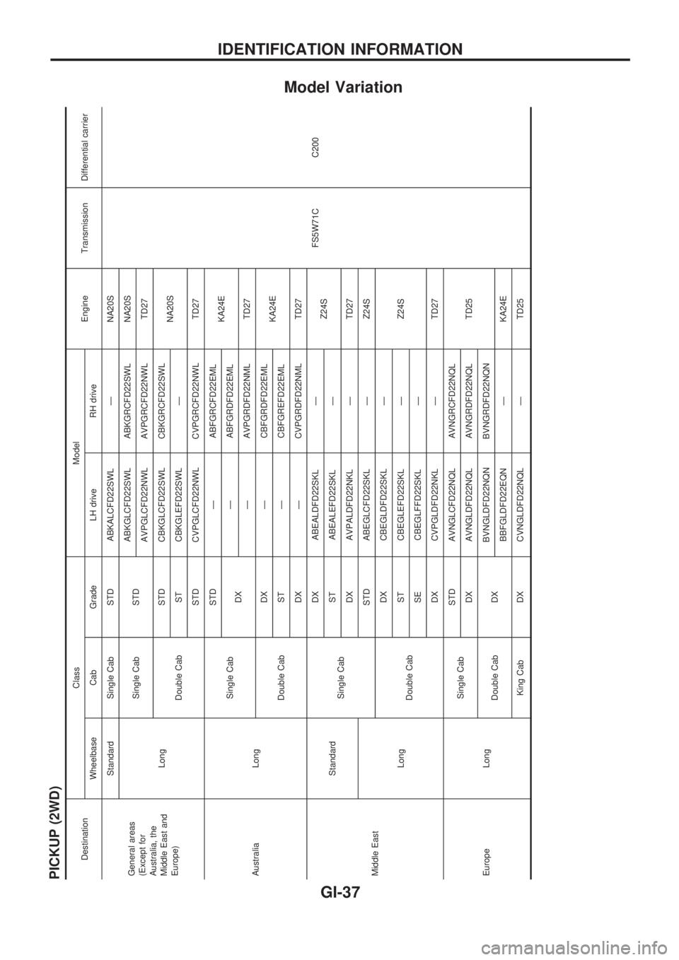
Model Variation
PICKUP (2WD)
DestinationClass Model
Engine Transmission Differential carrier
Wheelbase Cab Grade LH drive RH drive
General areas
(Except for
Australia, the
Middle East and
Europe)Standard Single Cab STD ABKALCFD22SWL Ð NA20S
FS5W71C C200 LongSingle Cab STDABKGLCFD22SWL ABKGRCFD22SWL NA20S
AVPGLCFD22NWL AVPGRCFD22NWL TD27
Double CabSTD CBKGLCFD22SWL CBKGRCFD22SWL
NA20S
ST CBKGLEFD22SWL Ð
STD CVPGLCFD22NWL CVPGRCFD22NWL TD27
Australia LongSingle CabSTD Ð ABFGRCFD22EML
KA24E
DXÐ ABFGRDFD22EML
Ð AVPGRDFD22NML TD27
Double CabDX Ð CBFGRDFD22EML
KA24E
ST Ð CBFGREFD22EML
DX Ð CVPGRDFD22NML TD27
Middle EastStandard
Single CabDX ABEALDFD22SKL Ð
Z24S
ST ABEALEFD22SKL Ð
DX AVPALDFD22NKL Ð TD27
LongSTD ABEGLCFD22SKL Ð Z24S
Double CabDX CBEGLDFD22SKL Ð
Z24S ST CBEGLEFD22SKL Ð
SE CBEGLFFD22SKL Ð
DX CVPGLDFD22NKL Ð TD27
Europe LongSingle CabSTD AVNGLCFD22NQL AVNGRCFD22NQL
TD25 DX AVNGLDFD22NQL AVNGRDFD22NQL
Double Cab DXBVNGLDFD22NQN BVNGRDFD22NQN
BBFGLDFD22EQN Ð KA24E
King Cab DX CVNGLDFD22NQL Ð TD25
IDENTIFICATION INFORMATION
GI-37
Page 842 of 1659
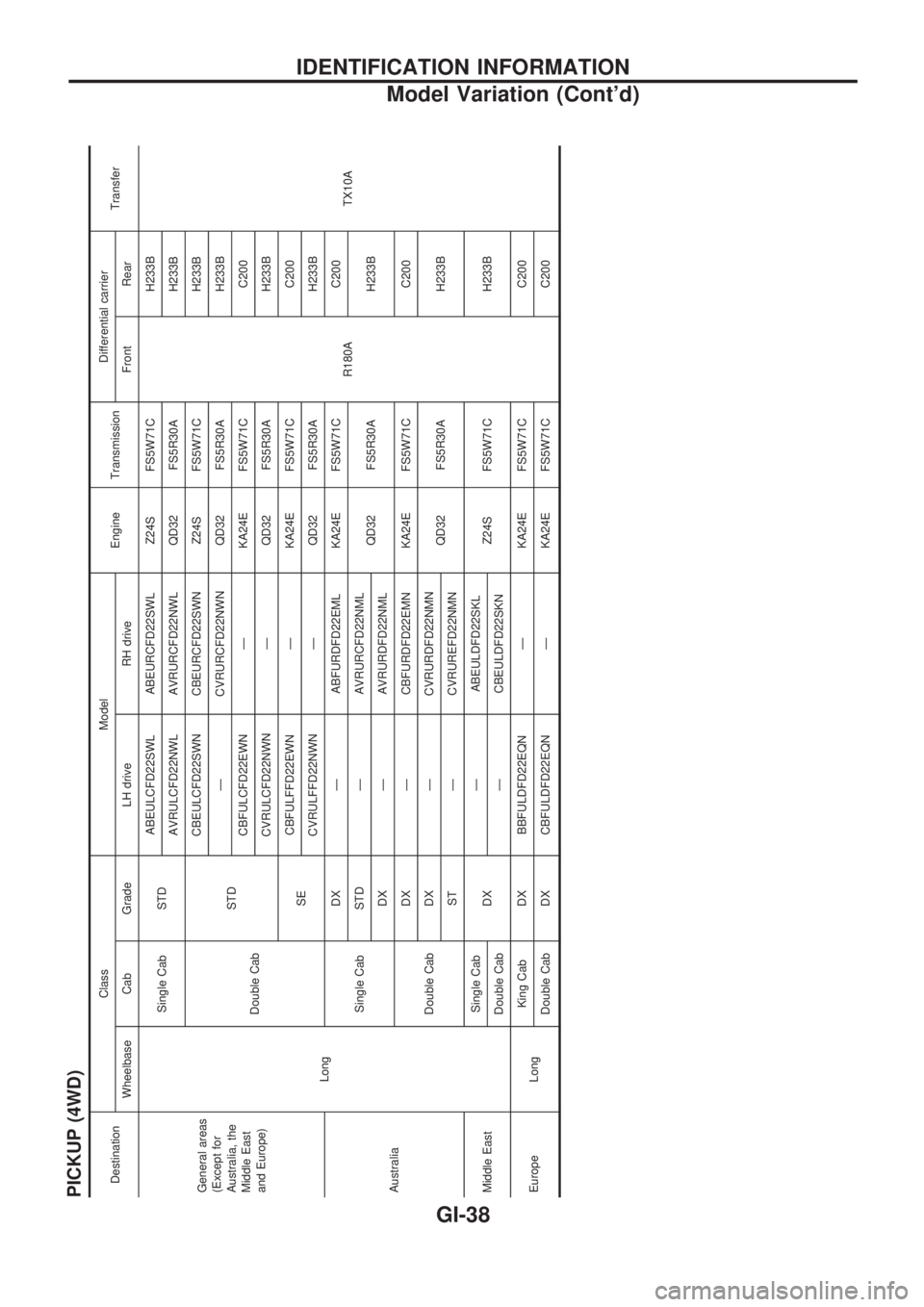
PICKUP (4WD)DestinationClass Model
Engine TransmissionDifferential carrier
Transfer
Wheelbase Cab Grade LH drive RH drive Front Rear
General areas
(Except for
Australia, the
Middle East
and Europe)
LongSingle Cab STDABEULCFD22SWL ABEURCFD22SWL Z24S FS5W71C
R180AH233B
TX10A AVRULCFD22NWL AVRURCFD22NWL QD32 FS5R30A H233B
Double CabSTDCBEULCFD22SWN CBEURCFD22SWN Z24S FS5W71C H233B
Ð CVRURCFD22NWN QD32 FS5R30A H233B
CBFULCFD22EWN Ð KA24E FS5W71C C200
CVRULCFD22NWN Ð QD32 FS5R30A H233B
SECBFULFFD22EWN Ð KA24E FS5W71C C200
CVRULFFD22NWN Ð QD32 FS5R30A H233B
AustraliaSingle CabDX Ð ABFURDFD22EML KA24E FS5W71C C200
STD Ð AVRURCFD22NML
QD32 FS5R30A H233B
DX Ð AVRURDFD22NML
Double CabDX Ð CBFURDFD22EMN KA24E FS5W71C C200
DX Ð CVRURDFD22NMN
QD32 FS5R30A H233B
ST Ð CVRUREFD22NMN
Middle EastSingle Cab
DXÐ ABEULDFD22SKL
Z24S FS5W71C H233B
Double Cab Ð CBEULDFD22SKN
Europe LongKing Cab DX BBFULDFD22EQN Ð KA24E FS5W71C C200
Double Cab DX CBFULDFD22EQN Ð KA24E FS5W71C C200
IDENTIFICATION INFORMATION
Model Variation (Cont'd)
GI-38
Page 860 of 1659
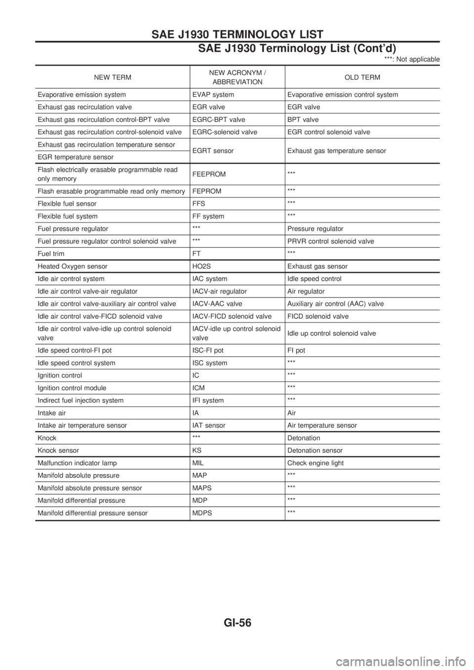
***: Not applicable
NEW TERMNEW ACRONYM /
ABBREVIATIONOLD TERM
Evaporative emission system EVAP system Evaporative emission control system
Exhaust gas recirculation valve EGR valve EGR valve
Exhaust gas recirculation control-BPT valve EGRC-BPT valve BPT valve
Exhaust gas recirculation control-solenoid valve EGRC-solenoid valve EGR control solenoid valve
Exhaust gas recirculation temperature sensor
EGRT sensor Exhaust gas temperature sensor
EGR temperature sensor
Flash electrically erasable programmable read
only memoryFEEPROM ***
Flash erasable programmable read only memory FEPROM ***
Flexible fuel sensor FFS ***
Flexible fuel system FF system ***
Fuel pressure regulator *** Pressure regulator
Fuel pressure regulator control solenoid valve *** PRVR control solenoid valve
Fuel trim FT ***
Heated Oxygen sensor HO2S Exhaust gas sensor
Idle air control system IAC system Idle speed control
Idle air control valve-air regulator IACV-air regulator Air regulator
Idle air control valve-auxiliary air control valve IACV-AAC valve Auxiliary air control (AAC) valve
Idle air control valve-FICD solenoid valve IACV-FICD solenoid valve FICD solenoid valve
Idle air control valve-idle up control solenoid
valveIACV-idle up control solenoid
valveIdle up control solenoid valve
Idle speed control-FI pot ISC-FI pot FI pot
Idle speed control system ISC system ***
Ignition control IC ***
Ignition control module ICM ***
Indirect fuel injection system IFI system ***
Intake air IA Air
Intake air temperature sensor IAT sensor Air temperature sensor
Knock *** Detonation
Knock sensor KS Detonation sensor
Malfunction indicator lamp MIL Check engine light
Manifold absolute pressure MAP ***
Manifold absolute pressure sensor MAPS ***
Manifold differential pressure MDP ***
Manifold differential pressure sensor MDPS ***
SAE J1930 TERMINOLOGY LIST
SAE J1930 Terminology List (Cont'd)
GI-56