combination lamp NISSAN PICK-UP 1998 Owner's Manual
[x] Cancel search | Manufacturer: NISSAN, Model Year: 1998, Model line: PICK-UP, Model: NISSAN PICK-UP 1998Pages: 1659, PDF Size: 53.39 MB
Page 491 of 1659

INSPECTION/VEHICLE SPEED SENSOR
CHECK VEHICLE SPEED SENSOR
OUTPUT.
1. Remove vehicle speed sensor from
transmission.
2. Check voltage between combination
meter terminals
V8andV10while
quickly turning speed sensor pinion.
Voltage: Approx. 0.5V
NG
cOK
Vehicle speed sensor is
OK.
CHECK VEHICLE SPEED SENSOR.
Check resistance between vehicle speed
sensor terminals
V1andV2.
Resistance: Approx. 250W
OK
cNG
Replace vehicle speed
sensor.
Check harness or connector between
speedometer and vehicle speed sensor.
INSPECTION/ENGINE REVOLUTION SIGNAL
(Models with tachometer)
Engine Check itemTerminals
ExplanationÅ@
Injection
DC voltage
V9V26
Higher rpm = Higher voltage
Lower rpm = Lower voltage
Voltage should change with
rpm. Diesel
(TD25)
Carburetor AC voltage
If NG, check the following.
Engine Check item
Injection
lHarness for open or short and connection
Carburetor
lHarness for open or short and connection
lResistor etc.
Diesel
lHarness for open or short and connection
lEngine revolution sensor etc.
SEL167V
SEL118V
SEL168V
.
.
INTERIOR AND SPOT LAMPS
Trouble Diagnoses (Cont'd)
EL-101
Page 492 of 1659

INSPECTION/FUEL TANK GAUGE
CHECK GROUND CIRCUIT FOR FUEL
TANK GAUGE UNIT.
Check harness continuity between fuel
tank gauge unit terminal
V3and ground.
Continuity should exist.
OK
cNG
Repair harness or connec-
tor.
CHECK GAUGE UNITS.
Refer to ``FUEL TANK GAUGE UNIT
CHECK'' (EL-103).
OK
cNG
Repair or replace.
Refer to FE section.
CHECK HARNESS.
1. Disconnect combination meter connec-
tor
N4and fuel tank gauge unit con-
nector.
2. Check harness continuity between
combination meter terminal
V7and
fuel tank gauge unit terminal
V1.
Continuity should exist.
3. Check continuity between combination
meter terminal
V7and ground.
Continuity should not exist.
OK
cNG
Repair harness or connec-
tor.
Fuel tank gauge is OK.
INSPECTION/THERMAL TRANSMITTER
CHECK THERMAL TRANSMITTER.
Refer to ``THERMAL TRANSMITTER
CHECK'' (EL-104).
OK
cNG
Repair or replace.
CHECK HARNESS.
1. Disconnect combination meter connec-
tor
N4and thermal transmitter con-
nector.
2. Check harness for open or short
between combination meter terminal
V6and thermal transmitter terminal
V1.
3. Check continuity between combination
meter terminal
V6and ground.
Continuity should not exist.
OK
cNG
Repair harness or connec-
tor.
Thermal transmitter is OK.
SEL169V
SEL170V
SEL171V
.
.
.
.
.
INTERIOR AND SPOT LAMPS
Trouble Diagnoses (Cont'd)
EL-102
Page 506 of 1659
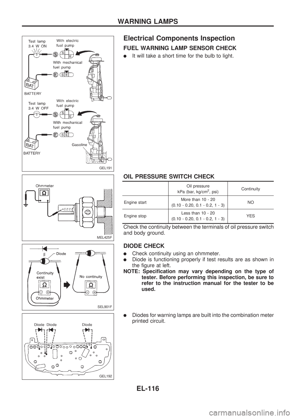
Electrical Components Inspection
FUEL WARNING LAMP SENSOR CHECK
lIt will take a short time for the bulb to light.
OIL PRESSURE SWITCH CHECK
Oil pressure
kPa (bar, kg/cm2, psi)Continuity
Engine startMore than 10 - 20
(0.10 - 0.20, 0.1 - 0.2,1-3)NO
Engine stopLess than 10 - 20
(0.10 - 0.20, 0.1 - 0.2,1-3)YES
Check the continuity between the terminals of oil pressure switch
and body ground.
DIODE CHECK
lCheck continuity using an ohmmeter.
lDiode is functioning properly if test results are as shown in
the figure at left.
NOTE: Specification may vary depending on the type of
tester. Before performing this inspection, be sure to
refer to the instruction manual for the tester to be
used.
lDiodes for warning lamps are built into the combination meter
printed circuit.
GEL191
MEL425F
SEL901F
GEL192
WARNING LAMPS
EL-116
Page 642 of 1659
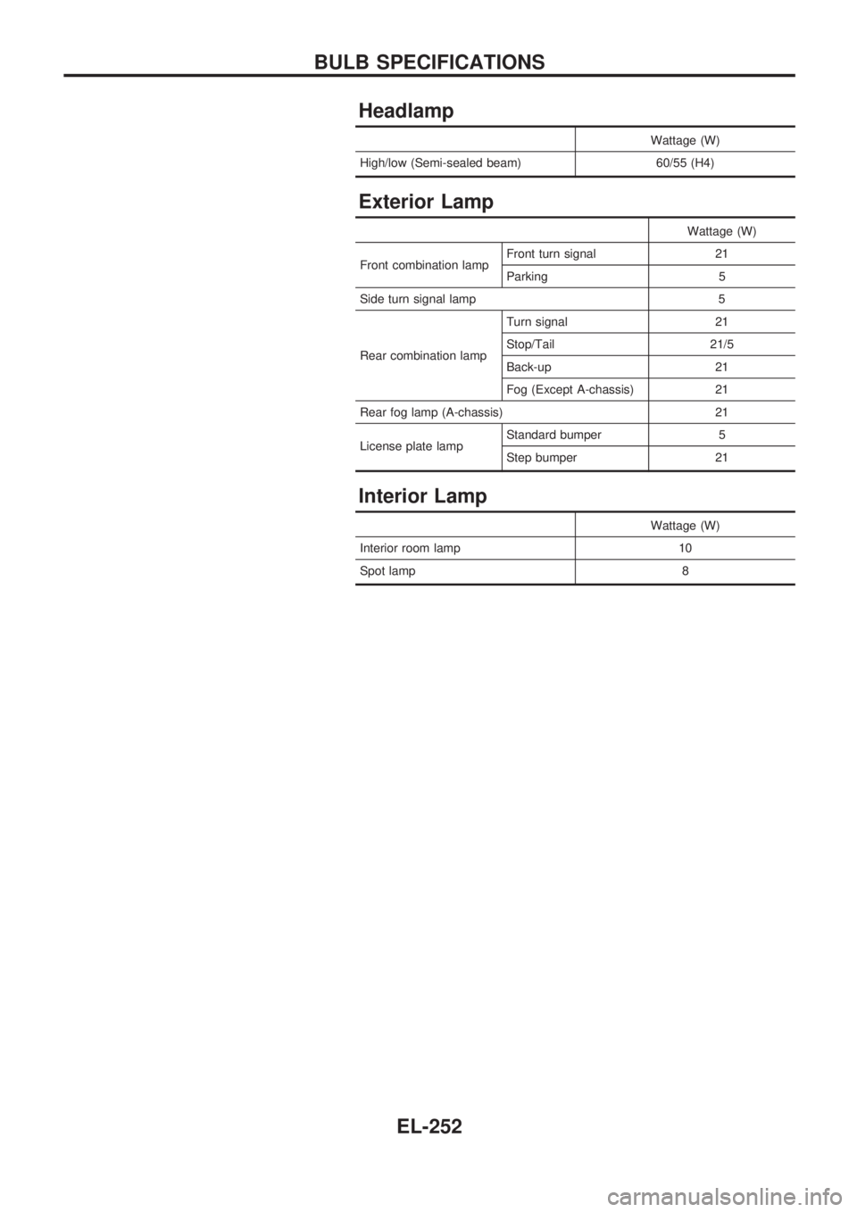
Headlamp
Wattage (W)
High/low (Semi-sealed beam) 60/55 (H4)
Exterior Lamp
Wattage (W)
Front combination lampFront turn signal 21
Parking 5
Side turn signal lamp 5
Rear combination lampTurn signal 21
Stop/Tail 21/5
Back-up 21
Fog (Except A-chassis) 21
Rear fog lamp (A-chassis) 21
License plate lampStandard bumper 5
Step bumper 21
Interior Lamp
Wattage (W)
Interior room lamp 10
Spot lamp 8
BULB SPECIFICATIONS
EL-252
Page 865 of 1659
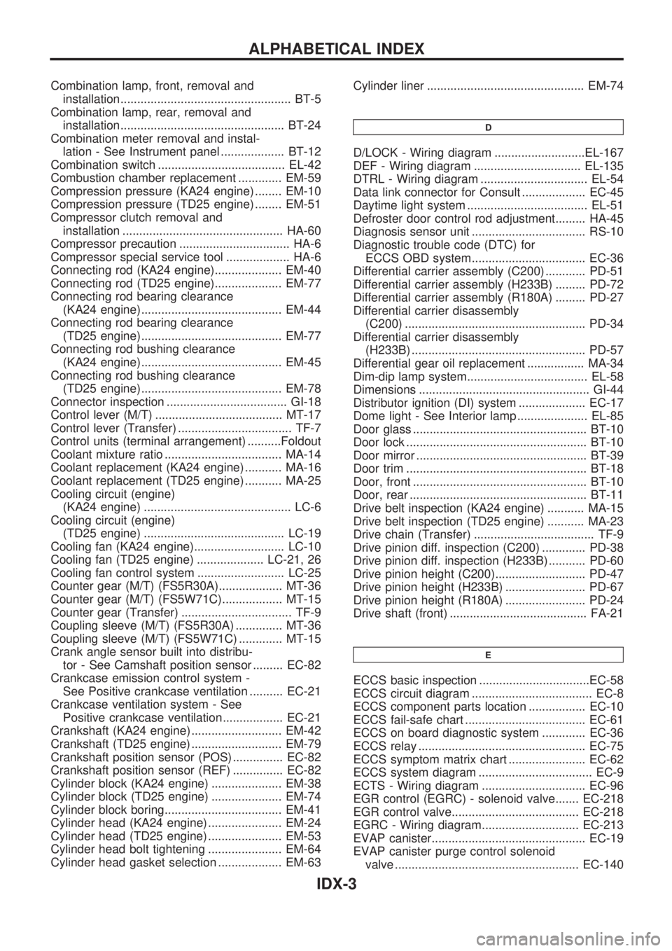
Combination lamp, front, removal and
installation................................................... BT-5
Combination lamp, rear, removal and
installation................................................. BT-24
Combination meter removal and instal-
lation - See Instrument panel ................... BT-12
Combination switch ...................................... EL-42
Combustion chamber replacement ............. EM-59
Compression pressure (KA24 engine) ........ EM-10
Compression pressure (TD25 engine) ........ EM-51
Compressor clutch removal and
installation ................................................ HA-60
Compressor precaution ................................. HA-6
Compressor special service tool ................... HA-6
Connecting rod (KA24 engine).................... EM-40
Connecting rod (TD25 engine).................... EM-77
Connecting rod bearing clearance
(KA24 engine).......................................... EM-44
Connecting rod bearing clearance
(TD25 engine).......................................... EM-77
Connecting rod bushing clearance
(KA24 engine).......................................... EM-45
Connecting rod bushing clearance
(TD25 engine).......................................... EM-78
Connector inspection .................................... GI-18
Control lever (M/T) ...................................... MT-17
Control lever (Transfer) .................................. TF-7
Control units (terminal arrangement) ..........Foldout
Coolant mixture ratio ................................... MA-14
Coolant replacement (KA24 engine) ........... MA-16
Coolant replacement (TD25 engine) ........... MA-25
Cooling circuit (engine)
(KA24 engine) ............................................ LC-6
Cooling circuit (engine)
(TD25 engine) .......................................... LC-19
Cooling fan (KA24 engine)........................... LC-10
Cooling fan (TD25 engine) .................... LC-21, 26
Cooling fan control system .......................... LC-25
Counter gear (M/T) (FS5R30A)................... MT-36
Counter gear (M/T) (FS5W71C).................. MT-15
Counter gear (Transfer) ................................. TF-9
Coupling sleeve (M/T) (FS5R30A) .............. MT-36
Coupling sleeve (M/T) (FS5W71C) ............. MT-15
Crank angle sensor built into distribu-
tor - See Camshaft position sensor ......... EC-82
Crankcase emission control system -
See Positive crankcase ventilation .......... EC-21
Crankcase ventilation system - See
Positive crankcase ventilation.................. EC-21
Crankshaft (KA24 engine) ........................... EM-42
Crankshaft (TD25 engine) ........................... EM-79
Crankshaft position sensor (POS) ............... EC-82
Crankshaft position sensor (REF) ............... EC-82
Cylinder block (KA24 engine) ..................... EM-38
Cylinder block (TD25 engine) ..................... EM-74
Cylinder block boring................................... EM-41
Cylinder head (KA24 engine) ...................... EM-24
Cylinder head (TD25 engine) ...................... EM-53
Cylinder head bolt tightening ...................... EM-64
Cylinder head gasket selection ................... EM-63Cylinder liner ............................................... EM-74
D
D/LOCK - Wiring diagram ...........................EL-167
DEF - Wiring diagram ................................ EL-135
DTRL - Wiring diagram ................................ EL-54
Data link connector for Consult ................... EC-45
Daytime light system .................................... EL-51
Defroster door control rod adjustment......... HA-45
Diagnosis sensor unit .................................. RS-10
Diagnostic trouble code (DTC) for
ECCS OBD system.................................. EC-36
Differential carrier assembly (C200) ............ PD-51
Differential carrier assembly (H233B) ......... PD-72
Differential carrier assembly (R180A) ......... PD-27
Differential carrier disassembly
(C200) ...................................................... PD-34
Differential carrier disassembly
(H233B) .................................................... PD-57
Differential gear oil replacement ................. MA-34
Dim-dip lamp system.................................... EL-58
Dimensions ................................................... GI-44
Distributor ignition (DI) system .................... EC-17
Dome light - See Interior lamp ..................... EL-85
Door glass .................................................... BT-10
Door lock ...................................................... BT-10
Door mirror ................................................... BT-39
Door trim ...................................................... BT-18
Door, front .................................................... BT-10
Door, rear ..................................................... BT-11
Drive belt inspection (KA24 engine) ........... MA-15
Drive belt inspection (TD25 engine) ........... MA-23
Drive chain (Transfer) .................................... TF-9
Drive pinion diff. inspection (C200) ............. PD-38
Drive pinion diff. inspection (H233B) ........... PD-60
Drive pinion height (C200)........................... PD-47
Drive pinion height (H233B) ........................ PD-67
Drive pinion height (R180A) ........................ PD-24
Drive shaft (front) ......................................... FA-21
E
ECCS basic inspection .................................EC-58
ECCS circuit diagram .................................... EC-8
ECCS component parts location ................. EC-10
ECCS fail-safe chart .................................... EC-61
ECCS on board diagnostic system ............. EC-36
ECCS relay .................................................. EC-75
ECCS symptom matrix chart ....................... EC-62
ECCS system diagram .................................. EC-9
ECTS - Wiring diagram ............................... EC-96
EGR control (EGRC) - solenoid valve....... EC-218
EGR control valve...................................... EC-218
EGRC - Wiring diagram............................. EC-213
EVAP canister.............................................. EC-19
EVAP canister purge control solenoid
valve ....................................................... EC-140
ALPHABETICAL INDEX
IDX-3
Page 866 of 1659
EVAP vapor lines inspection ....................... MA-22
Electrical diagnoses ...................................... GI-21
Engine compartment .................................... BT-44
Engine control module (ECM) ....................... EC-5
Engine coolant temperature sensor
(ECTS) (KA24 engine) ............................. EC-95
Engine coolant temperature sensor
(ECTS) (TD25 engine) ........................... EC-209
Engine oil filter replacement
(KA24 engine).......................................... MA-20
Engine oil filter replacement
(TD25 engine).......................................... MA-24
Engine oil precautions .................................... GI-4
Engine oil replacement
(KA24 engine).......................................... MA-19
Engine oil replacement
(TD25 engine).......................................... MA-24
Engine outer component parts
(KA24 engine)............................................ EM-9
Engine outer component parts
(TD25 engine).......................................... EM-49
Engine removal (KA24 engine) ................... EM-36
Engine removal (TD25 engine) ................... EM-69
Engine room - See Engine
compartment............................................. BT-44
Engine speed sensor ................................. EC-219
Evaporative emission (EVAP) system ......... EC-19
Exhaust system inspection.......................... MA-32
Exhaust system .............................................. FE-5
Exterior ......................................................... BT-24
F
F/PUMP - Wiring diagram...........................EC-153
FCUT - Wiring diagram ............................. EC-225
FICD - Wiring diagram (KA24 engine) ...... EC-168
FICD - Wiring diagram (TD25 engine) ...... EC-230
Fan switch.................................................... HA-43
Fast idle cam (FIC) inspection and
adjustment................................................ EC-24
Final drive disassembly (C200) ................... PD-34
Final drive disassembly (H233B)................. PD-56
Final drive pre-inspection (C200) ................ PD-34
Final drive pre-inspection (H233B) .............. PD-56
Final drive removal and installation ............. PD-15
Floor trim ...................................................... BT-15
Flow charts.................................................... GI-31
Fluids ........................................................... MA-12
Flywheel (clutch) .......................................... CL-12
Flywheel runout (KA24 engine)................... EM-45
Flywheel runout (TD25 engine)................... EM-80
Fog lamp, rear .............................................. EL-72
Fork rod (M/T) (FS5R30A) .......................... MT-38
Fork rod (M/T) (FS5W71C) ......................... MT-17
Front axle ..................................................... FA-12
Front bumper.................................................. BT-5
Front case (Transfer) ..................................... TF-8
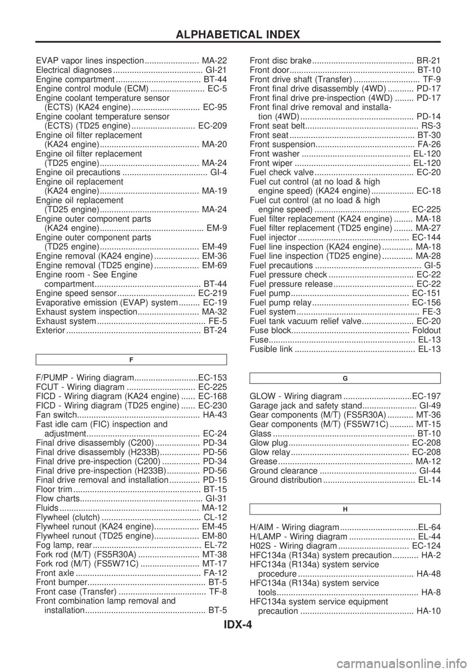
Front combination lamp removal and
installation................................................... BT-5Front disc brake ........................................... BR-21
Front door..................................................... BT-10
Front drive shaft (Transfer) ............................ TF-9
Front final drive disassembly (4WD) ........... PD-17
Front final drive pre-inspection (4WD) ........ PD-17
Front final drive removal and installa-
tion (4WD) ................................................ PD-14
Front seat belt................................................ RS-3
Front seat ..................................................... BT-30
Front suspension.......................................... FA-26
Front washer .............................................. EL-120
Front wiper ................................................. EL-120
Fuel check valve .......................................... EC-20
Fuel cut control (at no load & high
engine speed) (KA24 engine) .................. EC-18
Fuel cut control (at no load & high
engine speed) ........................................ EC-225
Fuel filter replacement (KA24 engine) ........ MA-18
Fuel filter replacement (TD25 engine) ........ MA-27
Fuel injector ............................................... EC-144
Fuel line inspection (KA24 engine) ............. MA-18
Fuel line inspection (TD25 engine) ............. MA-28
Fuel precautions ............................................. GI-5
Fuel pressure check .................................... EC-22
Fuel pressure release .................................. EC-22
Fuel pump .................................................. EC-151
Fuel pump relay ......................................... EC-156
Fuel system .................................................... FE-3
Fuel tank vacuum relief valve...................... EC-20
Fuse block.................................................. Foldout
Fuse.............................................................. EL-13
Fusible link ................................................... EL-13G
GLOW - Wiring diagram .............................EC-197
Garage jack and safety stand....................... GI-49
Gear components (M/T) (FS5R30A) ........... MT-36
Gear components (M/T) (FS5W71C) .......... MT-15
Glass ............................................................ BT-10
Glow plug ................................................... EC-208
Glow relay .................................................. EC-208
Grease ......................................................... MA-12
Ground clearance ......................................... GI-44
Ground distribution ....................................... EL-14
H
H/AIM - Wiring diagram .................................EL-64
H/LAMP - Wiring diagram ............................ EL-44
H02S - Wiring diagram .............................. EC-124
HFC134a (R134a) system precaution ........... HA-2
HFC134a (R134a) system service
procedure ................................................. HA-48
HFC134a (R134a) system service
tools............................................................ HA-8
HFC134a system service equipment
precaution ................................................ HA-10
ALPHABETICAL INDEX
IDX-4
Page 869 of 1659
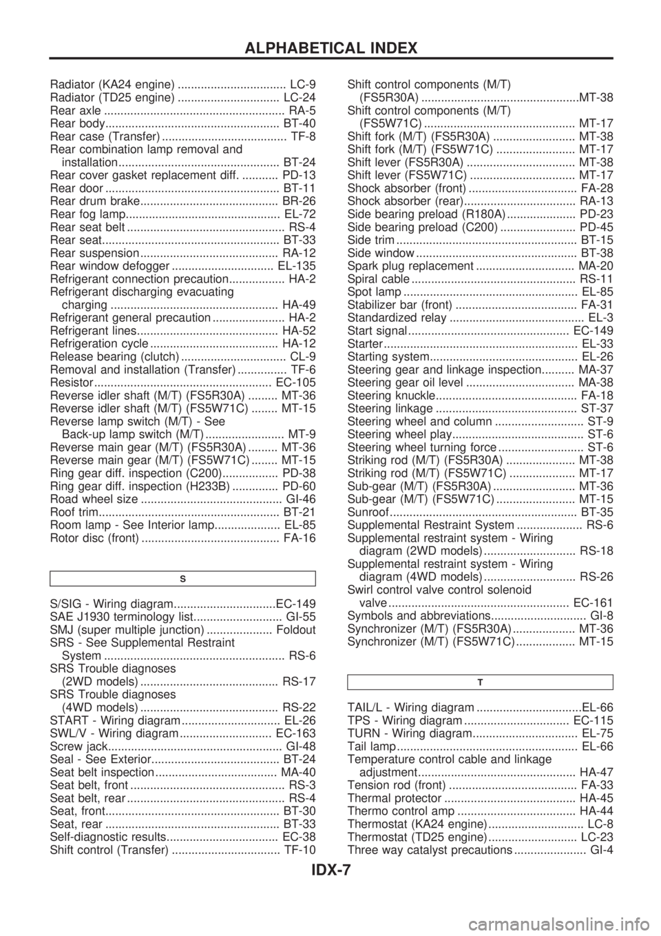
Radiator (KA24 engine) ................................. LC-9
Radiator (TD25 engine) ............................... LC-24
Rear axle ....................................................... RA-5
Rear body..................................................... BT-40
Rear case (Transfer) ...................................... TF-8
Rear combination lamp removal and
installation................................................. BT-24
Rear cover gasket replacement diff. ........... PD-13
Rear door ..................................................... BT-11
Rear drum brake.......................................... BR-26
Rear fog lamp............................................... EL-72
Rear seat belt ................................................ RS-4
Rear seat...................................................... BT-33
Rear suspension .......................................... RA-12
Rear window defogger ............................... EL-135
Refrigerant connection precaution................. HA-2
Refrigerant discharging evacuating
charging ................................................... HA-49
Refrigerant general precaution ...................... HA-2
Refrigerant lines........................................... HA-52
Refrigeration cycle ....................................... HA-12
Release bearing (clutch) ................................ CL-9
Removal and installation (Transfer) ............... TF-6
Resistor ...................................................... EC-105
Reverse idler shaft (M/T) (FS5R30A) ......... MT-36
Reverse idler shaft (M/T) (FS5W71C) ........ MT-15
Reverse lamp switch (M/T) - See
Back-up lamp switch (M/T) ........................ MT-9
Reverse main gear (M/T) (FS5R30A) ......... MT-36
Reverse main gear (M/T) (FS5W71C) ........ MT-15
Ring gear diff. inspection (C200)................. PD-38
Ring gear diff. inspection (H233B) .............. PD-60
Road wheel size ........................................... GI-46
Roof trim....................................................... BT-21
Room lamp - See Interior lamp.................... EL-85
Rotor disc (front) .......................................... FA-16
S
S/SIG - Wiring diagram...............................EC-149
SAE J1930 terminology list........................... GI-55
SMJ (super multiple junction) .................... Foldout
SRS - See Supplemental Restraint
System ....................................................... RS-6
SRS Trouble diagnoses
(2WD models) .......................................... RS-17
SRS Trouble diagnoses
(4WD models) .......................................... RS-22
START - Wiring diagram .............................. EL-26
SWL/V - Wiring diagram ............................ EC-163
Screw jack..................................................... GI-48
Seal - See Exterior....................................... BT-24
Seat belt inspection ..................................... MA-40
Seat belt, front ............................................... RS-3
Seat belt, rear ................................................ RS-4
Seat, front..................................................... BT-30
Seat, rear ..................................................... BT-33
Self-diagnostic results.................................. EC-38
Shift control (Transfer) ................................. TF-10Shift control components (M/T)
(FS5R30A) ................................................MT-38
Shift control components (M/T)
(FS5W71C) .............................................. MT-17
Shift fork (M/T) (FS5R30A) ......................... MT-38
Shift fork (M/T) (FS5W71C) ........................ MT-17
Shift lever (FS5R30A) ................................. MT-38
Shift lever (FS5W71C) ................................ MT-17
Shock absorber (front) ................................. FA-28
Shock absorber (rear).................................. RA-13
Side bearing preload (R180A) ..................... PD-23
Side bearing preload (C200) ....................... PD-45
Side trim ....................................................... BT-15
Side window ................................................. BT-38
Spark plug replacement .............................. MA-20
Spiral cable .................................................. RS-11
Spot lamp ..................................................... EL-85
Stabilizer bar (front) ..................................... FA-31
Standardized relay ......................................... EL-3
Start signal ................................................. EC-149
Starter ........................................................... EL-33
Starting system............................................. EL-26
Steering gear and linkage inspection.......... MA-37
Steering gear oil level ................................. MA-38
Steering knuckle........................................... FA-18
Steering linkage ........................................... ST-37
Steering wheel and column ........................... ST-9
Steering wheel play........................................ ST-6
Steering wheel turning force .......................... ST-6
Striking rod (M/T) (FS5R30A) ..................... MT-38
Striking rod (M/T) (FS5W71C) .................... MT-17
Sub-gear (M/T) (FS5R30A) ......................... MT-36
Sub-gear (M/T) (FS5W71C) ........................ MT-15
Sunroof ......................................................... BT-35
Supplemental Restraint System .................... RS-6
Supplemental restraint system - Wiring
diagram (2WD models) ............................ RS-18
Supplemental restraint system - Wiring
diagram (4WD models) ............................ RS-26
Swirl control valve control solenoid
valve ....................................................... EC-161
Symbols and abbreviations............................. GI-8
Synchronizer (M/T) (FS5R30A) ................... MT-36
Synchronizer (M/T) (FS5W71C) .................. MT-15
T
TAIL/L - Wiring diagram ................................EL-66
TPS - Wiring diagram ................................ EC-115
TURN - Wiring diagram................................ EL-75
Tail lamp ....................................................... EL-66
Temperature control cable and linkage
adjustment................................................ HA-47
Tension rod (front) ....................................... FA-33
Thermal protector ........................................ HA-45
Thermo control amp .................................... HA-44
Thermostat (KA24 engine) ............................. LC-8
Thermostat (TD25 engine) ........................... LC-23
Three way catalyst precautions ...................... GI-4
ALPHABETICAL INDEX
IDX-7
Page 1183 of 1659

REPAIR PROCEDURES
CAUTION:
Before servicing air bag, turn the ignition switch off and disconnect both battery cables and wait at
least 3 minutes.
Warning lamp operation Explanation Repair order
Warning lamp blinks.*Open or short in the air bag module cir-
cuit.1. Visually check the wiring harness and connectors.
2. Replace air bag module.
3. Replace steering wheel assembly (including diagnosis
sensor unit). Malfunctioning diagnosis sensor unit
Warning lamp does not illu-
minate at all.Meter fuse is blown.
1. Check meter fuse.
2. Visually check the wiring harnesses and connectors.
3. Check warning lamp LED.
4. Replace spiral cable.
5. Replace steering wheel assembly (including diagnosis
sensor unit).
6. Replace combination meter. Open in the warning lamp power supply
circuit
Short circuit between the warning lamp
and diagnoses sensor unit.
Malfunctioning LED
Malfunctioning combination meter
Malfunctioning diagnosis sensor unit
Warning lamp is continu-
ously ON.SRS air bag fuse is blown.1. Check air bag fuse.
2. Visually check the wiring harnesses and connectors for
combination meter, diagnosis sensor unit and spiral
cable.
3. Replace spiral cable.
4. Replace steering wheel assembly (including diagnosis
sensor unit). Open in circuit between the warning
lamp and diagnoses sensor unit.
Malfunctioning diagnosis sensor unit
*: After air bag is deployed, the warning lamp might blink due to an open circuit in the air bag module.
Follow the procedures in numerical order when repairing malfunctioning parts. Confirm whether malfunction is eliminated
using the air bag warning lamp each time repair is finished. If malfunction is still observed, proceed to the next step. When
malfunction is eliminated, further repair work is not required.
TROUBLE DIAGNOSES Ð Supplemental Restraint System (SRS) Ð
2WD models
Self-diagnosis (Cont'd)
RS-20
Page 1205 of 1659
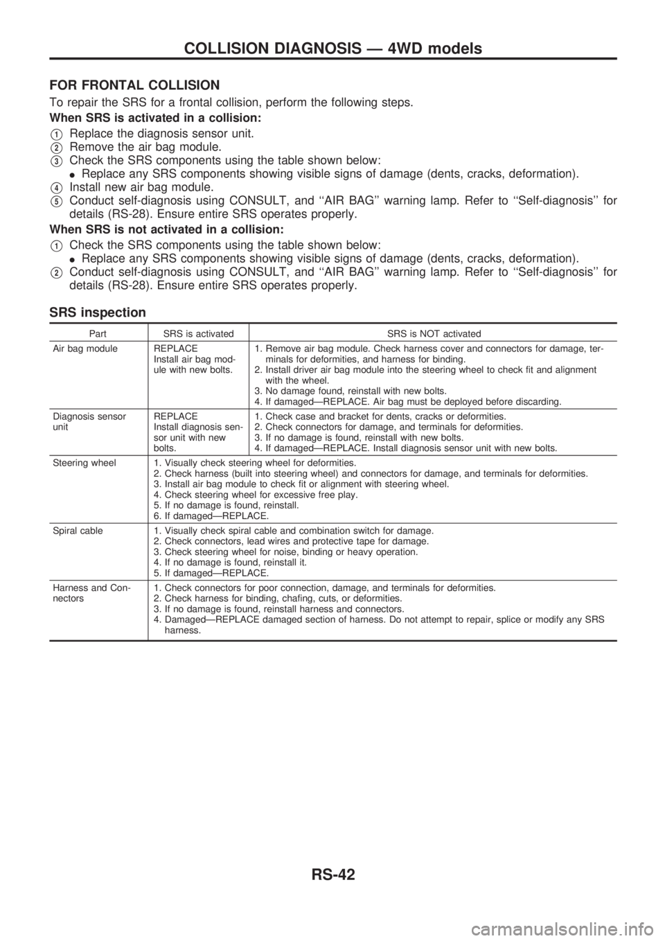
FOR FRONTAL COLLISION
To repair the SRS for a frontal collision, perform the following steps.
When SRS is activated in a collision:
V1Replace the diagnosis sensor unit.
V2Remove the air bag module.
V3Check the SRS components using the table shown below:
lReplace any SRS components showing visible signs of damage (dents, cracks, deformation).
V4Install new air bag module.
V5Conduct self-diagnosis using CONSULT, and ``AIR BAG'' warning lamp. Refer to ``Self-diagnosis'' for
details (RS-28). Ensure entire SRS operates properly.
When SRS is not activated in a collision:
V1Check the SRS components using the table shown below:
lReplace any SRS components showing visible signs of damage (dents, cracks, deformation).
V2Conduct self-diagnosis using CONSULT, and ``AIR BAG'' warning lamp. Refer to ``Self-diagnosis'' for
details (RS-28). Ensure entire SRS operates properly.
SRS inspection
Part SRS is activated SRS is NOT activated
Air bag module REPLACE
Install air bag mod-
ule with new bolts.1. Remove air bag module. Check harness cover and connectors for damage, ter-
minals for deformities, and harness for binding.
2. Install driver air bag module into the steering wheel to check fit and alignment
with the wheel.
3. No damage found, reinstall with new bolts.
4. If damagedÐREPLACE. Air bag must be deployed before discarding.
Diagnosis sensor
unitREPLACE
Install diagnosis sen-
sor unit with new
bolts.1. Check case and bracket for dents, cracks or deformities.
2. Check connectors for damage, and terminals for deformities.
3. If no damage is found, reinstall with new bolts.
4. If damagedÐREPLACE. Install diagnosis sensor unit with new bolts.
Steering wheel 1. Visually check steering wheel for deformities.
2. Check harness (built into steering wheel) and connectors for damage, and terminals for deformities.
3. Install air bag module to check fit or alignment with steering wheel.
4. Check steering wheel for excessive free play.
5. If no damage is found, reinstall.
6. If damagedÐREPLACE.
Spiral cable 1. Visually check spiral cable and combination switch for damage.
2. Check connectors, lead wires and protective tape for damage.
3. Check steering wheel for noise, binding or heavy operation.
4. If no damage is found, reinstall it.
5. If damagedÐREPLACE.
Harness and Con-
nectors1. Check connectors for poor connection, damage, and terminals for deformities.
2. Check harness for binding, chafing, cuts, or deformities.
3. If no damage is found, reinstall harness and connectors.
4. DamagedÐREPLACE damaged section of harness. Do not attempt to repair, splice or modify any SRS
harness.
COLLISION DIAGNOSIS Ð 4WD models
RS-42
Page 1232 of 1659

3. Remove steering wheel using Tool.
lFor installation, refer to RS section [``Air Bag Module and
Spiral Cable'', ``SUPPLEMENTAL RESTRAINT SYSTEM
(SRS)''].
Steering Column
REMOVAL
CAUTION:
lThe rotation of the spiral cable (SRS ``Air bag'' compo-
nent part) is limited. If the steering gear must be
removed, set the front wheels in the straight-ahead
direction.
Do not rotate the steering column while the steering gear
is removed.
lRemove the steering wheel before removing the steering
lower joint to avoid damaging the SRS spiral cable. Refer
to ST-9.
1. Remove steering wheel, refer to ST-9.
2. Remove steering column cover.
3. Remove instrument lower panel.
4. Disconnect combination switch electrical connectors and air
bag harness connector.
5. Remove dash insulator.
6. Remove bolt from lower joint.
7. Remove two steering column bolts and remove steering col-
umn.
INSTALLATION
lWhen installing steering column, finger-tighten all lower
bracket and clamp retaining bolts; then tighten them
securely. Make sure that undue stress is not applied to steer-
ing column.
lWhen fitting steering lower joint, be sure tightening bolt faces
cutout portion.
lAlign spiral cable correctly when installing steering wheel.
Refer to RS section [``Air Bag Module and Spiral Cable'',
``SUPPLEMENTAL RESTRAINT SYSTEM (SRS)''].
CAUTION:
After installation, turn steering wheel to make sure it moves
smoothly. Ensure the number of turns from the straight for-
ward position to left and right locks are the same. Be sure
that the steering wheel is in a neutral position when driving
straight ahead.
SST515B
SST666A
STEERING WHEEL AND STEERING COLUMN
Steering Wheel (Cont'd)
ST-10