manual transmission NISSAN PICK-UP 1998 Repair Manual
[x] Cancel search | Manufacturer: NISSAN, Model Year: 1998, Model line: PICK-UP, Model: NISSAN PICK-UP 1998Pages: 1659, PDF Size: 53.39 MB
Page 808 of 1659
lAfter disconnecting vacuum or air hoses, attach a tag to
indicate the proper connection.
lUse only the fluids and lubricants specified in this manual.
lUse approved bonding agent, sealants or their equivalents
when required.
lUse tools and recommended special tools where specified
for safe and efficient service repairs.
lWhen repairing the fuel, oil, water, vacuum or exhaust
systems, check all affected lines for leaks.
lDispose of drained oil or the solvent used for cleaning parts
in an appropriate manner.
WARNING:
To prevent ECM from storing the diagnostic trouble codes,
do not carelessly disconnect the harness connectors which
are related to the ECCS system and TCM (Transmission
Control Module) system. The connectors should be discon-
nected only when working according to the WORK FLOW of
TROUBLE DIAGNOSES in EC section.
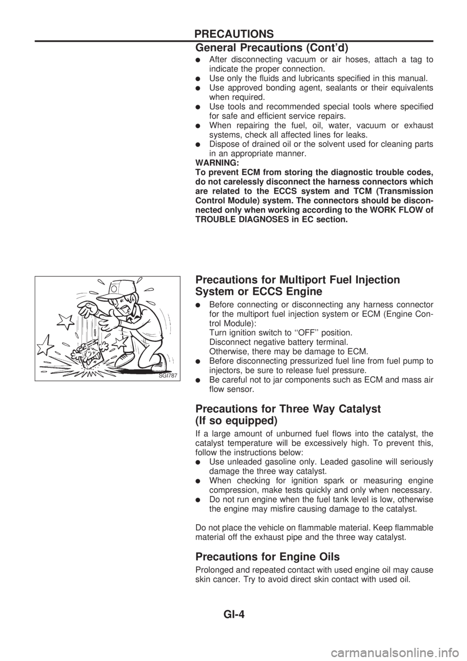
Precautions for Multiport Fuel Injection
System or ECCS Engine
lBefore connecting or disconnecting any harness connector
for the multiport fuel injection system or ECM (Engine Con-
trol Module):
Turn ignition switch to ``OFF'' position.
Disconnect negative battery terminal.
Otherwise, there may be damage to ECM.
lBefore disconnecting pressurized fuel line from fuel pump to
injectors, be sure to release fuel pressure.
lBe careful not to jar components such as ECM and mass air
flow sensor.
Precautions for Three Way Catalyst
(If so equipped)
If a large amount of unburned fuel flows into the catalyst, the
catalyst temperature will be excessively high. To prevent this,
follow the instructions below:
lUse unleaded gasoline only. Leaded gasoline will seriously
damage the three way catalyst.
lWhen checking for ignition spark or measuring engine
compression, make tests quickly and only when necessary.
lDo not run engine when the fuel tank level is low, otherwise
the engine may misfire causing damage to the catalyst.
Do not place the vehicle on flammable material. Keep flammable
material off the exhaust pipe and the three way catalyst.
Precautions for Engine Oils
Prolonged and repeated contact with used engine oil may cause
skin cancer. Try to avoid direct skin contact with used oil.
SGI787
PRECAUTIONS
General Precautions (Cont'd)
GI-4
Page 811 of 1659
lALPHABETICAL INDEXis provided at the end of this manual so that you can rapidly find the item and
page you are searching for.
lA QUICK REFERENCE INDEX,a black tab (e.g.) is provided on the first page. You can quickly
find the first page of each section by mating it to the section's black tab.
lTHE CONTENTSare listed on the first page of each section.
lTHE TITLEis indicated on the upper portion of each page and shows the part or system.
lTHE PAGE NUMBERof each section consists of two letters which designate the particular section and
a number (e.g. ``BR-5'').
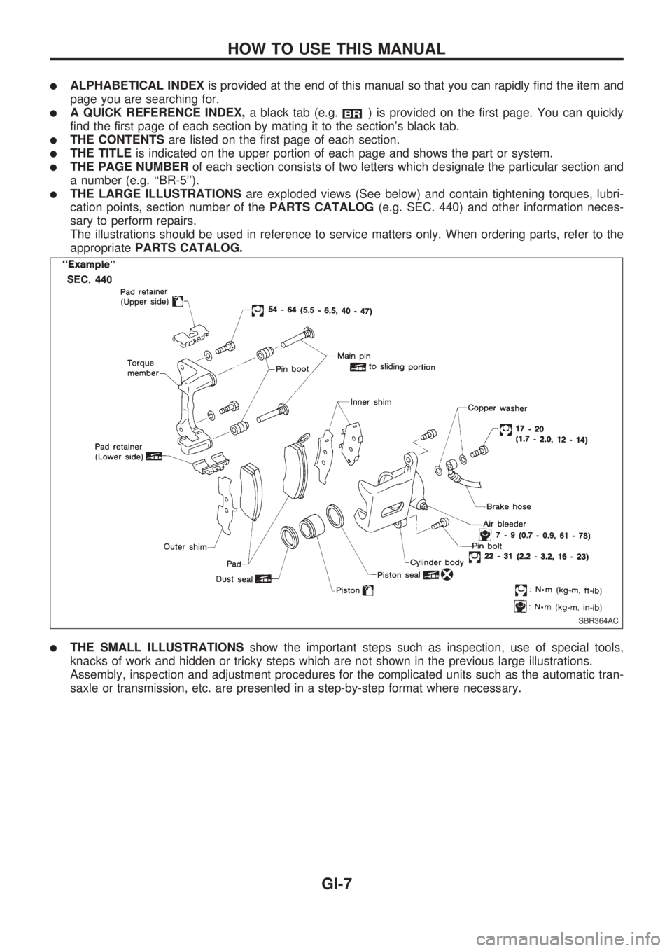
lTHE LARGE ILLUSTRATIONSare exploded views (See below) and contain tightening torques, lubri-
cation points, section number of thePARTS CATALOG(e.g. SEC. 440) and other information neces-
sary to perform repairs.
The illustrations should be used in reference to service matters only. When ordering parts, refer to the
appropriatePARTS CATALOG.
lTHE SMALL ILLUSTRATIONSshow the important steps such as inspection, use of special tools,
knacks of work and hidden or tricky steps which are not shown in the previous large illustrations.
Assembly, inspection and adjustment procedures for the complicated units such as the automatic tran-
saxle or transmission, etc. are presented in a step-by-step format where necessary.
SBR364AC
HOW TO USE THIS MANUAL
GI-7
Page 812 of 1659
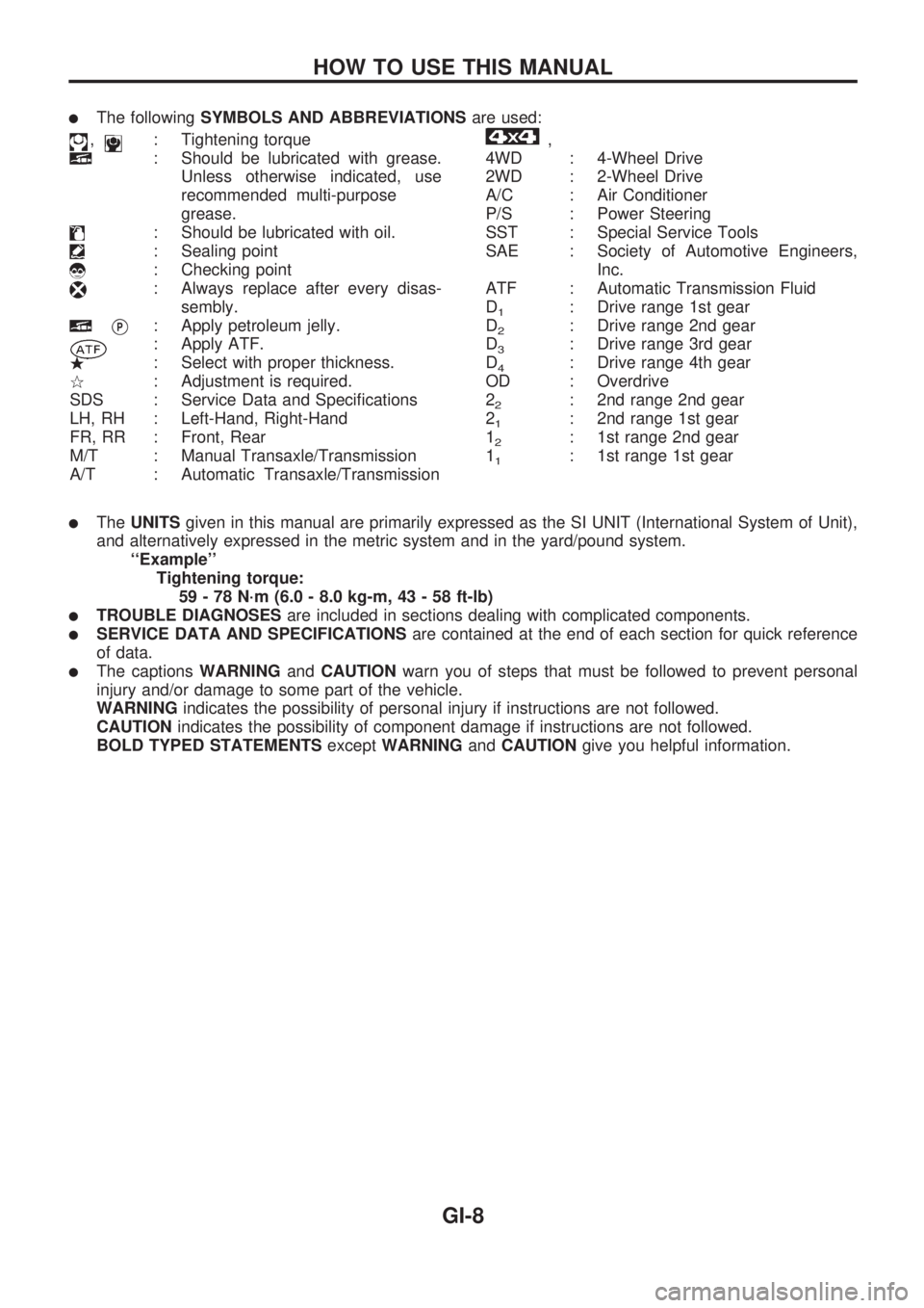
lThe followingSYMBOLS AND ABBREVIATIONSare used:
,: Tightening torque
: Should be lubricated with grease.
Unless otherwise indicated, use
recommended multi-purpose
grease.
: Should be lubricated with oil.
: Sealing point
: Checking point
: Always replace after every disas-
sembly.
VP: Apply petroleum jelly.
: Apply ATF.
.: Select with proper thickness.
>: Adjustment is required.
SDS : Service Data and Specifications
LH, RH : Left-Hand, Right-Hand
FR, RR : Front, Rear
M/T : Manual Transaxle/Transmission
A/T : Automatic Transaxle/Transmission
,
4WD : 4-Wheel Drive
2WD : 2-Wheel Drive
A/C : Air Conditioner
P/S : Power Steering
SST : Special Service Tools
SAE : Society of Automotive Engineers,
Inc.
ATF : Automatic Transmission Fluid
D
1: Drive range 1st gear
D
2: Drive range 2nd gear
D
3: Drive range 3rd gear
D
4: Drive range 4th gear
OD : Overdrive
2
2: 2nd range 2nd gear
2
1: 2nd range 1st gear
1
2: 1st range 2nd gear
1
1: 1st range 1st gear
lTheUNITSgiven in this manual are primarily expressed as the SI UNIT (International System of Unit),
and alternatively expressed in the metric system and in the yard/pound system.
``Example''
Tightening torque:
59 - 78 N´m (6.0 - 8.0 kg-m, 43 - 58 ft-lb)
lTROUBLE DIAGNOSESare included in sections dealing with complicated components.
lSERVICE DATA AND SPECIFICATIONSare contained at the end of each section for quick reference
of data.
lThe captionsWARNINGandCAUTIONwarn you of steps that must be followed to prevent personal
injury and/or damage to some part of the vehicle.
WARNINGindicates the possibility of personal injury if instructions are not followed.
CAUTIONindicates the possibility of component damage if instructions are not followed.
BOLD TYPED STATEMENTSexceptWARNINGandCAUTIONgive you helpful information.
HOW TO USE THIS MANUAL
GI-8
Page 825 of 1659
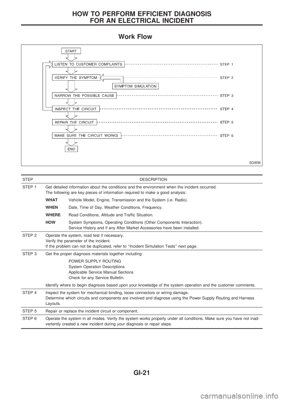
Work Flow
STEP DESCRIPTION
STEP 1 Get detailed information about the conditions and the environment when the incident occurred.
The following are key pieces of information required to make a good analysis:
WHATVehicle Model, Engine, Transmission and the System (i.e. Radio).
WHENDate, Time of Day, Weather Conditions, Frequency.
WHERERoad Conditions, Altitude and Traffic Situation.
HOWSystem Symptoms, Operating Conditions (Other Components Interaction).
Service History and if any After Market Accessories have been installed.
STEP 2 Operate the system, road test if necessary.
Verify the parameter of the incident.
If the problem can not be duplicated, refer to ``Incident Simulation Tests'' next page.
STEP 3 Get the proper diagnosis materials together including:
POWER SUPPLY ROUTING
System Operation Descriptions
Applicable Service Manual Sections
Check for any Service Bulletin.
Identify where to begin diagnosis based upon your knowledge of the system operation and the customer comments.
STEP 4 Inspect the system for mechanical binding, loose connectors or wiring damage.
Determine which circuits and components are involved and diagnose using the Power Supply Routing and Harness
Layouts.
STEP 5 Repair or replace the incident circuit or component.
STEP 6 Operate the system in all modes. Verify the system works properly under all conditions. Make sure you have not inad-
vertently created a new incident during your diagnosis or repair steps.
SGI838
HOW TO PERFORM EFFICIENT DIAGNOSIS
FOR AN ELECTRICAL INCIDENT
GI-21
Page 843 of 1659
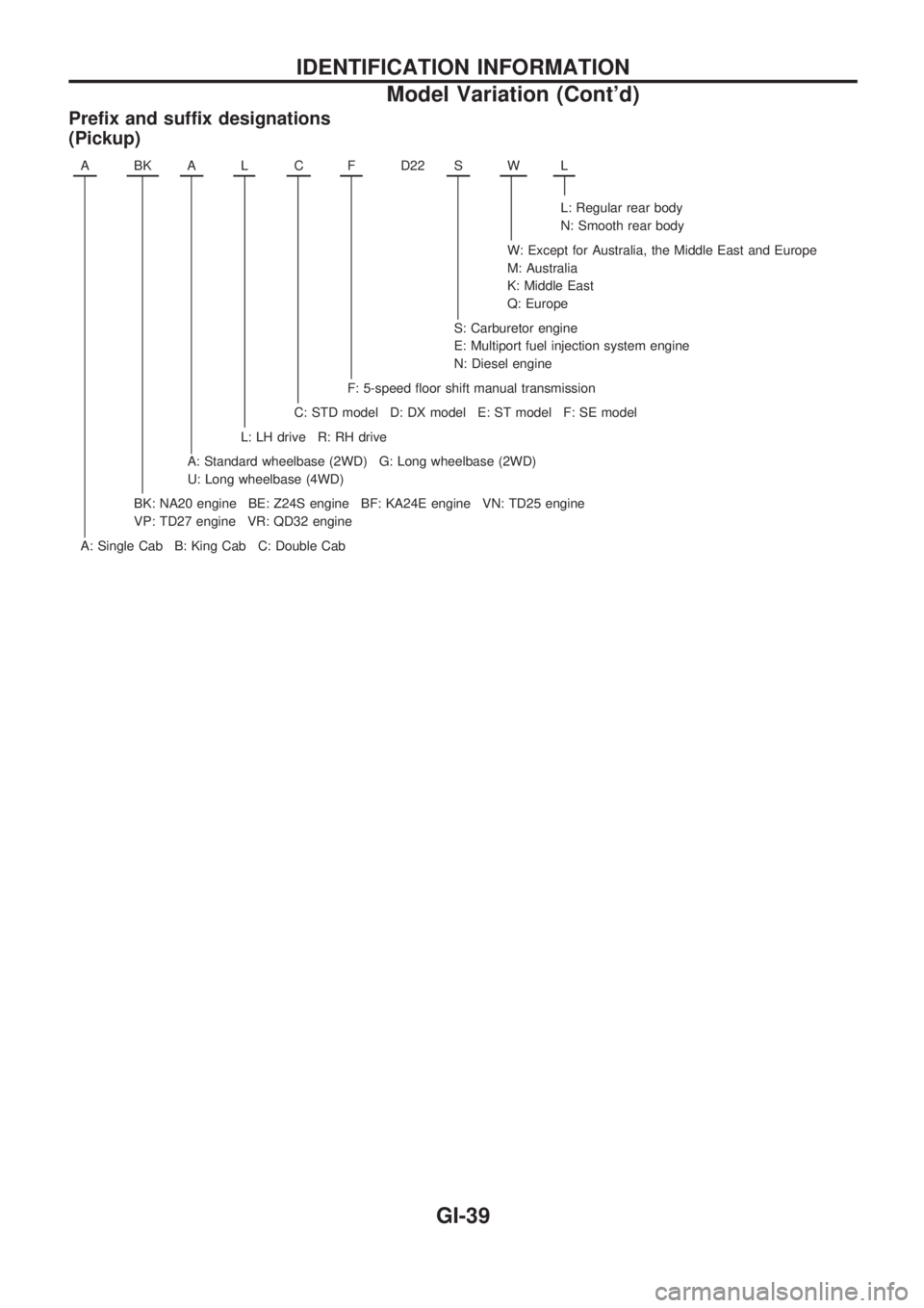
Prefix and suffix designations
(Pickup)
ABKALCFD22 SWL
L: Regular rear body
N: Smooth rear body
W: Except for Australia, the Middle East and Europe
M: Australia
K: Middle East
Q: Europe
S: Carburetor engine
E: Multiport fuel injection system engine
N: Diesel engine
F: 5-speed floor shift manual transmission
C: STD model D: DX model E: ST model F: SE model
L: LH drive R: RH drive
A: Standard wheelbase (2WD) G: Long wheelbase (2WD)
U: Long wheelbase (4WD)
BK: NA20 engine BE: Z24S engine BF: KA24E engine VN: TD25 engine
VP: TD27 engine VR: QD32 engine
A: Single Cab B: King Cab C: Double Cab
IDENTIFICATION INFORMATION
Model Variation (Cont'd)
GI-39
Page 868 of 1659
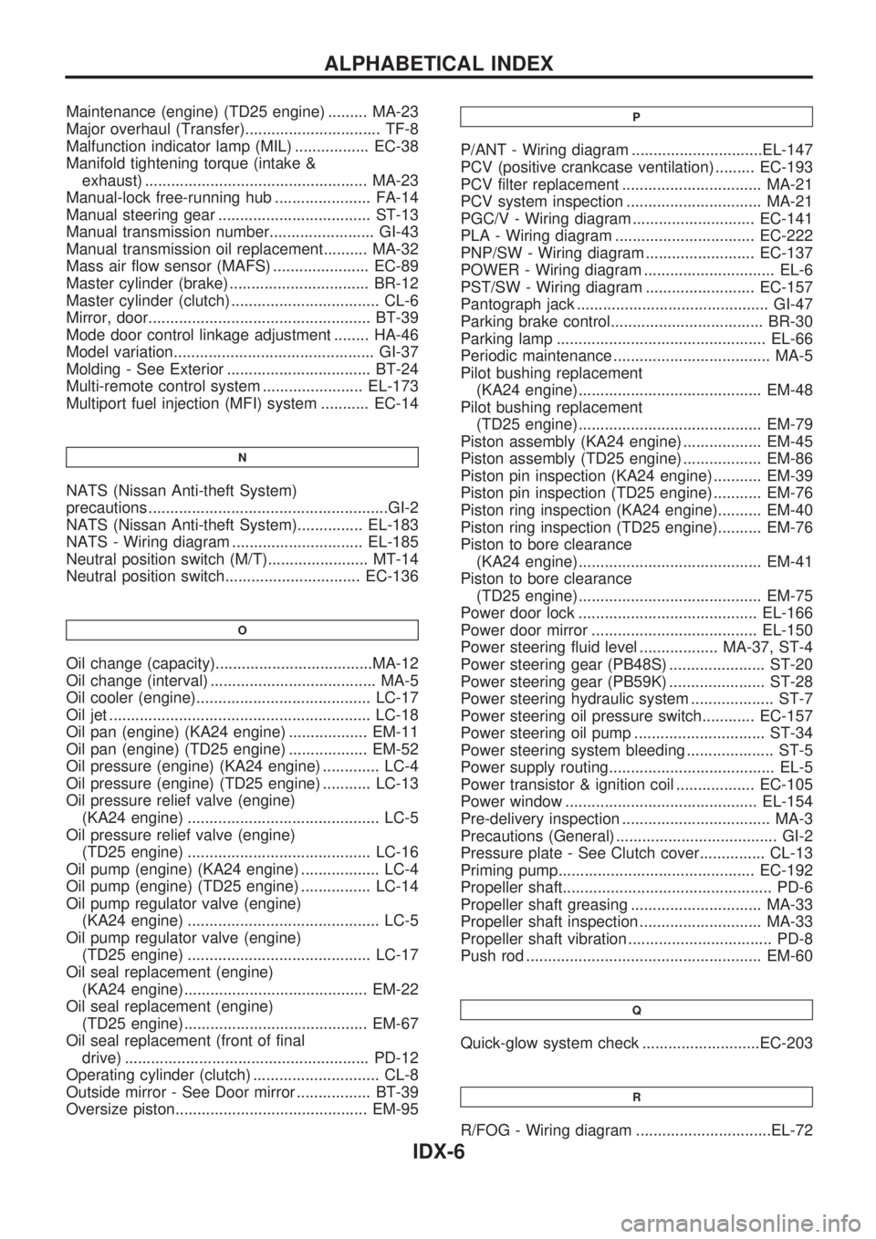
Maintenance (engine) (TD25 engine) ......... MA-23
Major overhaul (Transfer)............................... TF-8
Malfunction indicator lamp (MIL) ................. EC-38
Manifold tightening torque (intake &
exhaust) ................................................... MA-23
Manual-lock free-running hub ...................... FA-14
Manual steering gear ................................... ST-13
Manual transmission number........................ GI-43
Manual transmission oil replacement.......... MA-32
Mass air flow sensor (MAFS) ...................... EC-89
Master cylinder (brake) ................................ BR-12
Master cylinder (clutch) .................................. CL-6
Mirror, door................................................... BT-39
Mode door control linkage adjustment ........ HA-46
Model variation.............................................. GI-37
Molding - See Exterior ................................. BT-24
Multi-remote control system ....................... EL-173
Multiport fuel injection (MFI) system ........... EC-14
N
NATS (Nissan Anti-theft System)
precautions .......................................................GI-2
NATS (Nissan Anti-theft System)............... EL-183
NATS - Wiring diagram .............................. EL-185
Neutral position switch (M/T)....................... MT-14
Neutral position switch............................... EC-136
O
Oil change (capacity)....................................MA-12
Oil change (interval) ...................................... MA-5
Oil cooler (engine)........................................ LC-17
Oil jet ............................................................ LC-18
Oil pan (engine) (KA24 engine) .................. EM-11
Oil pan (engine) (TD25 engine) .................. EM-52
Oil pressure (engine) (KA24 engine) ............. LC-4
Oil pressure (engine) (TD25 engine) ........... LC-13
Oil pressure relief valve (engine)
(KA24 engine) ............................................ LC-5
Oil pressure relief valve (engine)
(TD25 engine) .......................................... LC-16
Oil pump (engine) (KA24 engine) .................. LC-4
Oil pump (engine) (TD25 engine) ................ LC-14
Oil pump regulator valve (engine)
(KA24 engine) ............................................ LC-5
Oil pump regulator valve (engine)
(TD25 engine) .......................................... LC-17
Oil seal replacement (engine)
(KA24 engine).......................................... EM-22
Oil seal replacement (engine)
(TD25 engine).......................................... EM-67
Oil seal replacement (front of final
drive) ........................................................ PD-12
Operating cylinder (clutch) ............................. CL-8
Outside mirror - See Door mirror ................. BT-39
Oversize piston............................................ EM-95
P
P/ANT - Wiring diagram ..............................EL-147
PCV (positive crankcase ventilation) ......... EC-193
PCV filter replacement ................................ MA-21
PCV system inspection ............................... MA-21
PGC/V - Wiring diagram ............................ EC-141
PLA - Wiring diagram ................................ EC-222
PNP/SW - Wiring diagram ......................... EC-137
POWER - Wiring diagram .............................. EL-6
PST/SW - Wiring diagram ......................... EC-157
Pantograph jack ............................................ GI-47
Parking brake control................................... BR-30
Parking lamp ................................................ EL-66
Periodic maintenance .................................... MA-5
Pilot bushing replacement
(KA24 engine).......................................... EM-48
Pilot bushing replacement
(TD25 engine).......................................... EM-79
Piston assembly (KA24 engine) .................. EM-45
Piston assembly (TD25 engine) .................. EM-86
Piston pin inspection (KA24 engine) ........... EM-39
Piston pin inspection (TD25 engine) ........... EM-76
Piston ring inspection (KA24 engine).......... EM-40
Piston ring inspection (TD25 engine).......... EM-76
Piston to bore clearance
(KA24 engine).......................................... EM-41
Piston to bore clearance
(TD25 engine).......................................... EM-75
Power door lock ......................................... EL-166
Power door mirror ...................................... EL-150
Power steering fluid level .................. MA-37, ST-4
Power steering gear (PB48S) ...................... ST-20
Power steering gear (PB59K) ...................... ST-28
Power steering hydraulic system ................... ST-7
Power steering oil pressure switch............ EC-157
Power steering oil pump .............................. ST-34
Power steering system bleeding .................... ST-5
Power supply routing...................................... EL-5
Power transistor & ignition coil .................. EC-105
Power window ............................................ EL-154
Pre-delivery inspection .................................. MA-3
Precautions (General) ..................................... GI-2
Pressure plate - See Clutch cover............... CL-13
Priming pump............................................. EC-192
Propeller shaft................................................ PD-6
Propeller shaft greasing .............................. MA-33
Propeller shaft inspection ............................ MA-33
Propeller shaft vibration ................................. PD-8
Push rod ...................................................... EM-60
Q
Quick-glow system check ...........................EC-203
R
R/FOG - Wiring diagram ...............................EL-72
ALPHABETICAL INDEX
IDX-6
Page 976 of 1659
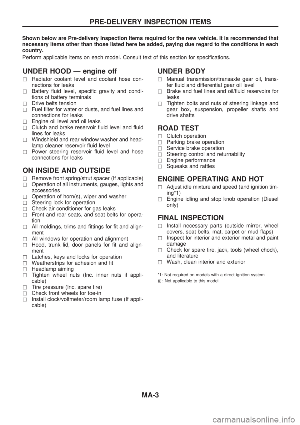
Shown below are Pre-delivery Inspection Items required for the new vehicle. It is recommended that
necessary items other than those listed here be added, paying due regard to the conditions in each
country.
Perform applicable items on each model. Consult text of this section for specifications.
UNDER HOOD Ð engine off
hRadiator coolant level and coolant hose con-
nections for leaks
hBattery fluid level, specific gravity and condi-
tions of battery terminals
hDrive belts tension
hFuel filter for water or dusts, and fuel lines and
connections for leaks
hEngine oil level and oil leaks
hClutch and brake reservoir fluid level and fluid
lines for leaks
hWindshield and rear window washer and head-
lamp cleaner reservoir fluid level
hPower steering reservoir fluid level and hose
connections for leaks
ON INSIDE AND OUTSIDE
hRemove front spring/strut spacer (If applicable)
hOperation of all instruments, gauges, lights and
accessories
hOperation of horn(s), wiper and washer
hSteering lock for operation
hCheck air conditioner for gas leaks
hFront and rear seats, and seat belts for opera-
tion
hAll moldings, trims and fittings for fit and align-
ment
hAll windows for operation and alignment
hHood, trunk lid, door panels for fit and align-
ment
hLatches, keys and locks for operation
hWeatherstrips for adhesion and fit
hHeadlamp aiming
hTighten wheel nuts (Inc. inner nuts if appli-
cable)
hTire pressure (Inc. spare tire)
hCheck front wheels for toe-in
hInstall clock/voltmeter/room lamp fuse (If appli-
cable)
UNDER BODY
hManual transmission/transaxle gear oil, trans-
fer fluid and differential gear oil level
hBrake and fuel lines and oil/fluid reservoirs for
leaks
hTighten bolts and nuts of steering linkage and
gear box, suspension, propeller shafts and
drive shafts
ROAD TEST
hClutch operation
hParking brake operation
hService brake operation
hSteering control and returnability
hEngine performance
hSqueaks and rattles
ENGINE OPERATING AND HOT
hAdjust idle mixture and speed (and ignition tim-
ing*1)
hEngine idling and stop knob operation (Diesel
only)
FINAL INSPECTION
hInstall necessary parts (outside mirror, wheel
covers, seat belts, mat, carpet or mud flaps)
hInspect for interior and exterior metal and paint
damage
hCheck for spare tire, jack, tools (wheel chock),
and literature
hWash, clean interior and exterior
*1: Not required on models with a direct ignition system
h
X: Not applicable to this model.
PRE-DELIVERY INSPECTION ITEMS
MA-3
Page 979 of 1659
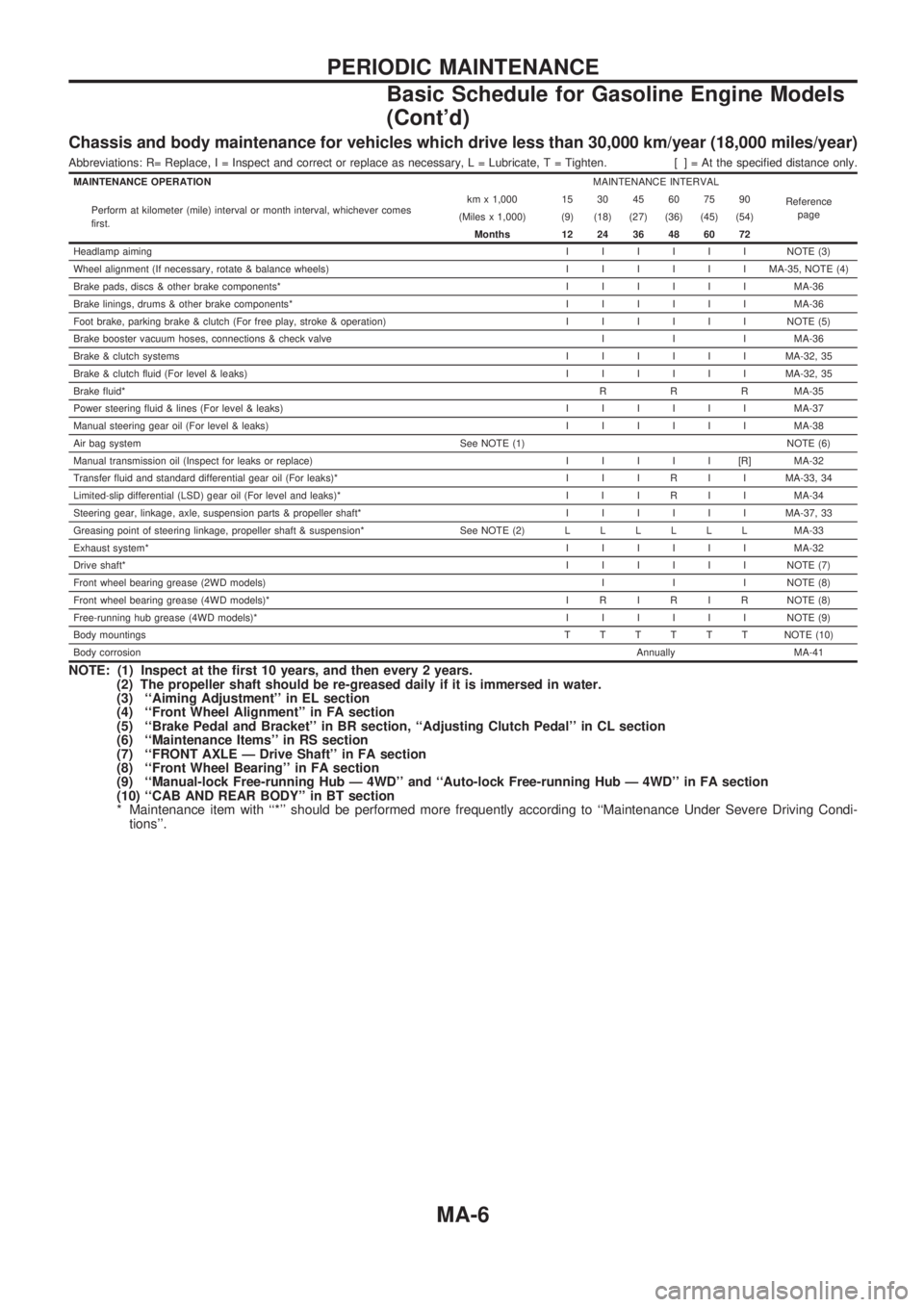
Chassis and body maintenance for vehicles which drive less than 30,000 km/year (18,000 miles/year)
Abbreviations: R= Replace, I = Inspect and correct or replace as necessary, L = Lubricate, T = Tighten. [ ] = At the specified distance only.
MAINTENANCE OPERATIONMAINTENANCE INTERVAL
Reference
page Perform at kilometer (mile) interval or month interval, whichever comes
first.km x 1,000 15 30 45 60 75 90
(Miles x 1,000) (9) (18) (27) (36) (45) (54)
Months 12 24 36 48 60 72
Headlamp aimingIIIIIINOTE (3)
Wheel alignment (If necessary, rotate & balance wheels)IIIIIIMA-35, NOTE (4)
Brake pads, discs & other brake components*IIIIIIMA-36
Brake linings, drums & other brake components*IIIIIIMA-36
Foot brake, parking brake & clutch (For free play, stroke & operation)IIIIIINOTE (5)
Brake booster vacuum hoses, connections & check valve I I I MA-36
Brake & clutch systemsIIIIIIMA-32, 35
Brake & clutch fluid (For level & leaks)IIIIIIMA-32, 35
Brake fluid*R R R MA-35
Power steering fluid & lines (For level & leaks)IIIIIIMA-37
Manual steering gear oil (For level & leaks)IIIIIIMA-38
Air bag system See NOTE (1) NOTE (6)
Manual transmission oil (Inspect for leaks or replace)IIIII[R]MA-32
Transfer fluid and standard differential gear oil (For leaks)* I I I R I I MA-33, 34
Limited-slip differential (LSD) gear oil (For level and leaks)* I I I R I I MA-34
Steering gear, linkage, axle, suspension parts & propeller shaft*IIIIIIMA-37, 33
Greasing point of steering linkage, propeller shaft & suspension* See NOTE (2)LLLLLLMA-33
Exhaust system*IIIIIIMA-32
Drive shaft*IIIIIINOTE (7)
Front wheel bearing grease (2WD models)I I I NOTE (8)
Front wheel bearing grease (4WD models)* I R I R I R NOTE (8)
Free-running hub grease (4WD models)*IIIIIINOTE (9)
Body mountingsTTTTTTNOTE (10)
Body corrosionAnnually MA-41
NOTE: (1) Inspect at the first 10 years, and then every 2 years.
(2) The propeller shaft should be re-greased daily if it is immersed in water.
(3) ``Aiming Adjustment'' in EL section
(4) ``Front Wheel Alignment'' in FA section
(5) ``Brake Pedal and Bracket'' in BR section, ``Adjusting Clutch Pedal'' in CL section
(6) ``Maintenance Items'' in RS section
(7) ``FRONT AXLE Ð Drive Shaft'' in FA section
(8) ``Front Wheel Bearing'' in FA section
(9) ``Manual-lock Free-running Hub Ð 4WD'' and ``Auto-lock Free-running Hub Ð 4WD'' in FA section
(10) ``CAB AND REAR BODY'' in BT section
* Maintenance item with ``*'' should be performed more frequently according to ``Maintenance Under Severe Driving Condi-
tions''.
PERIODIC MAINTENANCE
Basic Schedule for Gasoline Engine Models
(Cont'd)
MA-6
Page 980 of 1659
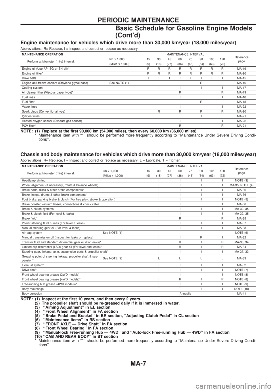
Engine maintenance for vehicles which drive more than 30,000 km/year (18,000 miles/year)
Abbreviations: R= Replace, I = Inspect and correct or replace as necessary.
MAINTENANCE OPERATIONMAINTENANCE INTERVAL
Reference
page
Perform at kilometer (mile) interval.km x 1,000 15 30 45 60 75 90 105 120
(Miles x 1,000) (9) (18) (27) (36) (45) (54) (63) (72)
Engine oil (Use API SG or SH oil)*RRRRRRRRMA-19
Engine oil filter*RRRRRRRRMA-20
Drive beltsIIIIIIIIMA-15
Engine anti-freeze coolant (Ethylene glycol base) See NOTE (1) R MA-16
Cooling systemIIIIMA-17
Air cleaner filter (Viscous paper type)*R R MA-19
Fuel linesI I MA-18
Fuel filter*R MA-18
Vapor linesI I MA-22
Spark plugs (Conventional type)RRRRMA-20
Ignition wiresI MA-21
Heated oxygen sensor (Exhaust gas sensor)I I MA-22
PCV filter*R R MA-21
NOTE: (1) Replace at the first 90,000 km (54,000 miles), then every 60,000 km (36,000 miles).
* Maintenance item with ``*'' should be performed more frequently according to ``Maintenance Under Severe Driving Condi-
tions''.
Chassis and body maintenance for vehicles which drive more than 30,000 km/year (18,000 miles/year)
Abbreviations: R= Replace, I = Inspect and correct or replace as necessary, L = Lubricate, T = Tighten.
MAINTENANCE OPERATIONMAINTENANCE INTERVAL
Reference
page
Perform at kilometer (mile) interval.km x 1,000 15 30 45 60 75 90 105 120
(Miles x 1,000) (9) (18) (27) (36) (45) (54) (63) (72)
Headlamp aimingIIIINOTE (3)
Wheel alignment (If necessary, rotate & balance wheels)IIIIMA-35, NOTE (4)
Brake pads, discs & other brake components*IIIIMA-36
Brake linings, drums & other brake components*IIIIMA-36
Foot brake, parking brake & clutch (For free play, stroke & operation)IIIINOTE (5)
Brake booster vacuum hoses, connections & check valve I I MA-36
Brake & clutch systemsIIIIMA-32, 35
Brake & clutch fluid (For level & leaks)IIIIMA-32, 35
Brake fluid*R R MA-35
Power steering fluid & lines (For level & leaks)IIIIMA-37
Manual steering gear oil (For level & leaks)IIIIMA-38
Air bag system See NOTE (1)NOTE (6)
Manual transmission oil (Inspect for leaks or replace) I I R I MA-32
Transfer fluid and standard differential gear oil (For leaks)* I R I R MA-33, 34
Limited-slip differential (LSD) gear oil (For level and leaks)* I R I R MA-34
Steering gear, linkage, axle, suspension parts & propeller shaft*IIIIMA-37, 33
Greasing point of steering linkage, propeller shaft & sus-
pension*See NOTE (2)LLLLMA-33
Exhaust system*IIIIMA-32
Drive shaft*IIIINOTE (7)
Front wheel bearing grease (2WD models)I I NOTE (8)
Front wheel bearing grease (4WD models)* I R I R NOTE (8)
Free-running hub grease (4WD models)*IIIINOTE (9)
Body mountingsTTTTNOTE (10)
Body corrosionAnnually MA-41
NOTE: (1) Inspect at the first 10 years, and then every 2 years.
(2) The propeller shaft should be re-greased daily if it is immersed in water.
(3) ``Aiming Adjustment'' in EL section
(4) ``Front Wheel Alignment'' in FA section
(5) ``Brake Pedal and Bracket'' in BR section, ``Adjusting Clutch Pedal'' in CL section
(6) ``Maintenance Items'' in RS section
(7) ``FRONT AXLE Ð Drive Shaft'' in FA section
(8) ``Front Wheel Bearing'' in FA section
(9) ``Manual-lock Free-running Hub Ð 4WD'' and ``Auto-lock Free-running Hub Ð 4WD'' in FA section
(10) ``CAB AND REAR BODY'' in BT section
* Maintenance item with ``*'' should be performed more frequently according to ``Maintenance Under Severe Driving Condi-
tions''.
PERIODIC MAINTENANCE
Basic Schedule for Gasoline Engine Models
(Cont'd)
MA-7
Page 981 of 1659
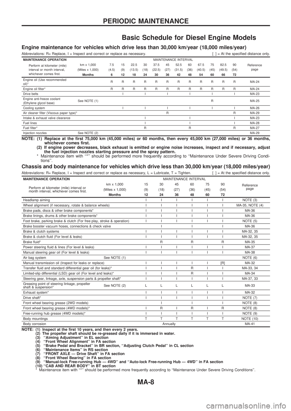
Basic Schedule for Diesel Engine Models
Engine maintenance for vehicles which drive less than 30,000 km/year (18,000 miles/year)
Abbreviations: R= Replace, I = Inspect and correct or replace as necessary. [ ] = At the specified distance only.
MAINTENANCE OPERATIONMAINTENANCE INTERVAL
Reference
page Perform at kilometer (mile)
interval or month interval,
whichever comes first.km x 1,000 7.5 15 22.5 30 37.5 45 52.5 60 67.5 75 82.5 90
(Miles x 1,000) (4.5) (9) (13.5) (18) (22.5) (27) (31.5) (36) (40.5) (45) (49.5) (54)
Months 6 12 18 24 30 36 42 48 54 60 66 72
Engine oil (Use recommended
oil)*RRRRRRRRRRRRMA-24
Engine oil filter*RRRRRRRRRRRRMA-24
Drive beltsIIIIIIMA-23
Engine anti-freeze coolant
(Ethylene glycol base)See NOTE (1)R MA-25
Cooling systemIIIIIIMA-26
Air cleaner filter (Viscous paper type)* R R MA-29
Intake & exhaust valve clearance I I I MA-23
Fuel linesI I I MA-28
Fuel filter*R R R MA-27
Injection nozzles See NOTE (2)MA-29
NOTE: (1) Replace at the first 75,000 km (45,000 miles) or 60 months, then every 45,000 km (27,000 miles) or 36 months,
whichever comes first.
(2) If engine power decreases, black exhaust is emitted or engine noise increases, inspect and if necessary, adjust
the fuel injection nozzles starting pressure and the spray pattern.
* Maintenance item with ``*'' should be performed more frequently according to ``Maintenance Under Severe Driving Condi-
tions''.
Chassis and body maintenance for vehicles which drive less than 30,000 km/year (18,000 miles/year)
Abbreviations: R= Replace, I = Inspect and correct or replace as necessary, L = Lubricate, T = Tighten. [ ] = At the specified distance only.
MAINTENANCE OPERATIONMAINTENANCE INTERVAL
Reference
page Perform at kilometer (mile) interval or
month interval, whichever comes first.km x 1,000 15 30 45 60 75 90
(Miles x 1,000) (9) (18) (27) (36) (45) (54)
Months 12 24 36 48 60 72
Headlamp aimingIIIIIINOTE (3)
Wheel alignment (if necessary, rotate & balance wheels)IIIIIIMA-35, NOTE (4)
Brake pads, discs & other brake components*IIIIIIMA-36
Brake linings, drums & other brake components*IIIIIIMA-36
Foot brake, parking brake & clutch (For free play, stroke & operation)IIIIIINOTE (5)
Brake booster vacuum hoses, connections & check valve I I I MA-36
Brake & clutch systemsIIIIIIMA-32, 35
Brake & clutch fluid (For level & leaks)IIIIIIMA-32, 35
Brake fluid*R R R MA-35
Power steering fluid & lines (For level & leaks)IIIIIIMA-37
Manual steering gear oil (For level & leaks)IIIIIIMA-38
Air bag system See NOTE (1)NOTE (6)
Manual transmission oil (Inspect for leaks or replace)IIIII[R]MA-32
Transfer fluid and standard differential gear oil (for leaks)* I I I R I I MA-33, 34
Limited-slip differential (LSD) gear oil (For level and leaks)* I I I R I I MA-34
Steering gear, linkage, axle, suspension parts & propeller shaft*IIIIIIMA-37, 33
Greasing point of steering linkage, propeller
shaft & suspension*See NOTE (2)LLLLLLMA-33
Exhaust system*IIIIIIMA-32
Drive shaft*IIIIIINOTE (7)
Front wheel bearing grease (2WD models) I I I NOTE (8)
Front wheel bearing grease (4WD models)* I R I R I R NOTE (8)
Free-running hub grease (4WD models)*IIIIIINOTE (9)
Body mountingsTTTTTTNOTE (10)
Body corrosionAnnually MA-41
NOTE: (1) Inspect at the first 10 years, and then every 2 years.
(2) The propeller shaft should be re-greased daily if it is immersed in water.
(3) ``Aiming Adjustment'' in EL section
(4) ``Front Wheel Alignment'' in FA section
(5) ``Brake Pedal and Bracket'' in BR section, ``Adjusting Clutch Pedal'' in CL section
(6) ``Maintenance Items'' in RS section
(7) ``FRONT AXLE Ð Drive Shaft'' in FA section
(8) ``Front Wheel Bearing'' in FA section
(9) ``Manual-lock Free-running Hub Ð 4WD'' and ``Auto-lock Free-running Hub Ð 4WD'' in FA section
(10) ``CAB AND REAR BODY'' in BT section
* Maintenance item with ``*'' should be performed more frequently according to ``Maintenance Under Severe Driving Conditions''.
PERIODIC MAINTENANCE
MA-8