battery NISSAN PICK-UP 1998 Service Manual
[x] Cancel search | Manufacturer: NISSAN, Model Year: 1998, Model line: PICK-UP, Model: NISSAN PICK-UP 1998Pages: 1659, PDF Size: 53.39 MB
Page 286 of 1659
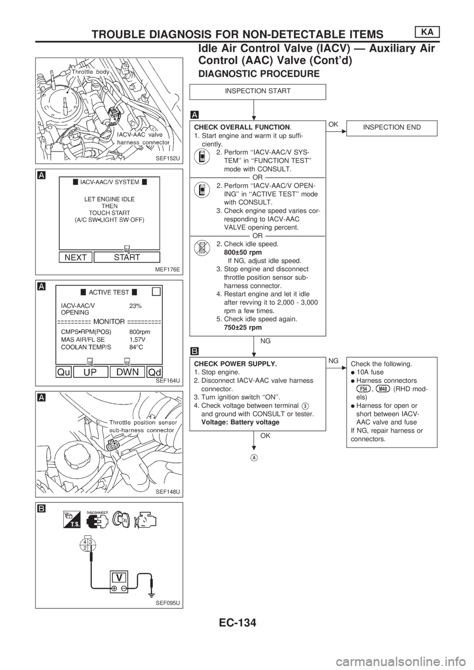
DIAGNOSTIC PROCEDURE
INSPECTION START
CHECK OVERALL FUNCTION.
1. Start engine and warm it up suffi-
ciently.
2. Perform ``IACV-AAC/V SYS-
TEM'' in ``FUNCTION TEST''
mode with CONSULT.
----------------------------------------------------------------------------------------------------------------------------------OR----------------------------------------------------------------------------------------------------------------------------------
2. Perform ``IACV-AAC/V OPEN-
ING'' in ``ACTIVE TEST'' mode
with CONSULT.
3. Check engine speed varies cor-
responding to IACV-AAC
VALVE opening percent.
----------------------------------------------------------------------------------------------------------------------------------OR----------------------------------------------------------------------------------------------------------------------------------
2. Check idle speed.
800 50 rpm
If NG, adjust idle speed.
3. Stop engine and disconnect
throttle position sensor sub-
harness connector.
4. Restart engine and let it idle
after revving it to 2,000 - 3,000
rpm a few times.
5. Check idle speed again.
750 25 rpm
NG
cOK
INSPECTION END
CHECK POWER SUPPLY.
1. Stop engine.
2. Disconnect IACV-AAC valve harness
connector.
3. Turn ignition switch ``ON''.
4. Check voltage between terminal
V3
and ground with CONSULT or tester.
Voltage: Battery voltage
OK
cNG
Check the following.
l10A fuse
lHarness connectorsF54,M48(RHD mod-
els)
lHarness for open or
short between IACV-
AAC valve and fuse
If NG, repair harness or
connectors.
VA
SEF152U
MEF176E
SEF164U
SEF148U
SEF095U
.
.
.
TROUBLE DIAGNOSIS FOR NON-DETECTABLE ITEMSKA
Idle Air Control Valve (IACV) Ð Auxiliary Air
Control (AAC) Valve (Cont'd)
EC-134
Page 292 of 1659
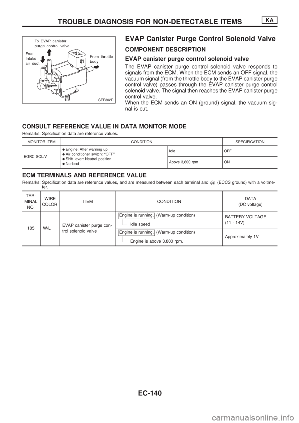
EVAP Canister Purge Control Solenoid Valve
COMPONENT DESCRIPTION
EVAP canister purge control solenoid valve
The EVAP canister purge control solenoid valve responds to
signals from the ECM. When the ECM sends an OFF signal, the
vacuum signal (from the throttle body to the EVAP canister purge
control valve) passes through the EVAP canister purge control
solenoid valve. The signal then reaches the EVAP canister purge
control valve.
When the ECM sends an ON (ground) signal, the vacuum sig-
nal is cut.
CONSULT REFERENCE VALUE IN DATA MONITOR MODE
Remarks: Specification data are reference values.
MONITOR ITEM CONDITION SPECIFICATION
EGRC SOL/V
lEngine: After warning uplAir conditioner switch: ``OFF''lShift lever: Neutral positionlNo-loadIdle OFF
Above 3,800 rpm ON
ECM TERMINALS AND REFERENCE VALUE
Remarks: Specification data are reference values, and are measured between each terminal andV39(ECCS ground) with a voltme-
ter.
TER-
MINAL
NO.WIRE
COLORITEM CONDITIONDATA
(DC voltage)
105 W/LEVAP canister purge con-
trol solenoid valveEngine is running.
(Warm-up condition)
Idle speedBATTERY VOLTAGE
(11 - 14V)
Engine is running.
(Warm-up condition)
Engine is above 3,800 rpm.Approximately 1V
SEF302R
TROUBLE DIAGNOSIS FOR NON-DETECTABLE ITEMSKA
EC-140
Page 294 of 1659
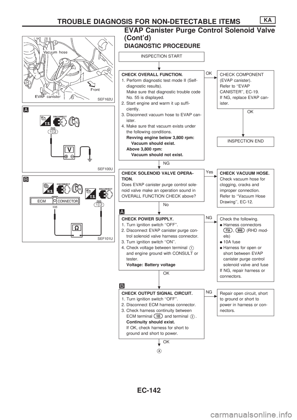
DIAGNOSTIC PROCEDURE
INSPECTION START
CHECK OVERALL FUNCTION.
1. Perform diagnostic test mode II (Self-
diagnostic results).
Make sure that diagnostic trouble code
No. 55 is displayed.
2. Start engine and warm it up suffi-
ciently.
3. Disconnect vacuum hose to EVAP can-
ister.
4. Make sure that vacuum exists under
the following conditions.
Revving engine below 3,800 rpm:
Vacuum should exist.
Above 3,800 rpm:
Vacuum should not exist.
NG
cOK
CHECK COMPONENT
(EVAP canister).
Refer to ``EVAP
CANISTER'', EC-19.
If NG, replace EVAP can-
ister.
OK
INSPECTION END
CHECK SOLENOID VALVE OPERA-
TION.
Does EVAP canister purge control sole-
noid valve make an operation sound in
OVERALL FUNCTION CHECK above?
No
cYes
CHECK VACUUM HOSE.
Check vacuum hose for
clogging, cracks and
improper connection.
Refer to ``Vacuum Hose
Drawing'', EC-12.
CHECK POWER SUPPLY.
1. Turn ignition switch ``OFF''.
2. Disconnect EVAP canister purge con-
trol solenoid valve harness connector.
3. Turn ignition switch ``ON''.
4. Check voltage between terminal
V1
and engine ground with CONSULT or
tester.
Voltage: Battery voltage
OK
cNG
Check the following.
lHarness connectors
F54,M48(RHD mod-
els)
l10A fuse
lHarness for open or
short between EVAP
canister purge control
solenoid valve and fuse
If NG, repair harness or
connectors.
CHECK OUTPUT SIGNAL CIRCUIT.
1. Turn ignition switch ``OFF''.
2. Disconnect ECM harness connector.
3. Check harness continuity between
ECM terminal
105and terminalV2.
Continuity should exist.
If OK, check harness for short to
ground and short to power.
OK
cNG
Repair open circuit, short
to ground or short to
power in harness or con-
nectors.
VA
SEF162U
SEF100U
SEF101U
.
.
.
.
.
.
TROUBLE DIAGNOSIS FOR NON-DETECTABLE ITEMSKA
EVAP Canister Purge Control Solenoid Valve
(Cont'd)
EC-142
Page 298 of 1659
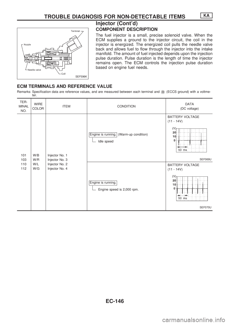
COMPONENT DESCRIPTION
The fuel injector is a small, precise solenoid valve. When the
ECM supplies a ground to the injector circuit, the coil in the
injector is energized. The energized coil pulls the needle valve
back and allows fuel to flow through the injector into the intake
manifold. The amount of fuel injected depends upon the injection
pulse duration. Pulse duration is the length of time the injector
remains open. The ECM controls the injection pulse duration
based on engine fuel needs.
ECM TERMINALS AND REFERENCE VALUE
Remarks: Specification data are reference values, and are measured between each terminal andV39(ECCS ground) with a voltme-
ter.
TER-
MINAL
NO.WIRE
COLORITEM CONDITIONDATA
(DC voltage)
101
103
110
112W/B
W/R
W/L
W/GInjector No. 1
Injector No. 3
Injector No. 2
Injector No. 4Engine is running.
(Warm-up condition)
Idle speedBATTERY VOLTAGE
(11 - 14V)
SEF069U
Engine is running.
Engine speed is 2,000 rpm.BATTERY VOLTAGE
(11 - 14V)
SEF070U
SEF596K
TROUBLE DIAGNOSIS FOR NON-DETECTABLE ITEMSKA
Injector (Cont'd)
EC-146
Page 299 of 1659
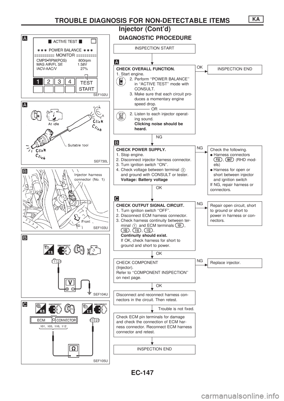
DIAGNOSTIC PROCEDURE
INSPECTION START
CHECK OVERALL FUNCTION.
1. Start engine.
2. Perform ``POWER BALANCE''
in ``ACTIVE TEST'' mode with
CONSULT.
3. Make sure that each circuit pro-
duces a momentary engine
speed drop.
----------------------------------------------------------------------------------------------------------------------------------OR----------------------------------------------------------------------------------------------------------------------------------
2. Listen to each injector operat-
ing sound.
Clicking noise should be
heard.
NG
cOK
INSPECTION END
CHECK POWER SUPPLY.
1. Stop engine.
2. Disconnect injector harness connector.
3. Turn ignition switch ``ON''.
4. Check voltage between terminal
V2
and ground with CONSULT or tester.
Voltage: Battery voltage
OK
cNG
Check the following.
lHarness connectorsF55,M47(RHD mod-
els)
lHarness for open or
short between injector
and ignition switch
If NG, repair harness or
connectors.
CHECK OUTPUT SIGNAL CIRCUIT.
1. Turn ignition switch ``OFF''.
2. Disconnect ECM harness connector.
3. Check harness continuity between ter-
minal
V1and ECM terminals101,103,110,112.
Continuity should exist.
If OK, check harness for short to
ground and short to power.
OK
cNG
Repair open circuit, short
to ground or short to
power in harness or con-
nectors.
CHECK COMPONENT
(Injector).
Refer to ``COMPONENT INSPECTION''
on next page.
OK
cNG
Replace injector.
Disconnect and reconnect harness con-
nectors in the circuit. Then retest.
Trouble is not fixed.
Check ECM pin terminals for damage
and check the connection of ECM har-
ness connector. Reconnect ECM harness
connector and retest.
INSPECTION END
SEF102U
SEF730L
SEF103U
SEF104U
SEF105U
.
.
.
.
.
.
.
TROUBLE DIAGNOSIS FOR NON-DETECTABLE ITEMSKA
Injector (Cont'd)
EC-147
Page 302 of 1659

DIAGNOSTIC PROCEDURE
INSPECTION START
CHECK OVERALL FUNCTION.
1. Turn ignition switch ``ON''.
2. Perform ``START SIGNAL CKT''
in ``FUNCTION TEST'' mode
with CONSULT.
----------------------------------------------------------------------------------------------------------------------------------OR----------------------------------------------------------------------------------------------------------------------------------
1. Turn ignition switch ``ON''.
2. Check ``START SIGNAL'' in
``DATA MONITOR'' mode with
CONSULT.
----------------------------------------------------------------------------------------------------------------------------------OR----------------------------------------------------------------------------------------------------------------------------------
1. Turn ignition switch to
``START''.
2. Check voltage between ECM
terminal
V34and ground.
Voltage:
Ignition switch ``START''
Battery voltage
Except above
Approximately 0V
NG
cOK
INSPECTION END
Check if 7.5A fuse is OK.
OK
cNG
Replace 7.5A fuse.
CHECK INPUT SIGNAL CIRCUIT.
1. Turn ignition switch ``OFF''.
2. Disconnect ECM harness connector
and 7.5A fuse.
3. Check harness continuity between
ECM terminal
V34and fuse block.
Continuity should exist.
If OK, check harness for short to
ground and short to power.
OK
cNG
Check the following.
lHarness connectorsF54,M48(RHD mod-
els)
lHarness for open or
short between ECM and
fuse block
If NG, repair open circuit,
short to ground or short to
power in harness or con-
nectors.
Disconnect and reconnect harness con-
nectors in the circuit. Then retest.
Trouble is not fixed.
Check ECM pin terminals for damage
and check the connection of ECM har-
ness connector. Reconnect ECM harness
connector and retest.
INSPECTION END
IGN ``ON'' OFF
IGN ``START'' ON
SEF191L
SEF153U
SEF107U
SEF108U
.
.
.
.
.
.
TROUBLE DIAGNOSIS FOR NON-DETECTABLE ITEMSKA
Start Signal (Cont'd)
EC-150
Page 304 of 1659

ECM TERMINALS AND REFERENCE VALUE
Remarks: Specification data are reference values, and are measured between each terminal andV39(ECCS ground) with a voltme-
ter.
TER-
MINAL
NO.WIRE
COLORITEM CONDITIONDATA
(DC voltage)
104 W/R Fuel pump relayIgnition switch ``ON''
For 5 seconds after turning ignition switch
``ON''
Engine is running.Approximately 1V
Ignition switch ``ON''
5 seconds after turning ignition switch ``ON''BATTERY VOLTAGE
(11 - 14V)
TROUBLE DIAGNOSIS FOR NON-DETECTABLE ITEMSKA
Fuel Pump (Cont'd)
EC-152
Page 307 of 1659

DIAGNOSTIC PROCEDURE
INSPECTION START
CHECK OVERALL FUNCTION.
1. Turn ignition switch ``ON''.
2. Pinch fuel feed hose with fingers.
Fuel pressure pulsation should be
felt on the fuel feed hose for 5 sec-
onds after ignition switch is turned
``ON''.
NG
cOK
INSPECTION END
CHECK POWER SUPPLY.
1. Turn ignition switch ``OFF''.
2. Disconnect fuel pump relay.
3. Turn ignition switch ``ON''.
4. Check voltage between terminals
V1,
V3and ground with CONSULT or
tester.
Voltage: Battery voltage
OK
cNG
Check the following.
l15A fuse
lHarness connectorsE101,M5
lHarness for open or
short between fuse and
fuel pump relay
If NG, repair harness or
connectors.
CHECK GROUND CIRCUIT.
1. Turn ignition switch ``OFF''.
2. Disconnect fuel pump harness connec-
tor.
3. Check harness continuity between ter-
minal
V6and body ground, relay ter-
minal
V5and terminalV5.
Continuity should exist.
If OK, check harness for short to
ground and short to power.
OK
cNG
Check the following.
lHarness connectorsC9,M121(LHD mod-
els for Europe)
lHarness connectorsE101,M5
lHarness for open or
short between fuel pump
and body ground
lHarness for open or
short between fuel pump
and fuel pump relay
If NG, repair open circuit,
short to ground or short to
power in harness or con-
nectors.
CHECK OUTPUT SIGNAL CIRCUIT.
1. Disconnect ECM harness connector.
2. Check harness continuity between
ECM terminal
104and terminalV2.
Continuity should exist.
If OK, check harness for short to
ground and short to power.
OK
cNG
Check the following.
lHarness connectorsE101,M5
lHarness connectorsM48,F54(RHD mod-
els)
lHarness for open or
short between ECM and
fuel pump relay
If NG, repair open circuit,
short to ground or short to
power in harness or con-
nectors.
VA
(Go to next page.)
SEF109U
SEF110U
SEF479P
SEF154U
.
.
.
.
.
TROUBLE DIAGNOSIS FOR NON-DETECTABLE ITEMSKA
Fuel Pump (Cont'd)
EC-155
Page 313 of 1659
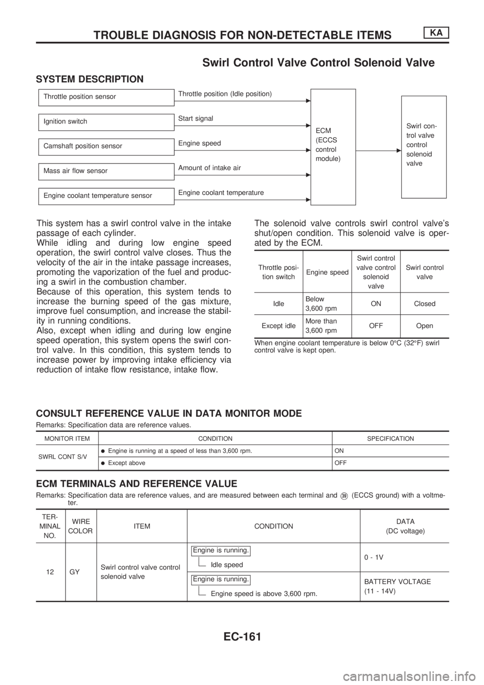
Swirl Control Valve Control Solenoid Valve
SYSTEM DESCRIPTION
Throttle position sensorcThrottle position (Idle position)
ECM
(ECCS
control
module)
c
Swirl con-
trol valve
control
solenoid
valveIgnition switchcStart signal
Camshaft position sensor
cEngine speed
Mass air flow sensor
cAmount of intake air
Engine coolant temperature sensor
cEngine coolant temperature
This system has a swirl control valve in the intake
passage of each cylinder.
While idling and during low engine speed
operation, the swirl control valve closes. Thus the
velocity of the air in the intake passage increases,
promoting the vaporization of the fuel and produc-
ing a swirl in the combustion chamber.
Because of this operation, this system tends to
increase the burning speed of the gas mixture,
improve fuel consumption, and increase the stabil-
ity in running conditions.
Also, except when idling and during low engine
speed operation, this system opens the swirl con-
trol valve. In this condition, this system tends to
increase power by improving intake efficiency via
reduction of intake flow resistance, intake flow.The solenoid valve controls swirl control valve's
shut/open condition. This solenoid valve is oper-
ated by the ECM.
Throttle posi-
tion switchEngine speedSwirl control
valve control
solenoid
valveSwirl control
valve
IdleBelow
3,600 rpmON Closed
Except idleMore than
3,600 rpmOFF Open
When engine coolant temperature is below 0ÉC (32ÉF) swirl
control valve is kept open.
CONSULT REFERENCE VALUE IN DATA MONITOR MODE
Remarks: Specification data are reference values.
MONITOR ITEM CONDITION SPECIFICATION
SWRL CONT S/V
lEngine is running at a speed of less than 3,600 rpm. ON
lExcept above OFF
ECM TERMINALS AND REFERENCE VALUE
Remarks: Specification data are reference values, and are measured between each terminal andV39(ECCS ground) with a voltme-
ter.
TER-
MINAL
NO.WIRE
COLORITEM CONDITIONDATA
(DC voltage)
12 GYSwirl control valve control
solenoid valveEngine is running.
Idle speed0-1V
Engine is running.
Engine speed is above 3,600 rpm.BATTERY VOLTAGE
(11 - 14V)
TROUBLE DIAGNOSIS FOR NON-DETECTABLE ITEMSKA
EC-161
Page 317 of 1659
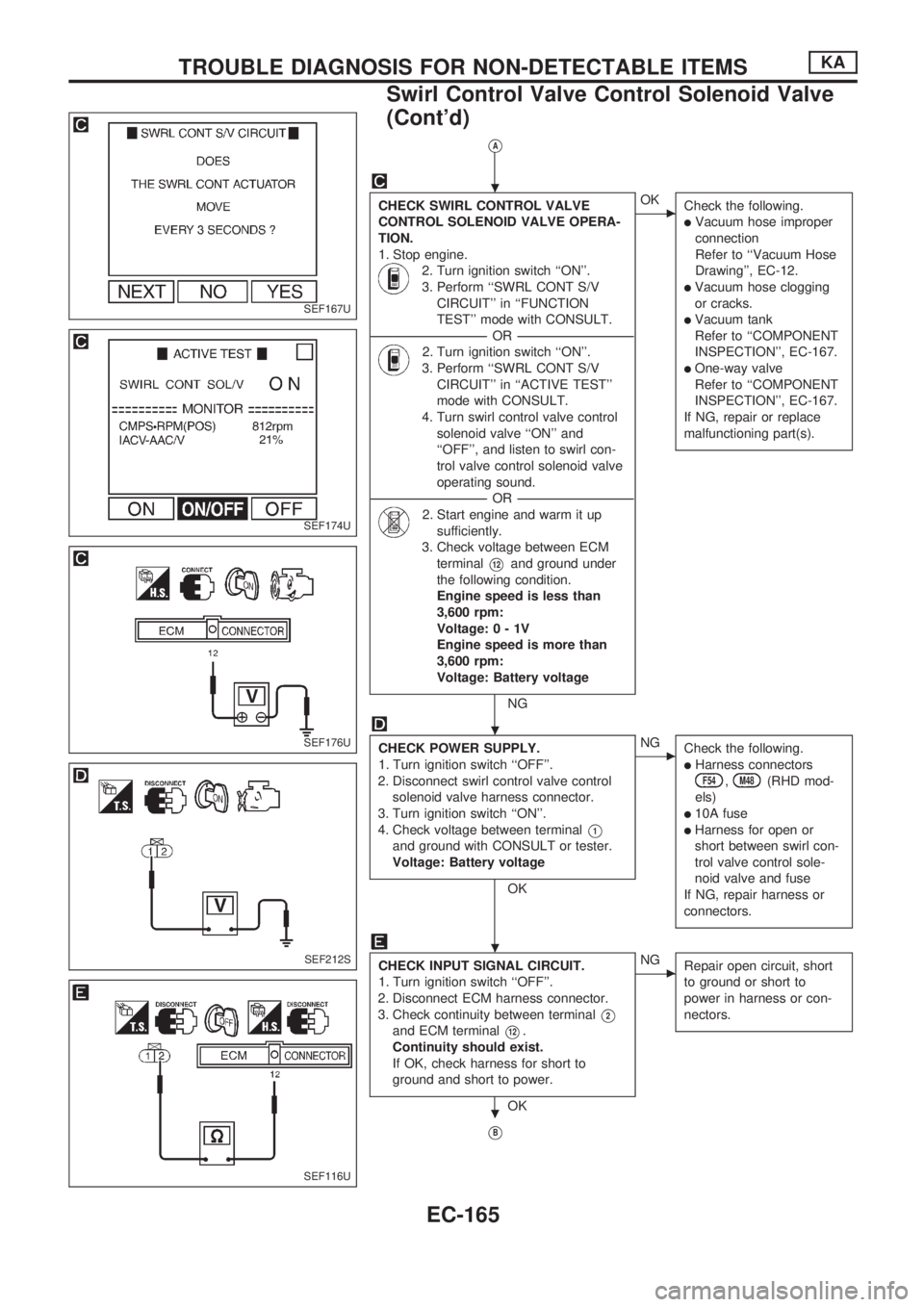
VA
CHECK SWIRL CONTROL VALVE
CONTROL SOLENOID VALVE OPERA-
TION.
1. Stop engine.
2. Turn ignition switch ``ON''.
3. Perform ``SWRL CONT S/V
CIRCUIT'' in ``FUNCTION
TEST'' mode with CONSULT.
----------------------------------------------------------------------------------------------------------------------------------OR----------------------------------------------------------------------------------------------------------------------------------
2. Turn ignition switch ``ON''.
3. Perform ``SWRL CONT S/V
CIRCUIT'' in ``ACTIVE TEST''
mode with CONSULT.
4. Turn swirl control valve control
solenoid valve ``ON'' and
``OFF'', and listen to swirl con-
trol valve control solenoid valve
operating sound.
----------------------------------------------------------------------------------------------------------------------------------OR----------------------------------------------------------------------------------------------------------------------------------
2. Start engine and warm it up
sufficiently.
3. Check voltage between ECM
terminal
V12and ground under
the following condition.
Engine speed is less than
3,600 rpm:
Voltage:0-1V
Engine speed is more than
3,600 rpm:
Voltage: Battery voltage
NG
cOK
Check the following.
lVacuum hose improper
connection
Refer to ``Vacuum Hose
Drawing'', EC-12.
lVacuum hose clogging
or cracks.
lVacuum tank
Refer to ``COMPONENT
INSPECTION'', EC-167.
lOne-way valve
Refer to ``COMPONENT
INSPECTION'', EC-167.
If NG, repair or replace
malfunctioning part(s).
CHECK POWER SUPPLY.
1. Turn ignition switch ``OFF''.
2. Disconnect swirl control valve control
solenoid valve harness connector.
3. Turn ignition switch ``ON''.
4. Check voltage between terminal
V1
and ground with CONSULT or tester.
Voltage: Battery voltage
OK
cNG
Check the following.
lHarness connectorsF54,M48(RHD mod-
els)
l10A fuse
lHarness for open or
short between swirl con-
trol valve control sole-
noid valve and fuse
If NG, repair harness or
connectors.
CHECK INPUT SIGNAL CIRCUIT.
1. Turn ignition switch ``OFF''.
2. Disconnect ECM harness connector.
3. Check continuity between terminal
V2
and ECM terminalV12.
Continuity should exist.
If OK, check harness for short to
ground and short to power.
OK
cNG
Repair open circuit, short
to ground or short to
power in harness or con-
nectors.
VB
SEF167U
SEF174U
SEF176U
SEF212S
SEF116U
.
.
.
.
TROUBLE DIAGNOSIS FOR NON-DETECTABLE ITEMSKA
Swirl Control Valve Control Solenoid Valve
(Cont'd)
EC-165