battery NISSAN PICK-UP 1998 User Guide
[x] Cancel search | Manufacturer: NISSAN, Model Year: 1998, Model line: PICK-UP, Model: NISSAN PICK-UP 1998Pages: 1659, PDF Size: 53.39 MB
Page 79 of 1659
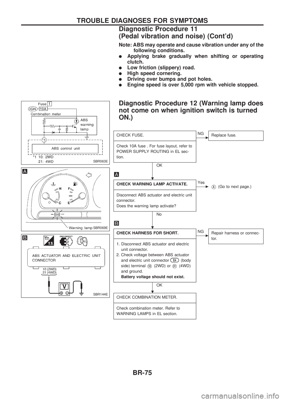
Note: ABS may operate and cause vibration under any of the
following conditions.
lApplying brake gradually when shifting or operating
clutch.
lLow friction (slippery) road.
lHigh speed cornering.
lDriving over bumps and pot holes.
lEngine speed is over 5,000 rpm with vehicle stopped.
Diagnostic Procedure 12 (Warning lamp does
not come on when ignition switch is turned
ON.)
CHECK FUSE.
-------------------------------------------------------------------------------------------------------------------------------------------------------------------------------------------------------------------------------------------------------------------------------------------------------------
Check 10A fuse . For fuse layout, refer to
POWER SUPPLY ROUTING in EL sec-
tion.
OK
cNG
Replace fuse.
CHECK WARNING LAMP ACTIVATE.
-------------------------------------------------------------------------------------------------------------------------------------------------------------------------------------------------------------------------------------------------------------------------------------------------------------
Disconnect ABS actuator and electric unit
connector.
Does the warning lamp activate?
No
cYes
VA(Go to next page.)
CHECK HARNESS FOR SHORT.
-------------------------------------------------------------------------------------------------------------------------------------------------------------------------------------------------------------------------------------------------------------------------------------------------------------
1. Disconnect ABS actuator and electric
unit connector.
2. Check voltage between ABS actuator
and electric unit connector
E4(body
side) terminal
V10(2WD) orV21(4WD)
and ground.
Battery voltage should not exist.
OK
cNG
Repair harness or connec-
tor.
CHECK COMBINATION METER.
-------------------------------------------------------------------------------------------------------------------------------------------------------------------------------------------------------------------------------------------------------------------------------------------------------------
Check combination meter. Refer to
WARNING LAMPS in EL section.
SBR063E
SBR069E
SBR144E
.
.
.
TROUBLE DIAGNOSES FOR SYMPTOMS
Diagnostic Procedure 11
(Pedal vibration and noise) (Cont'd)
BR-75
Page 112 of 1659
CAUTION:
lDisconnect both terminals from battery in advance.
lDisconnect air bag module connector in advance.
lBe careful not to scratch finishers and other parts.
lNever tamper with or force air bag lid open, as this may adversely affect air bag performance.
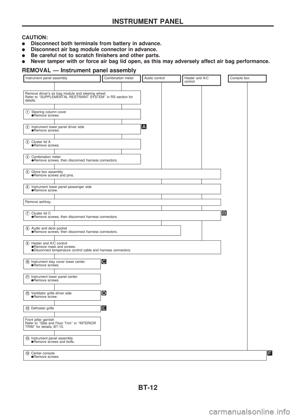
REMOVAL Ð Instrument panel assembly
Instrument panel assemblyCombination meterAudio controlHeater and A/C
controlConsole box
Remove driver's air bag module and steering wheel.
Refer to ``SUPPLEMENTAL RESTRAINT SYSTEM'' in RS section for
details.
V1Steering column coverlRemove screws.
V2Instrument lower panel driver sidelRemove screws.
V3Cluster lid AlRemove screws.
V4Combination meterlRemove screws, then disconnect harness connectors.
V5Glove box assemblylRemove screws and pins.
V6Instrument lower panel passenger sidelRemove screw.
Remove ashtray.
V7Cluster lid ClRemove screws, then disconnect harness connectors.
V8Audio and deck pocketlRemove screws, then disconnect harness connectors.
V9Heater and A/C controllRemove mask and screws.lDisconnect temperature control cable and harness connectors.
V10Instrument stay cover lower centerlRemove screws.
V11Instrument lower panel centerlRemove screws.
V12Ventilator grille driver sidelRemove screw.
V13Defroster grille
Front pillar garnish
Refer to ``Side and Floor Trim'' in ``INTERIOR
TRIM'' for details, BT-15.
V14Instrument panel assemblylRemove screws and bolts.
V15Center consolelRemove screws.
INSTRUMENT PANEL
BT-12
Page 158 of 1659
Precautions
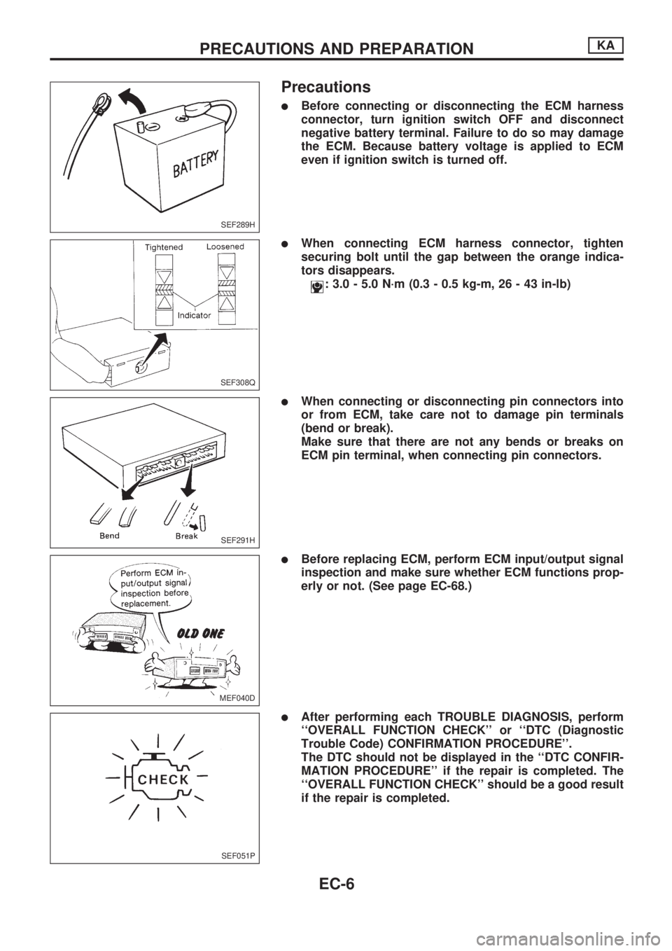
lBefore connecting or disconnecting the ECM harness
connector, turn ignition switch OFF and disconnect
negative battery terminal. Failure to do so may damage
the ECM. Because battery voltage is applied to ECM
even if ignition switch is turned off.
lWhen connecting ECM harness connector, tighten
securing bolt until the gap between the orange indica-
tors disappears.
: 3.0 - 5.0 N´m (0.3 - 0.5 kg-m, 26 - 43 in-lb)
lWhen connecting or disconnecting pin connectors into
or from ECM, take care not to damage pin terminals
(bend or break).
Make sure that there are not any bends or breaks on
ECM pin terminal, when connecting pin connectors.
lBefore replacing ECM, perform ECM input/output signal
inspection and make sure whether ECM functions prop-
erly or not. (See page EC-68.)
lAfter performing each TROUBLE DIAGNOSIS, perform
``OVERALL FUNCTION CHECK'' or ``DTC (Diagnostic
Trouble Code) CONFIRMATION PROCEDURE''.
The DTC should not be displayed in the ``DTC CONFIR-
MATION PROCEDURE'' if the repair is completed. The
``OVERALL FUNCTION CHECK'' should be a good result
if the repair is completed.
SEF289H
SEF308Q
SEF291H
MEF040D
SEF051P
PRECAUTIONS AND PREPARATIONKA
EC-6
Page 165 of 1659
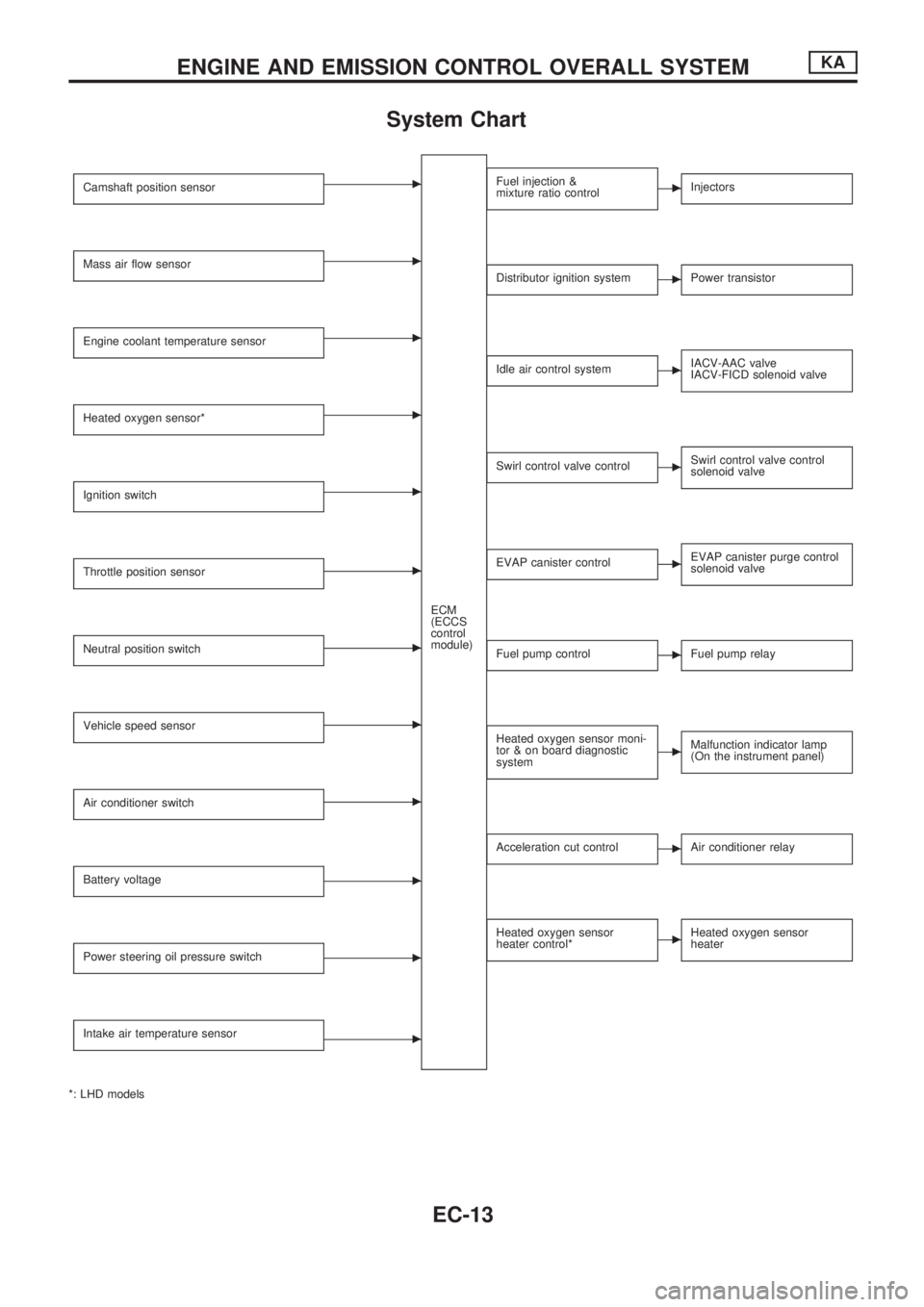
System Chart
Camshaft position sensorc
ECM
(ECCS
control
module)
Mass air flow sensorc
Engine coolant temperature sensorc
Heated oxygen sensor*c
Ignition switchc
Throttle position sensorc
Neutral position switchc
Vehicle speed sensorc
Air conditioner switchc
Battery voltagec
Power steering oil pressure switchc
Intake air temperature sensorc
*: LHD models
Fuel injection &
mixture ratio controlcInjectors
Distributor ignition systemcPower transistor
Idle air control systemcIACV-AAC valve
IACV-FICD solenoid valve
Swirl control valve controlcSwirl control valve control
solenoid valve
EVAP canister controlcEVAP canister purge control
solenoid valve
Fuel pump controlcFuel pump relay
Heated oxygen sensor moni-
tor & on board diagnostic
systemcMalfunction indicator lamp
(On the instrument panel)
Acceleration cut controlcAir conditioner relay
Heated oxygen sensor
heater control*cHeated oxygen sensor
heater
ENGINE AND EMISSION CONTROL OVERALL SYSTEMKA
EC-13
Page 166 of 1659
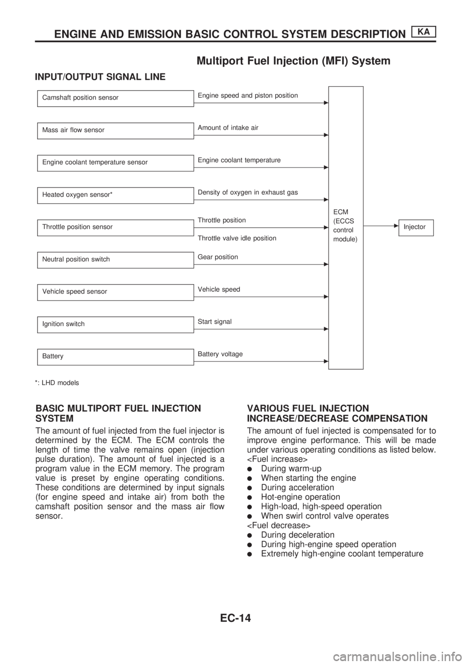
Multiport Fuel Injection (MFI) System
INPUT/OUTPUT SIGNAL LINE
Camshaft position sensorcEngine speed and piston position
ECM
(ECCS
control
module)
cInjector
Mass air flow sensorcAmount of intake air
Engine coolant temperature sensor
cEngine coolant temperature
Heated oxygen sensor*
cDensity of oxygen in exhaust gas
Throttle position sensor
cThrottle position
Throttle valve idle position
Neutral position switch
cGear position
Vehicle speed sensor
cVehicle speed
Ignition switch
cStart signal
Battery
cBattery voltage
*: LHD models
BASIC MULTIPORT FUEL INJECTION
SYSTEM
The amount of fuel injected from the fuel injector is
determined by the ECM. The ECM controls the
length of time the valve remains open (injection
pulse duration). The amount of fuel injected is a
program value in the ECM memory. The program
value is preset by engine operating conditions.
These conditions are determined by input signals
(for engine speed and intake air) from both the
camshaft position sensor and the mass air flow
sensor.
VARIOUS FUEL INJECTION
INCREASE/DECREASE COMPENSATION
The amount of fuel injected is compensated for to
improve engine performance. This will be made
under various operating conditions as listed below.
lDuring warm-up
lWhen starting the engine
lDuring acceleration
lHot-engine operation
lHigh-load, high-speed operation
lWhen swirl control valve operates
lDuring deceleration
lDuring high-engine speed operation
lExtremely high-engine coolant temperature
ENGINE AND EMISSION BASIC CONTROL SYSTEM DESCRIPTIONKA
EC-14
Page 169 of 1659
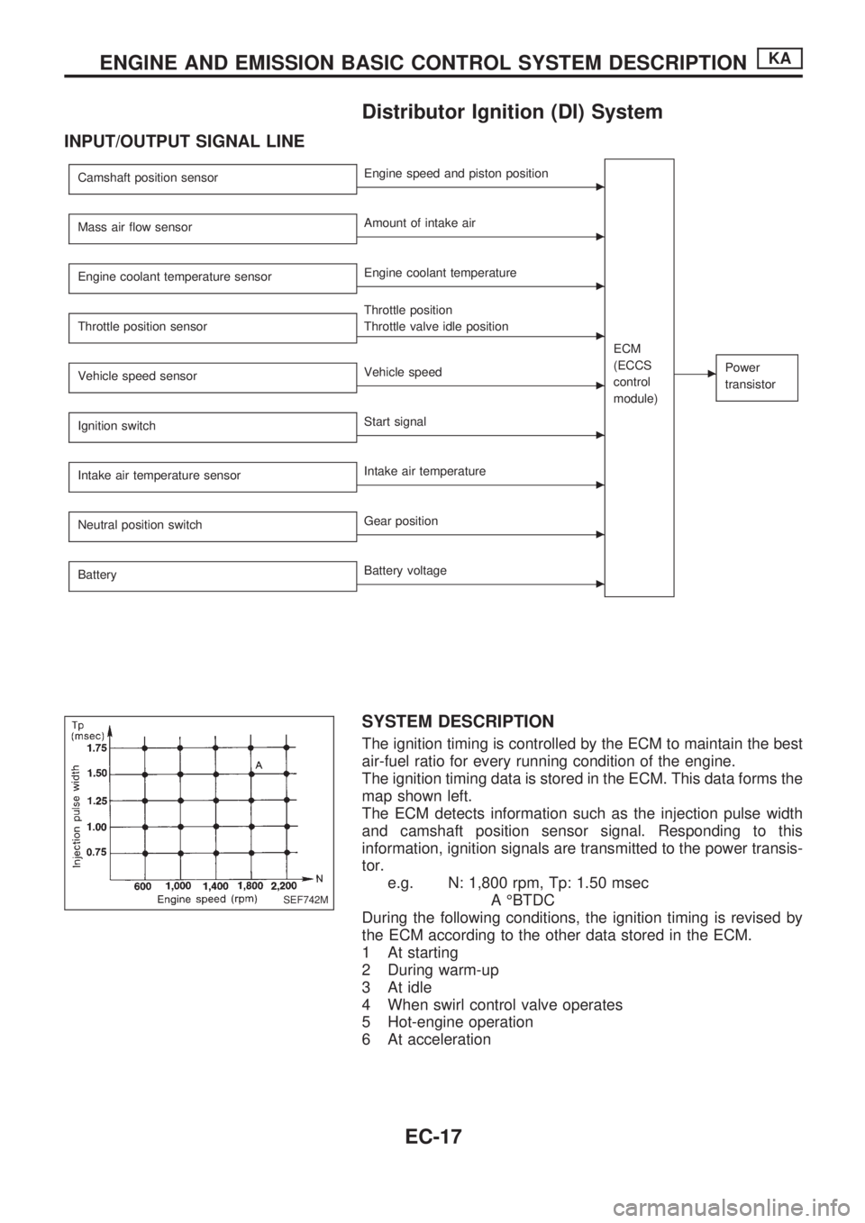
Distributor Ignition (DI) System
INPUT/OUTPUT SIGNAL LINE
Camshaft position sensorcEngine speed and piston position
ECM
(ECCS
control
module)
cPower
transistor
Mass air flow sensorcAmount of intake air
Engine coolant temperature sensor
cEngine coolant temperature
Throttle position sensor
c
Throttle position
Throttle valve idle position
Vehicle speed sensor
cVehicle speed
Ignition switch
cStart signal
Intake air temperature sensor
cIntake air temperature
Neutral position switch
cGear position
Battery
cBattery voltage
SYSTEM DESCRIPTION
The ignition timing is controlled by the ECM to maintain the best
air-fuel ratio for every running condition of the engine.
The ignition timing data is stored in the ECM. This data forms the
map shown left.
The ECM detects information such as the injection pulse width
and camshaft position sensor signal. Responding to this
information, ignition signals are transmitted to the power transis-
tor.
e.g. N: 1,800 rpm, Tp: 1.50 msec
A ÉBTDC
During the following conditions, the ignition timing is revised by
the ECM according to the other data stored in the ECM.
1 At starting
2 During warm-up
3 At idle
4 When swirl control valve operates
5 Hot-engine operation
6 At acceleration
SEF742M
ENGINE AND EMISSION BASIC CONTROL SYSTEM DESCRIPTIONKA
EC-17
Page 177 of 1659
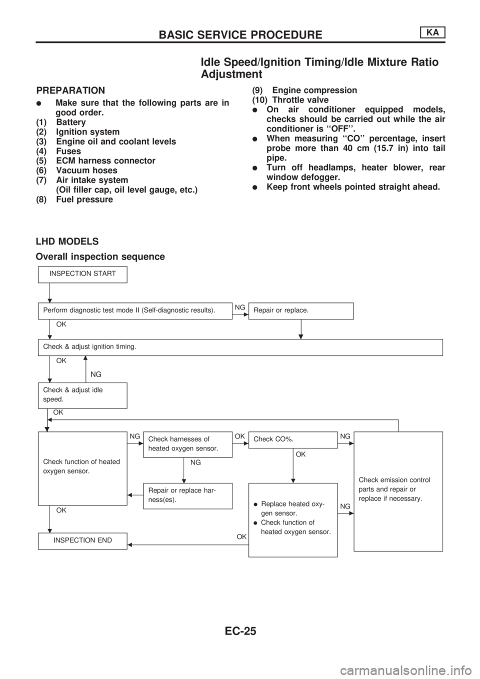
Idle Speed/Ignition Timing/Idle Mixture Ratio
Adjustment
PREPARATION
lMake sure that the following parts are in
good order.
(1) Battery
(2) Ignition system
(3) Engine oil and coolant levels
(4) Fuses
(5) ECM harness connector
(6) Vacuum hoses
(7) Air intake system
(Oil filler cap, oil level gauge, etc.)
(8) Fuel pressure(9) Engine compression
(10) Throttle valvelOn air conditioner equipped models,
checks should be carried out while the air
conditioner is ``OFF''.
lWhen measuring ``CO'' percentage, insert
probe more than 40 cm (15.7 in) into tail
pipe.
lTurn off headlamps, heater blower, rear
window defogger.
lKeep front wheels pointed straight ahead.
LHD MODELS
Overall inspection sequence
INSPECTION START
Perform diagnostic test mode II (Self-diagnostic results).
OK
cNG
Repair or replace.
.
Check & adjust ignition timing.
OKm
NG
Check & adjust idle
speed.
.
OKb
Check function of heated
oxygen sensor.
OK
cNG
Check harnesses of
heated oxygen sensor.
NG
cOK
Check CO%.
OK
.
cNG
Check emission control
parts and repair or
replace if necessary.
bRepair or replace har-
ness(es).
lReplace heated oxy-
gen sensor.
lCheck function of
heated oxygen sensor.
cNG
INSPECTION END
bOK
.
.
.
.
.
BASIC SERVICE PROCEDUREKA
EC-25
Page 181 of 1659
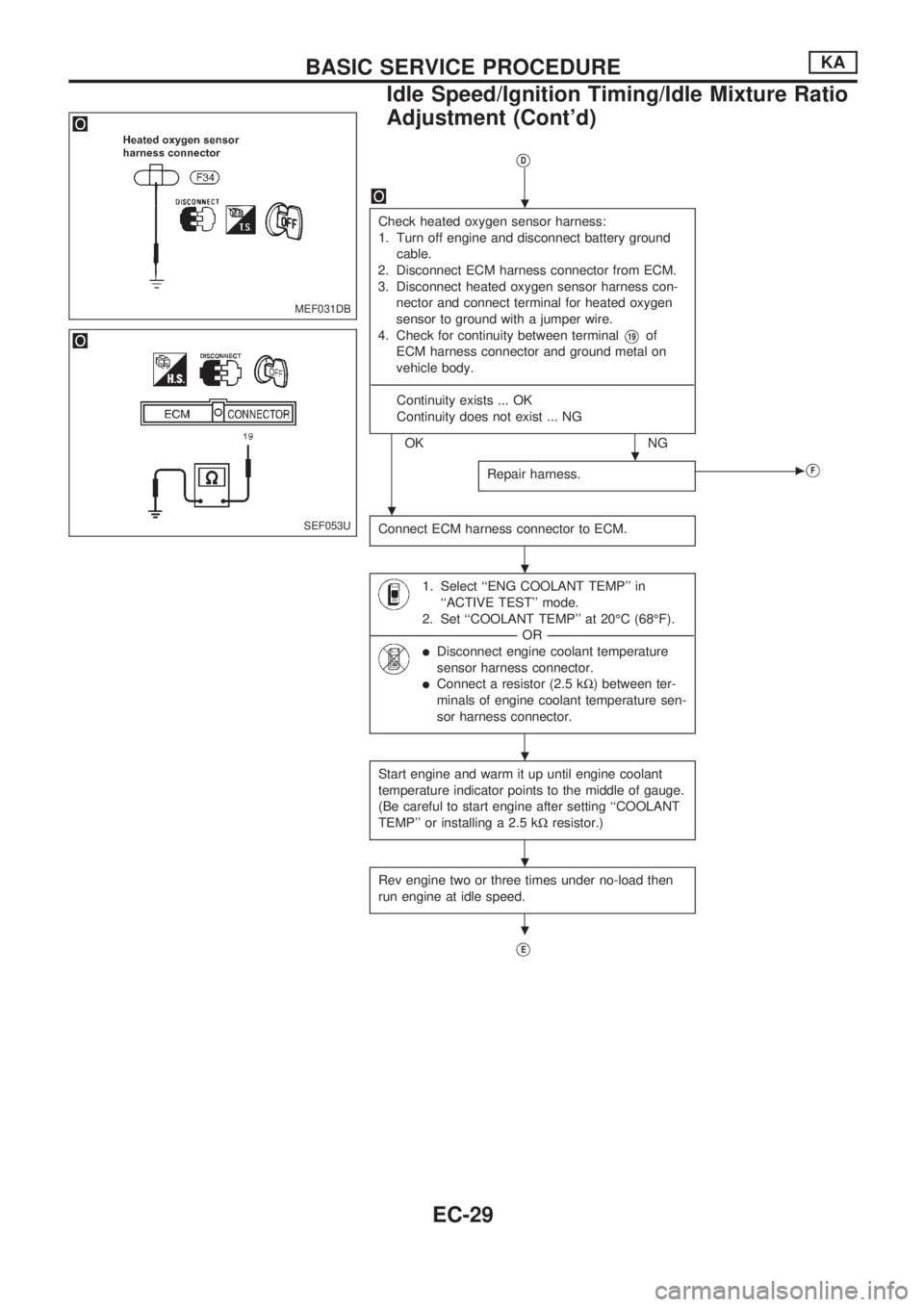
VD
Check heated oxygen sensor harness:
1. Turn off engine and disconnect battery ground
cable.
2. Disconnect ECM harness connector from ECM.
3. Disconnect heated oxygen sensor harness con-
nector and connect terminal for heated oxygen
sensor to ground with a jumper wire.
4. Check for continuity between terminal
V19of
ECM harness connector and ground metal on
vehicle body.
----------------------------------------------------------------------------------------------------------------------------------------------------------------------------------------------------------------------------------------------------------------------------------------------------------------------------------------------------------------------------
Continuity exists ... OK
Continuity does not exist ... NG
OK NG
Repair harness.
cVF
Connect ECM harness connector to ECM.
1. Select ``ENG COOLANT TEMP'' in
``ACTIVE TEST'' mode.
2. Set ``COOLANT TEMP'' at 20ÉC (68ÉF).
--------------------------------------------------------------------------------------------------------------------------------------------------------------------OR--------------------------------------------------------------------------------------------------------------------------------------------------------------------
lDisconnect engine coolant temperature
sensor harness connector.
lConnect a resistor (2.5 kW) between ter-
minals of engine coolant temperature sen-
sor harness connector.
Start engine and warm it up until engine coolant
temperature indicator points to the middle of gauge.
(Be careful to start engine after setting ``COOLANT
TEMP'' or installing a 2.5 kWresistor.)
Rev engine two or three times under no-load then
run engine at idle speed.
VE
MEF031DB
SEF053U
.
.
.
.
.
.
.
BASIC SERVICE PROCEDUREKA
Idle Speed/Ignition Timing/Idle Mixture Ratio
Adjustment (Cont'd)
EC-29
Page 188 of 1659
Introduction
The ECM (ECCS control module) has an on board diagnostic system, which detects malfunctions related to
engine sensors or actuators. Self-diagnosis items are listed in ``DIAGNOSTIC TROUBLE CODE INDEX'',
EC-1.
The malfunction indicator lamp (MIL) on the instrument panel lights up when a malfunction is detected, or
when the ECM enters fail-safe mode (Refer to EC-61).
Diagnostic Trouble Code (DTC)
HOW TO CONFIRM MALFUNCTION ITEMS
Malfunction items can be confirmed by the following methods.
1. The number of blinks of the malfunction indicator lamp in the Diagnostic Test Mode II (Self- Diag-
nostic Results) indicates the DTC. Examples: 11, 21 etc.
2. CONSULT displays the malfunctioning component or system in ``SELF DIAGNOSTIC RESULTS''
mode.
lOutput of a DTC indicates a malfunction. However, Mode II does not indicate whether the mal-
function is still occurring or has occurred in the past and has returned to normal.
CONSULT can identify malfunction status as shown below. Therefore, using CONSULT (if avail-
able) is recommended.
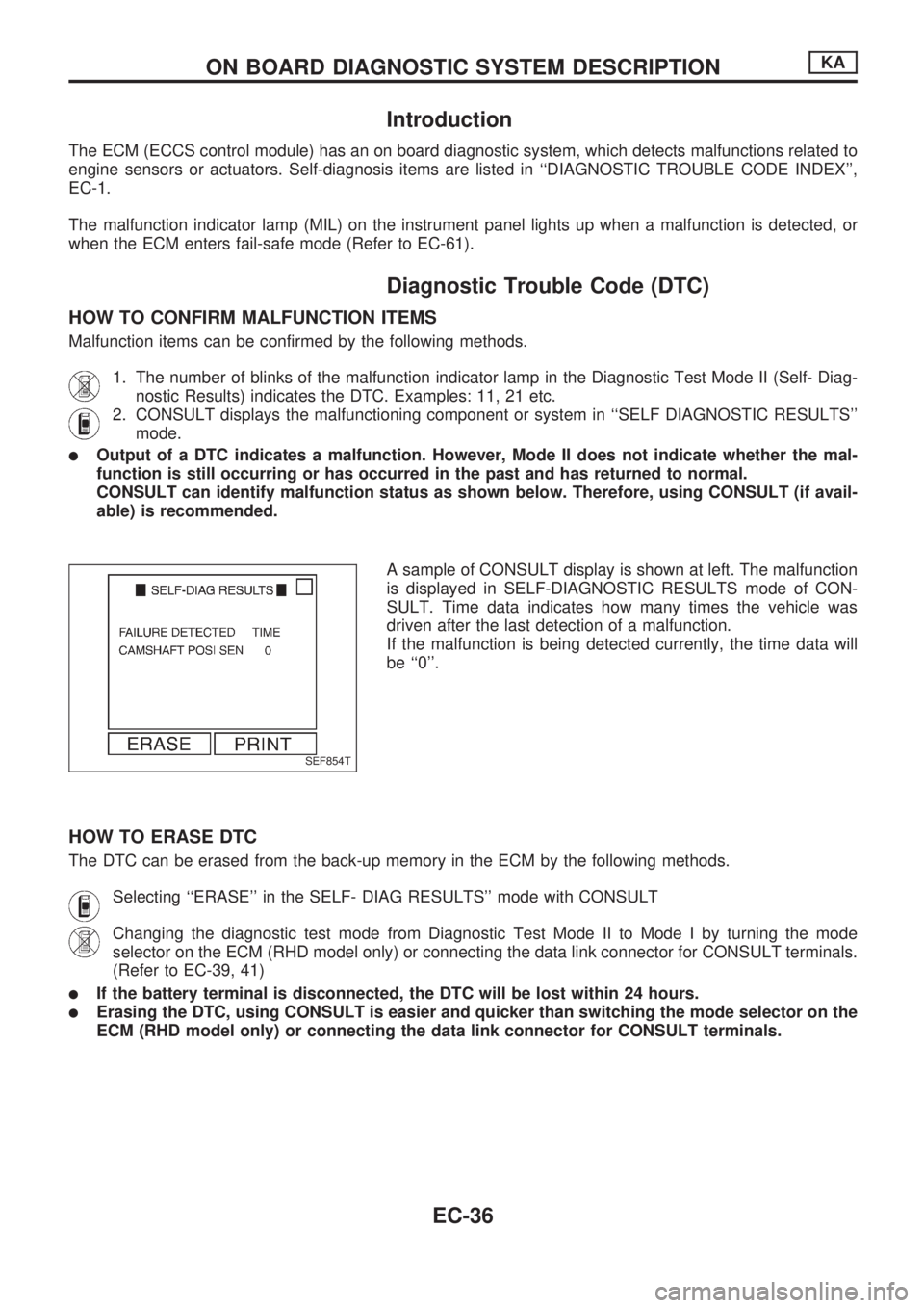
A sample of CONSULT display is shown at left. The malfunction
is displayed in SELF-DIAGNOSTIC RESULTS mode of CON-
SULT. Time data indicates how many times the vehicle was
driven after the last detection of a malfunction.
If the malfunction is being detected currently, the time data will
be ``0''.
HOW TO ERASE DTC
The DTC can be erased from the back-up memory in the ECM by the following methods.
Selecting ``ERASE'' in the SELF- DIAG RESULTS'' mode with CONSULT
Changing the diagnostic test mode from Diagnostic Test Mode II to Mode I by turning the mode
selector on the ECM (RHD model only) or connecting the data link connector for CONSULT terminals.
(Refer to EC-39, 41)
lIf the battery terminal is disconnected, the DTC will be lost within 24 hours.
lErasing the DTC, using CONSULT is easier and quicker than switching the mode selector on the
ECM (RHD model only) or connecting the data link connector for CONSULT terminals.
SEF854T
ON BOARD DIAGNOSTIC SYSTEM DESCRIPTIONKA
EC-36
Page 195 of 1659
DIAGNOSTIC TEST MODE IÐBULB CHECK
In this mode, the MALFUNCTION INDICATOR LAMP on the instrument panel should stay ON. If it remains
OFF, check the bulb. (See the WARNING LAMPS AND CHIME in the EL section. Or see EC-173, 174.)
DIAGNOSTIC TEST MODE IÐMALFUNCTION WARNING
MALFUNCTION
INDICATOR LAMPCondition
ON When the malfunction is detected (Refer to EC-1.) or the ECM's CPU is malfunctioning.
OFF No malfunction
lThese Diagnostic Trouble Code Numbers are clarified in Diagnostic Test Mode II (SELF-DIAGNOSTIC
RESULTS).
DIAGNOSTIC TEST MODE IIÐSELF-DIAGNOSTIC RESULTS
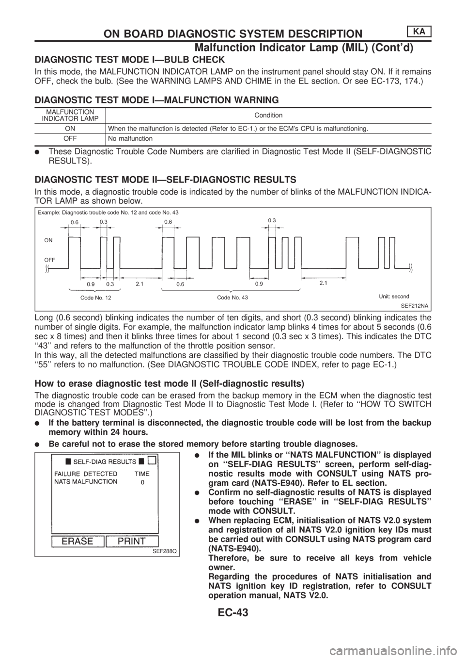
In this mode, a diagnostic trouble code is indicated by the number of blinks of the MALFUNCTION INDICA-
TOR LAMP as shown below.
Long (0.6 second) blinking indicates the number of ten digits, and short (0.3 second) blinking indicates the
number of single digits. For example, the malfunction indicator lamp blinks 4 times for about 5 seconds (0.6
sec x 8 times) and then it blinks three times for about 1 second (0.3 sec x 3 times). This indicates the DTC
``43'' and refers to the malfunction of the throttle position sensor.
In this way, all the detected malfunctions are classified by their diagnostic trouble code numbers. The DTC
``55'' refers to no malfunction. (See DIAGNOSTIC TROUBLE CODE INDEX, refer to page EC-1.)
How to erase diagnostic test mode II (Self-diagnostic results)
The diagnostic trouble code can be erased from the backup memory in the ECM when the diagnostic test
mode is changed from Diagnostic Test Mode II to Diagnostic Test Mode I. (Refer to ``HOW TO SWITCH
DIAGNOSTIC TEST MODES''.)
lIf the battery terminal is disconnected, the diagnostic trouble code will be lost from the backup
memory within 24 hours.
lBe careful not to erase the stored memory before starting trouble diagnoses.
lIf the MIL blinks or ``NATS MALFUNCTION'' is displayed
on ``SELF-DIAG RESULTS'' screen, perform self-diag-
nostic results mode with CONSULT using NATS pro-
gram card (NATS-E940). Refer to EL section.
lConfirm no self-diagnostic results of NATS is displayed
before touching ``ERASE'' in ``SELF-DIAG RESULTS''
mode with CONSULT.
lWhen replacing ECM, initialisation of NATS V2.0 system
and registration of all NATS V2.0 ignition key IDs must
be carried out with CONSULT using NATS program card
(NATS-E940).
Therefore, be sure to receive all keys from vehicle
owner.
Regarding the procedures of NATS initialisation and
NATS ignition key ID registration, refer to CONSULT
operation manual, NATS V2.0.
SEF212NA
SEF288Q
ON BOARD DIAGNOSTIC SYSTEM DESCRIPTIONKA
Malfunction Indicator Lamp (MIL) (Cont'd)
EC-43