battery NISSAN PICK-UP 1998 Workshop Manual
[x] Cancel search | Manufacturer: NISSAN, Model Year: 1998, Model line: PICK-UP, Model: NISSAN PICK-UP 1998Pages: 1659, PDF Size: 53.39 MB
Page 322 of 1659
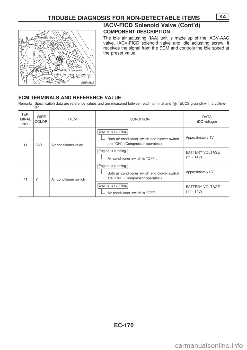
COMPONENT DESCRIPTION
The idle air adjusting (IAA) unit is made up of the IACV-AAC
valve, IACV-FICD solenoid valve and idle adjusting screw. It
receives the signal from the ECM and controls the idle speed at
the preset value.
ECM TERMINALS AND REFERENCE VALUE
Remarks: Specification data are reference values and are measured between each terminal andV39(ECCS ground) with a voltme-
ter.
TER-
MINAL
NO.WIRE
COLORITEM CONDITIONDATA
(DC voltage)
11 G/R Air conditioner relayEngine is running.
Both air conditioner switch and blower switch
are ``ON''. (Compressor operates.)Approximately 1V
Engine is running.
Air conditioner switch is ``OFF''.BATTERY VOLTAGE
(11 - 14V)
41 Y Air conditioner switchEngine is running.
Both air conditioner switch and blower switch
are ``ON''. (Compressor operates.)Approximately 0V
Engine is running.
Air conditioner switch is ``OFF''.BATTERY VOLTAGE
(11 - 14V)
SEF158U
TROUBLE DIAGNOSIS FOR NON-DETECTABLE ITEMSKA
IACV-FICD Solenoid Valve (Cont'd)
EC-170
Page 323 of 1659

DIAGNOSTIC PROCEDURE
INSPECTION START
CHECK OVERALL FUNCTION.
1. Start engine and warm it up suffi-
ciently.
2. Check idle speed.
800 50 rpm
If NG, adjust idle speed.
3. Turn air conditioner switch and blower
fan switch ``ON''.
4. Recheck idle speed.
900 rpm or more
NG
cOK
INSPECTION END
Check if air conditioner compressor func-
tions normally.
OK
cNG
Refer to HA section.
CHECK POWER SUPPLY.
1. Stop engine.
2. Disconnect IACV-FICD solenoid valve
harness connector.
3. Restart engine and turn air conditioner
switch and blower fan switch ``ON''.
4. Check voltage between terminal
V4
and ground with CONSULT or tester.
Voltage: Battery voltage
OK
cNG
Check the following.
lHarness connectors,
E101,M5
lHarness for open or
short between IACV-
FICD solenoid valve and
air conditioner relay
If NG, repair harness or
connectors.
CHECK GROUND CIRCUIT.
1. Turn ignition switch ``OFF''.
2. Check harness continuity between ter-
minal
V2and body ground.
Continuity should exist.
If OK, check harness for short to
ground and short to power.
OK
cNG
Repair open circuit, short
to ground or short to
power in harness or con-
nectors.
CHECK COMPONENT
(IACV-FICD solenoid valve).
Refer to ``COMPONENT INSPECTION''
on next page.
OK
cNG
Replace IACV-FICD sole-
noid valve.
VA
(Go to next page.)
MEF634E
SEF117U
SEF118U
.
.
.
.
.
.
TROUBLE DIAGNOSIS FOR NON-DETECTABLE ITEMSKA
IACV-FICD Solenoid Valve (Cont'd)
EC-171
Page 357 of 1659
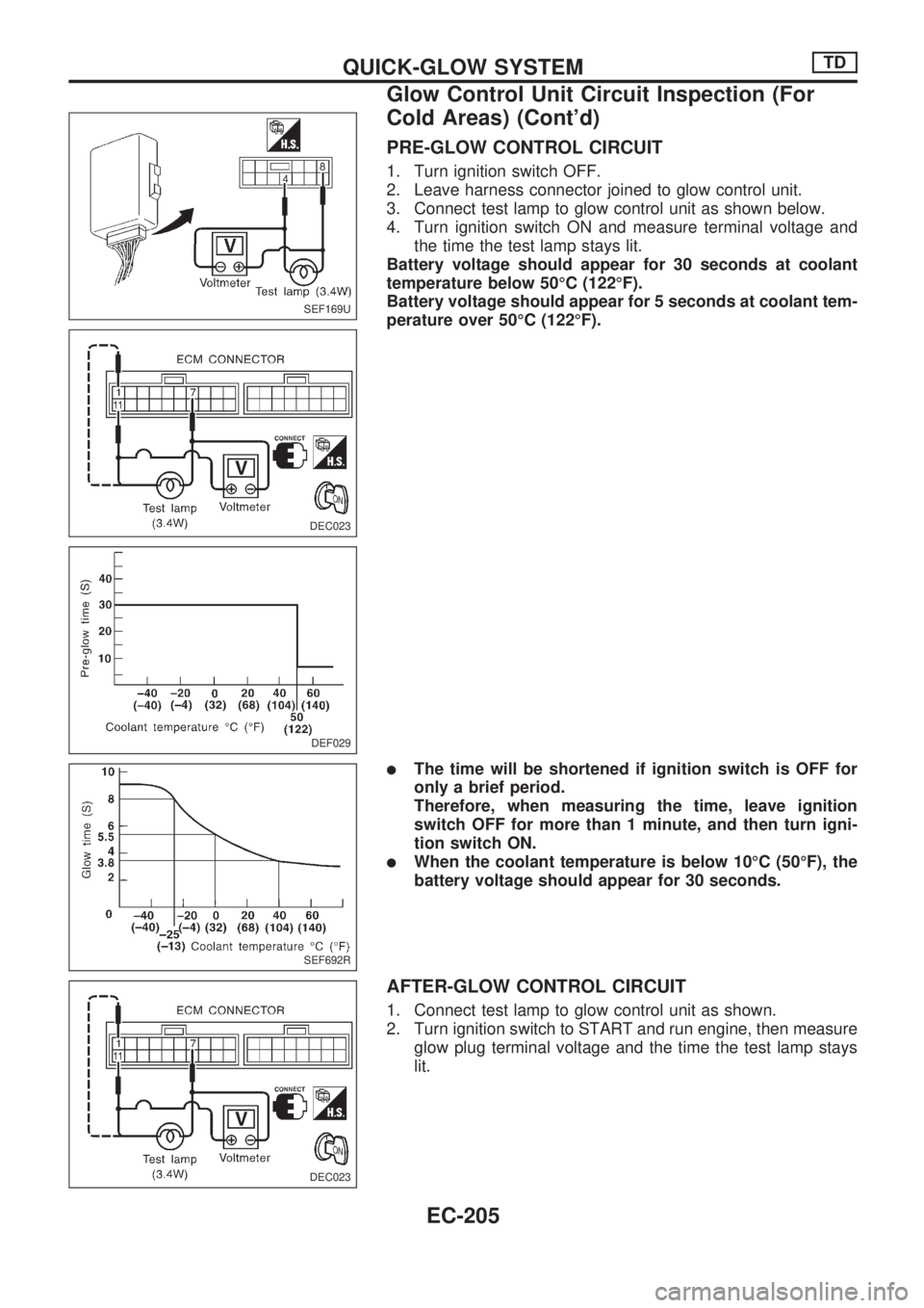
PRE-GLOW CONTROL CIRCUIT
1. Turn ignition switch OFF.
2. Leave harness connector joined to glow control unit.
3. Connect test lamp to glow control unit as shown below.
4. Turn ignition switch ON and measure terminal voltage and
the time the test lamp stays lit.
Battery voltage should appear for 30 seconds at coolant
temperature below 50ÉC (122ÉF).
Battery voltage should appear for 5 seconds at coolant tem-
perature over 50ÉC (122ÉF).
lThe time will be shortened if ignition switch is OFF for
only a brief period.
Therefore, when measuring the time, leave ignition
switch OFF for more than 1 minute, and then turn igni-
tion switch ON.
lWhen the coolant temperature is below 10ÉC (50ÉF), the
battery voltage should appear for 30 seconds.
AFTER-GLOW CONTROL CIRCUIT
1. Connect test lamp to glow control unit as shown.
2. Turn ignition switch to START and run engine, then measure
glow plug terminal voltage and the time the test lamp stays
lit.
SEF169U
DEC023
DEF029
SEF692R
DEC023
QUICK-GLOW SYSTEMTD
Glow Control Unit Circuit Inspection (For
Cold Areas) (Cont'd)
EC-205
Page 358 of 1659
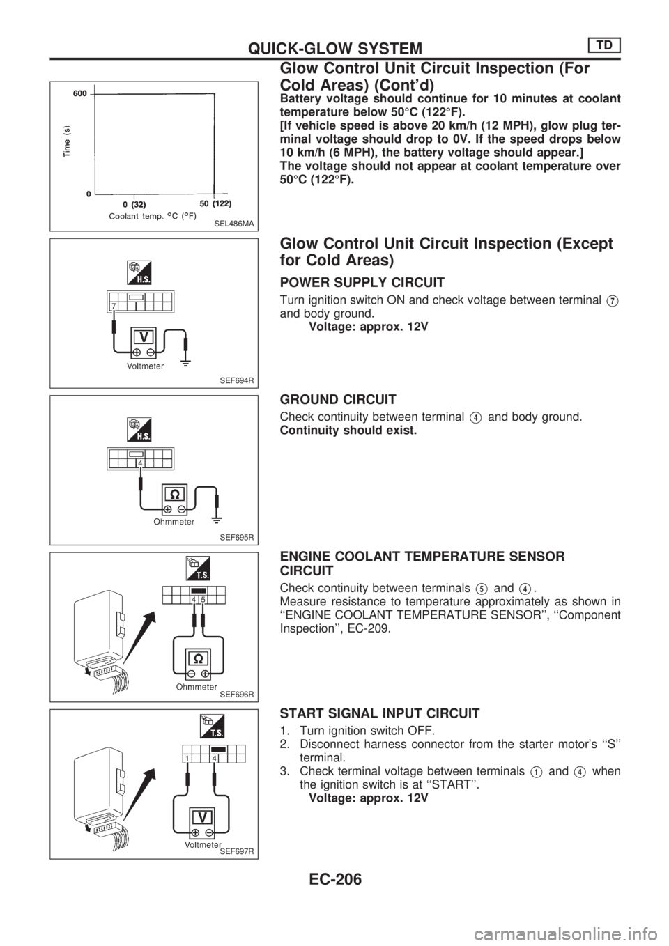
Battery voltage should continue for 10 minutes at coolant
temperature below 50ÉC (122ÉF).
[If vehicle speed is above 20 km/h (12 MPH), glow plug ter-
minal voltage should drop to 0V. If the speed drops below
10 km/h (6 MPH), the battery voltage should appear.]
The voltage should not appear at coolant temperature over
50ÉC (122ÉF).
Glow Control Unit Circuit Inspection (Except
for Cold Areas)
POWER SUPPLY CIRCUIT
Turn ignition switch ON and check voltage between terminalV7
and body ground.
Voltage: approx. 12V
GROUND CIRCUIT
Check continuity between terminalV4and body ground.
Continuity should exist.
ENGINE COOLANT TEMPERATURE SENSOR
CIRCUIT
Check continuity between terminalsV5andV4.
Measure resistance to temperature approximately as shown in
``ENGINE COOLANT TEMPERATURE SENSOR'', ``Component
Inspection'', EC-209.
START SIGNAL INPUT CIRCUIT
1. Turn ignition switch OFF.
2. Disconnect harness connector from the starter motor's ``S''
terminal.
3. Check terminal voltage between terminals
V1andV4when
the ignition switch is at ``START''.
Voltage: approx. 12V
SEL486MA
SEF694R
SEF695R
SEF696R
SEF697R
QUICK-GLOW SYSTEMTD
Glow Control Unit Circuit Inspection (For
Cold Areas) (Cont'd)
EC-206
Page 359 of 1659
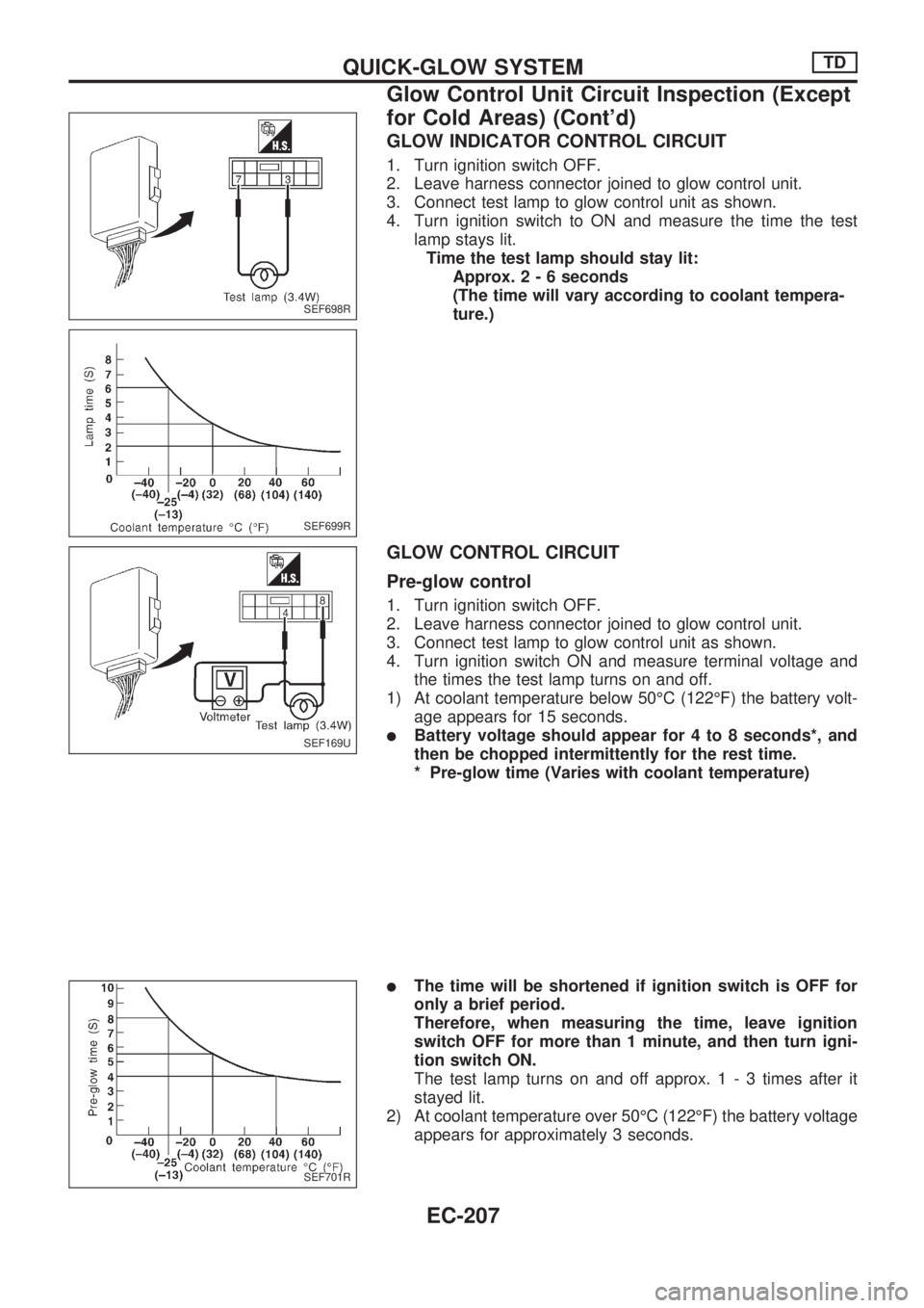
GLOW INDICATOR CONTROL CIRCUIT
1. Turn ignition switch OFF.
2. Leave harness connector joined to glow control unit.
3. Connect test lamp to glow control unit as shown.
4. Turn ignition switch to ON and measure the time the test
lamp stays lit.
Time the test lamp should stay lit:
Approx.2-6seconds
(The time will vary according to coolant tempera-
ture.)
GLOW CONTROL CIRCUIT
Pre-glow control
1. Turn ignition switch OFF.
2. Leave harness connector joined to glow control unit.
3. Connect test lamp to glow control unit as shown.
4. Turn ignition switch ON and measure terminal voltage and
the times the test lamp turns on and off.
1) At coolant temperature below 50ÉC (122ÉF) the battery volt-
age appears for 15 seconds.
lBattery voltage should appear for 4 to 8 seconds*, and
then be chopped intermittently for the rest time.
* Pre-glow time (Varies with coolant temperature)
lThe time will be shortened if ignition switch is OFF for
only a brief period.
Therefore, when measuring the time, leave ignition
switch OFF for more than 1 minute, and then turn igni-
tion switch ON.
The test lamp turns on and off approx. 1 - 3 times after it
stayed lit.
2) At coolant temperature over 50ÉC (122ÉF) the battery voltage
appears for approximately 3 seconds.
SEF698R
SEF699R
SEF169U
SEF701R
QUICK-GLOW SYSTEMTD
Glow Control Unit Circuit Inspection (Except
for Cold Areas) (Cont'd)
EC-207
Page 360 of 1659
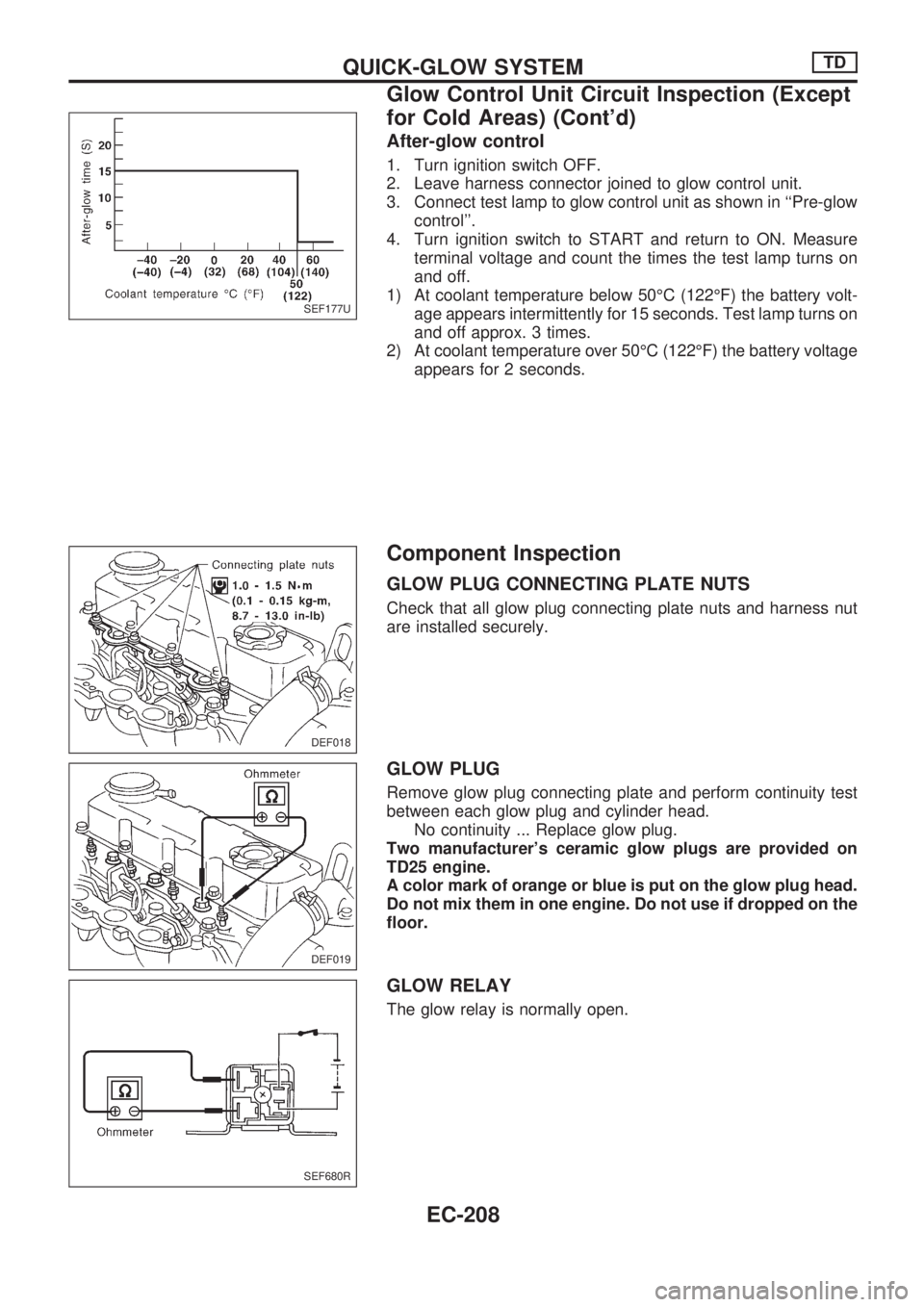
After-glow control
1. Turn ignition switch OFF.
2. Leave harness connector joined to glow control unit.
3. Connect test lamp to glow control unit as shown in ``Pre-glow
control''.
4. Turn ignition switch to START and return to ON. Measure
terminal voltage and count the times the test lamp turns on
and off.
1) At coolant temperature below 50ÉC (122ÉF) the battery volt-
age appears intermittently for 15 seconds. Test lamp turns on
and off approx. 3 times.
2) At coolant temperature over 50ÉC (122ÉF) the battery voltage
appears for 2 seconds.
Component Inspection
GLOW PLUG CONNECTING PLATE NUTS
Check that all glow plug connecting plate nuts and harness nut
are installed securely.
GLOW PLUG
Remove glow plug connecting plate and perform continuity test
between each glow plug and cylinder head.
No continuity ... Replace glow plug.
Two manufacturer's ceramic glow plugs are provided on
TD25 engine.
A color mark of orange or blue is put on the glow plug head.
Do not mix them in one engine. Do not use if dropped on the
floor.
GLOW RELAY
The glow relay is normally open.
SEF177U
DEF018
DEF019
SEF680R
QUICK-GLOW SYSTEMTD
Glow Control Unit Circuit Inspection (Except
for Cold Areas) (Cont'd)
EC-208
Page 369 of 1659

System Inspection
OVERALL FUNCTION
1. Start engine and warm it up sufficiently.
2. Make sure that EGR valve diaphragm and throttle chamber
control valve rod movement (Use your finger to confirm EGR
valve diaphragm movement) under the following conditions.
At idle:
Diaphragm and rod do not move.
Revving engine from idle to between 1,000 and 2,800
rpm:
Diaphragm and rod move.
Keeping engine speed between 2,900 and 3,200 rpm:
Diaphragm and rod stay in open position.
POWER SUPPLY CIRCUIT
1. Turn ignition switch OFF.
2. Disconnect EGRC-solenoid valve A and B harness connec-
tor.
3. Turn ignition switch ON.
4. Check voltage between terminal
V2and ground.
Voltage: Battery voltage
OUTPUT SIGNAL CIRCUIT
1. Turn ignition switch OFF.
2. Disconnect ECM harness connector.
3. Check harness continuity between terminals.
Continuity should exist.
If OK, check harness for short.
EGRC-solenoid valve A:
ECM terminal
V36and terminalV1orV11
EGRC-solenoid valve B:
ECM terminal
V34and terminalV1orV11
DEC027
DEC028
DEC029
SEF674P
DEC041
EGR SYSTEMTD
EC-217
Page 376 of 1659
Inspection
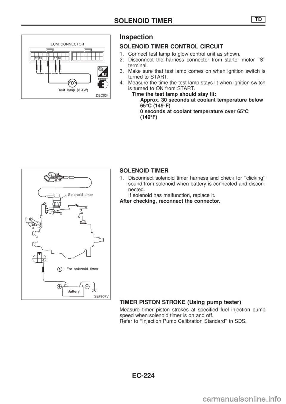
SOLENOID TIMER CONTROL CIRCUIT
1. Connect test lamp to glow control unit as shown.
2. Disconnect the harness connector from starter motor ``S''
terminal.
3. Make sure that test lamp comes on when ignition switch is
turned to START.
4. Measure the time the test lamp stays lit when ignition switch
is turned to ON from START.
Time the test lamp should stay lit:
Approx. 30 seconds at coolant temperature below
65ÉC (149ÉF)
0 seconds at coolant temperature over 65ÉC
(149ÉF)
SOLENOID TIMER
1. Disconnect solenoid timer harness and check for ``clicking''
sound from solenoid when battery is connected and discon-
nected.
If solenoid has malfunction, replace it.
After checking, reconnect the connector.
TIMER PISTON STROKE (Using pump tester)
Measure timer piston strokes at specified fuel injection pump
speed when solenoid timer is on and off.
Refer to ``Injection Pump Calibration Standard'' in SDS.
DEC034
.
SEF907V
SOLENOID TIMERTD
EC-224
Page 383 of 1659
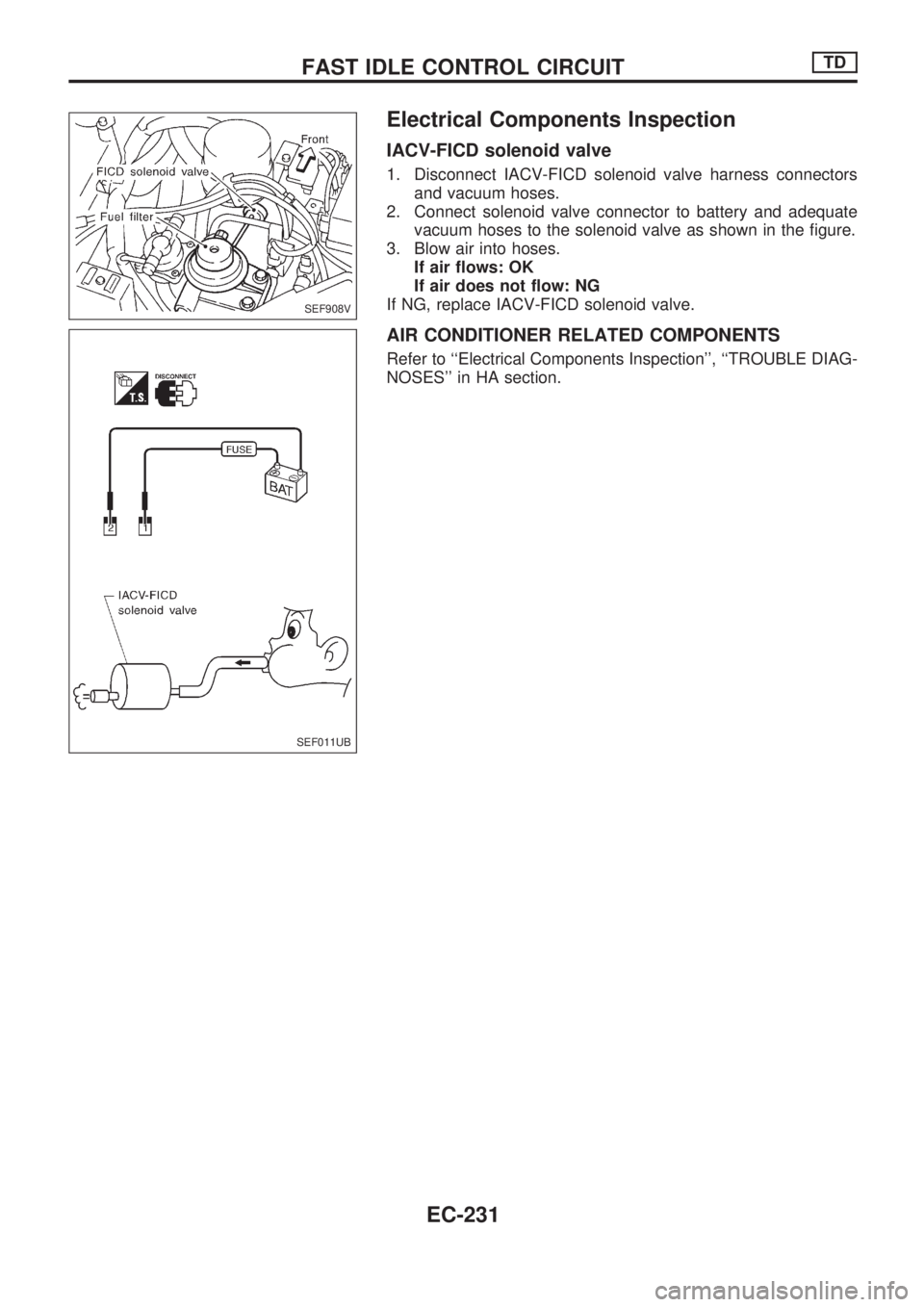
Electrical Components Inspection
IACV-FICD solenoid valve
1. Disconnect IACV-FICD solenoid valve harness connectors
and vacuum hoses.
2. Connect solenoid valve connector to battery and adequate
vacuum hoses to the solenoid valve as shown in the figure.
3. Blow air into hoses.
If air flows: OK
If air does not flow: NG
If NG, replace IACV-FICD solenoid valve.
AIR CONDITIONER RELATED COMPONENTS
Refer to ``Electrical Components Inspection'', ``TROUBLE DIAG-
NOSES'' in HA section.
SEF908V
SEF011UB
FAST IDLE CONTROL CIRCUITTD
EC-231
Page 384 of 1659
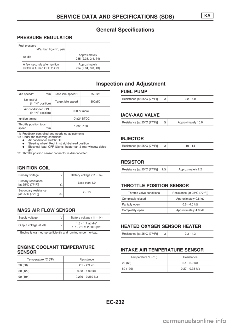
General Specifications
PRESSURE REGULATOR
Fuel pressure
kPa (bar, kg/cm2, psi)
At idleApproximately
235 (2.35, 2.4, 34)
A few seconds after ignition
switch is turned OFF to ONApproximately
294 (2.94, 3.0, 43)
Inspection and Adjustment
Idle speed*1 rpm Base idle speed*3 750 25
No-load*2
(in ``N'' position)Target idle speed 800 50
Air conditioner: ON
(in ``N'' position)900 or more
Ignition timing 10É 2É BTDC
Throttle position touch
speed rpm1,000 150
*1: Feedback controlled and needs no adjustments
*2: Under the following conditions:
lAir conditioner switch: OFFlSteering wheel: Kept in straight-ahead positionlElectrical load: OFF (Lights, heater fan & rear window defog-
ger)
*3: Throttle position sensor connector is disconnected.
IGNITION COIL
Primary voltage V Battery voltage (11 - 14)
Primary resistance
[at 25ÉC (77ÉF)]WLess than 1.0
Secondary resistance
[at 25ÉC (77ÉF)] kW7-13
MASS AIR FLOW SENSOR
Supply voltage V Battery voltage (11 - 14)
Output voltage at idle V1.3 - 1.7 at idle*
1.7 - 2.1 at 2,500 rpm*
*: Engine is warmed up sufficiently and running under no-load.
ENGINE COOLANT TEMPERATURE
SENSOR
Temperature ÉC (ÉF) Resistance
20 (68) 2.1 - 2.9 kW
50 (122) 0.68 - 1.00 kW
90 (194) 0.236 - 0.260 kW
FUEL PUMP
Resistance [at 25ÉC (77ÉF)]W0.2 - 5.0
IACV-AAC VALVE
Resistance [at 25ÉC (77ÉF)]WApproximately 10.0
INJECTOR
Resistance [at 25ÉC (77ÉF)]W10-14
RESISTOR
Resistance [at 25ÉC (77ÉF)] kWApproximately 2.2
THROTTLE POSITION SENSOR
Throttle valve conditions Resistance [at 25ÉC (77ÉF)]
Completely closed Approximately 0.6 kW
Partially open 0.6 - 4.0 kW
Completely open Approximately 4.0 kW
HEATED OXYGEN SENSOR HEATER
Resistance [at 25ÉC (77ÉF)]W2.3 - 4.3
INTAKE AIR TEMPERATURE SENSOR
Temperature ÉC (ÉF) Resistance
20 (68) 2.1 - 2.9 kW
80 (176) 0.27 - 0.38 kW
SERVICE DATA AND SPECIFICATIONS (SDS)KA
EC-232