brake light NISSAN PICK-UP 1998 Repair Manual
[x] Cancel search | Manufacturer: NISSAN, Model Year: 1998, Model line: PICK-UP, Model: NISSAN PICK-UP 1998Pages: 1659, PDF Size: 53.39 MB
Page 18 of 1659
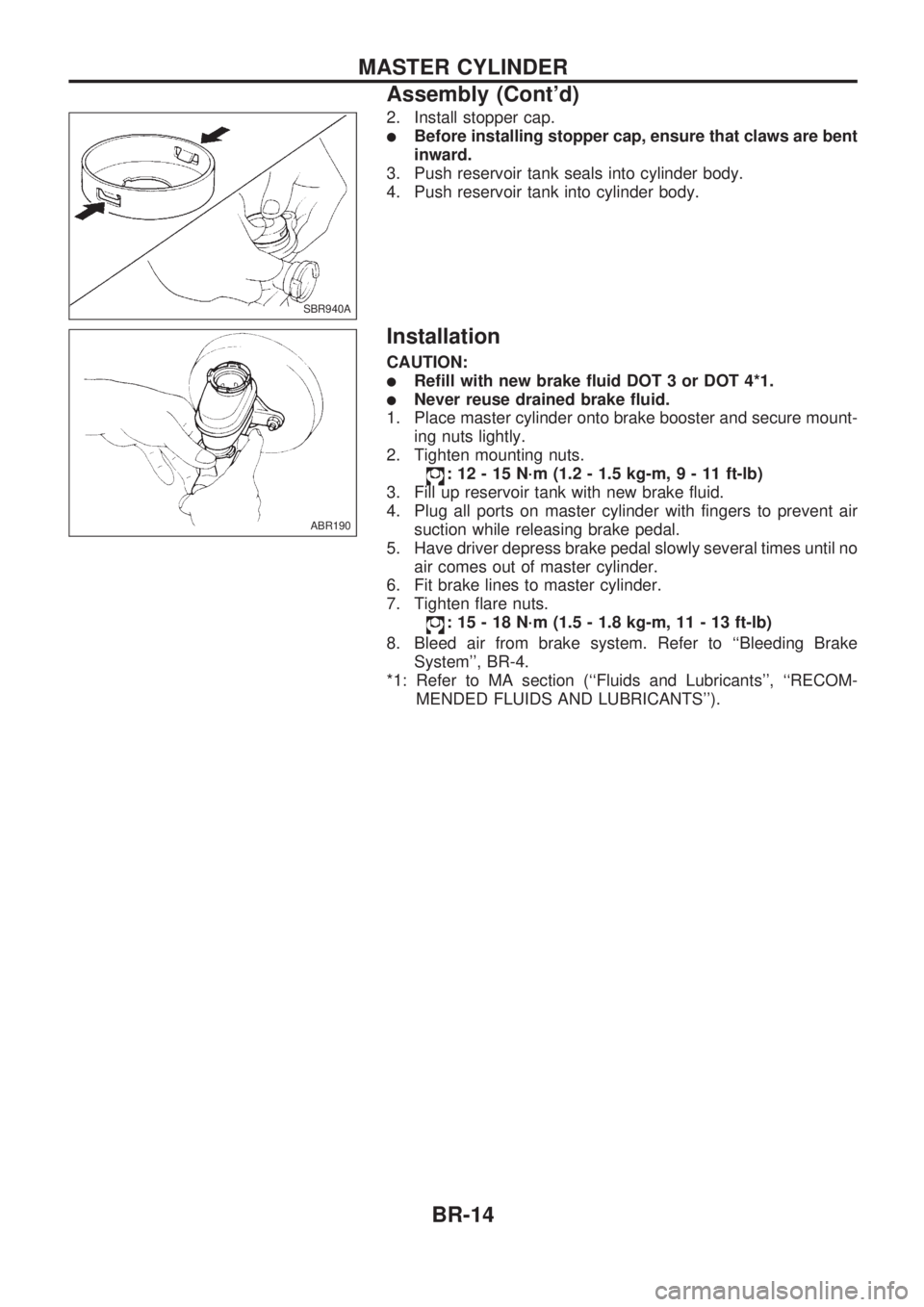
2. Install stopper cap.
lBefore installing stopper cap, ensure that claws are bent
inward.
3. Push reservoir tank seals into cylinder body.
4. Push reservoir tank into cylinder body.
Installation
CAUTION:
lRefill with new brake fluid DOT 3 or DOT 4*1.
lNever reuse drained brake fluid.
1. Place master cylinder onto brake booster and secure mount-
ing nuts lightly.
2. Tighten mounting nuts.
: 12 - 15 N´m (1.2 - 1.5 kg-m,9-11ft-lb)
3. Fill up reservoir tank with new brake fluid.
4. Plug all ports on master cylinder with fingers to prevent air
suction while releasing brake pedal.
5. Have driver depress brake pedal slowly several times until no
air comes out of master cylinder.
6. Fit brake lines to master cylinder.
7. Tighten flare nuts.
: 15 - 18 N´m (1.5 - 1.8 kg-m, 11 - 13 ft-lb)
8. Bleed air from brake system. Refer to ``Bleeding Brake
System'', BR-4.
*1: Refer to MA section (``Fluids and Lubricants'', ``RECOM-
MENDED FLUIDS AND LUBRICANTS'').
SBR940A
ABR190
MASTER CYLINDER
Assembly (Cont'd)
BR-14
Page 19 of 1659
On-vehicle Service
OPERATING CHECK
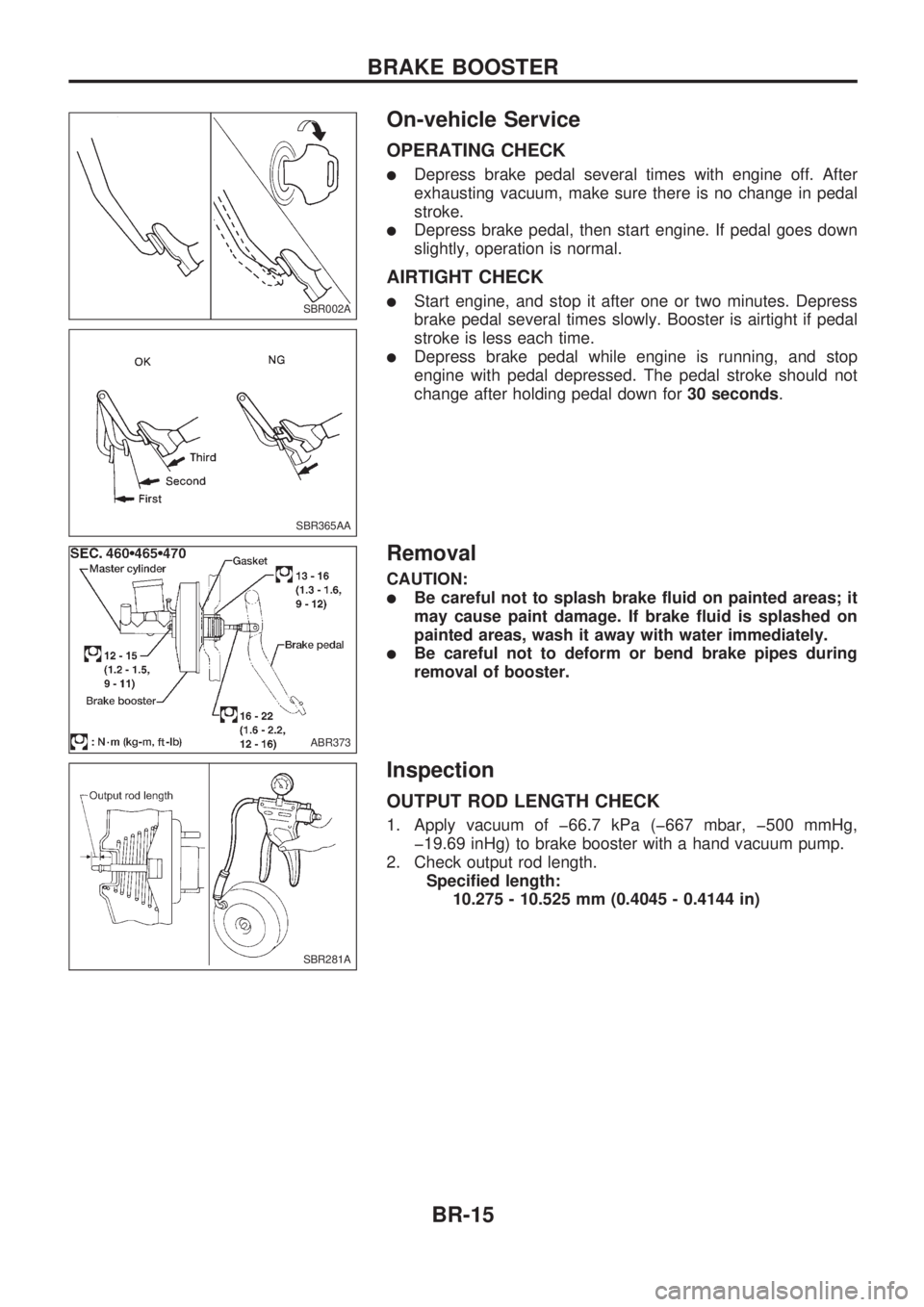
lDepress brake pedal several times with engine off. After
exhausting vacuum, make sure there is no change in pedal
stroke.
lDepress brake pedal, then start engine. If pedal goes down
slightly, operation is normal.
AIRTIGHT CHECK
lStart engine, and stop it after one or two minutes. Depress
brake pedal several times slowly. Booster is airtight if pedal
stroke is less each time.
lDepress brake pedal while engine is running, and stop
engine with pedal depressed. The pedal stroke should not
change after holding pedal down for30 seconds.
Removal
CAUTION:
lBe careful not to splash brake fluid on painted areas; it
may cause paint damage. If brake fluid is splashed on
painted areas, wash it away with water immediately.
lBe careful not to deform or bend brake pipes during
removal of booster.
Inspection
OUTPUT ROD LENGTH CHECK
1. Apply vacuum of þ66.7 kPa (þ667 mbar, þ500 mmHg,
þ19.69 inHg) to brake booster with a hand vacuum pump.
2. Check output rod length.
Specified length:
10.275 - 10.525 mm (0.4045 - 0.4144 in)
SBR002A
SBR365AA
ABR373
SBR281A
BRAKE BOOSTER
BR-15
Page 20 of 1659
Installation
CAUTION:
lBe careful not to deform or bend brake pipes during
installation of booster.
lReplace clevis pin if damaged.
lRefill with new brake fluid DOT 3 or DOT 4*1.
lNever reuse drained brake fluid.
lTake care not to damage brake booster mounting bolt
thread when installing. Due to the narrow angle of
installation, the threads can be damaged by the dash
panel.
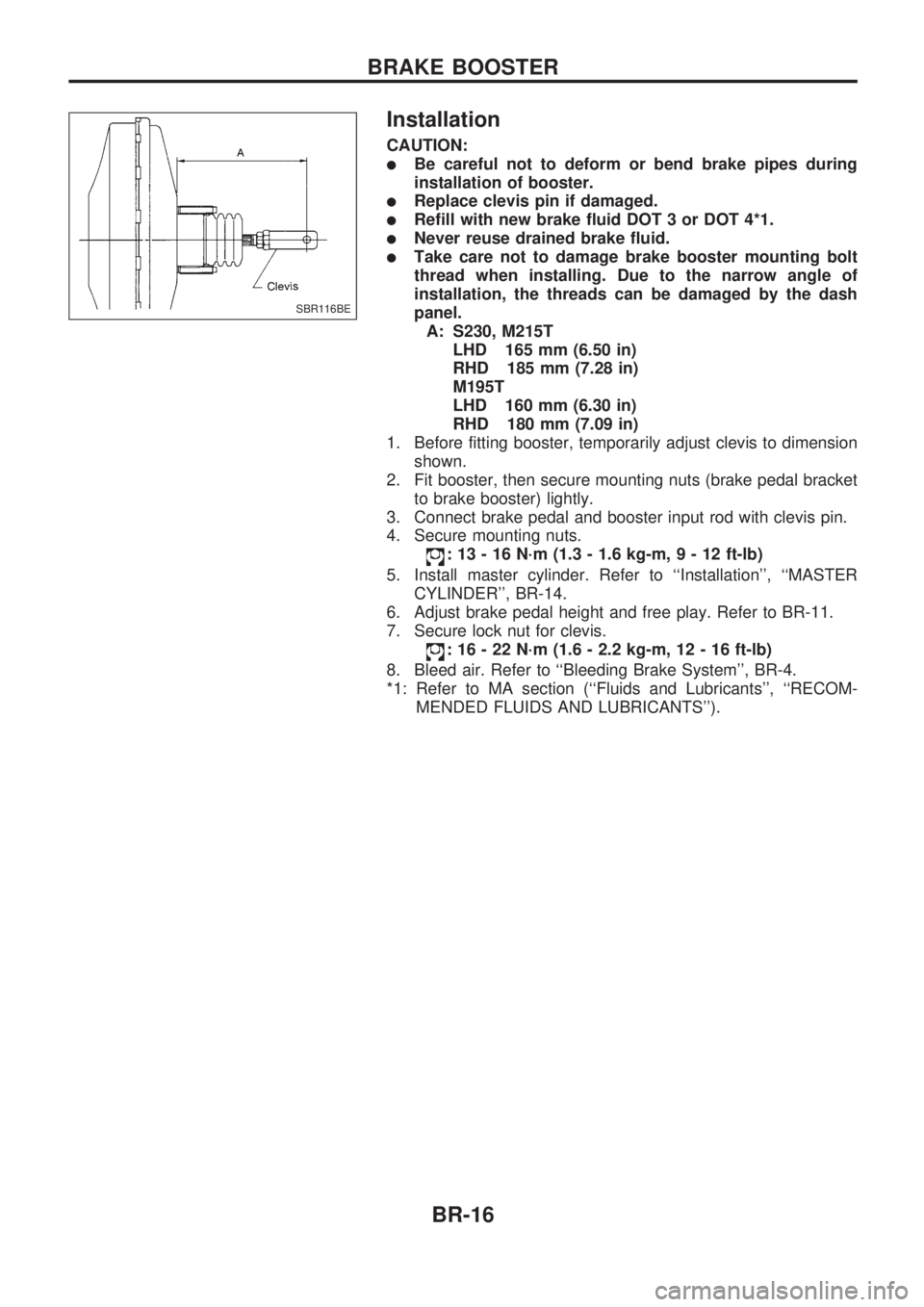
A: S230, M215T
LHD 165 mm (6.50 in)
RHD 185 mm (7.28 in)
M195T
LHD 160 mm (6.30 in)
RHD 180 mm (7.09 in)
1. Before fitting booster, temporarily adjust clevis to dimension
shown.
2. Fit booster, then secure mounting nuts (brake pedal bracket
to brake booster) lightly.
3. Connect brake pedal and booster input rod with clevis pin.
4. Secure mounting nuts.
: 13 - 16 N´m (1.3 - 1.6 kg-m,9-12ft-lb)
5. Install master cylinder. Refer to ``Installation'', ``MASTER
CYLINDER'', BR-14.
6. Adjust brake pedal height and free play. Refer to BR-11.
7. Secure lock nut for clevis.
: 16 - 22 N´m (1.6 - 2.2 kg-m, 12 - 16 ft-lb)
8. Bleed air. Refer to ``Bleeding Brake System'', BR-4.
*1: Refer to MA section (``Fluids and Lubricants'', ``RECOM-
MENDED FLUIDS AND LUBRICANTS'').
SBR116BE
BRAKE BOOSTER
BR-16
Page 37 of 1659
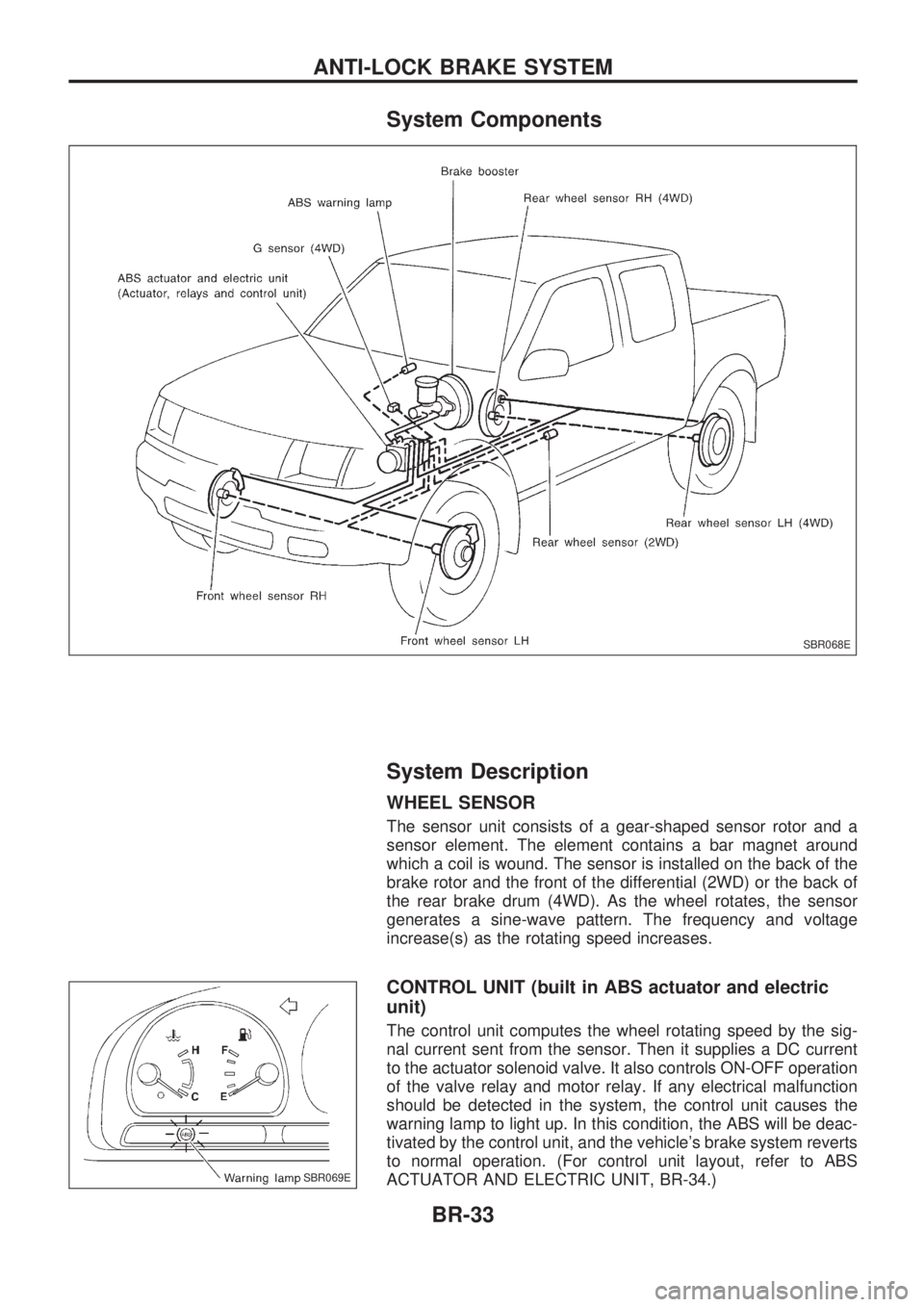
System Components
System Description
WHEEL SENSOR
The sensor unit consists of a gear-shaped sensor rotor and a
sensor element. The element contains a bar magnet around
which a coil is wound. The sensor is installed on the back of the
brake rotor and the front of the differential (2WD) or the back of
the rear brake drum (4WD). As the wheel rotates, the sensor
generates a sine-wave pattern. The frequency and voltage
increase(s) as the rotating speed increases.
CONTROL UNIT (built in ABS actuator and electric
unit)
The control unit computes the wheel rotating speed by the sig-
nal current sent from the sensor. Then it supplies a DC current
to the actuator solenoid valve. It also controls ON-OFF operation
of the valve relay and motor relay. If any electrical malfunction
should be detected in the system, the control unit causes the
warning lamp to light up. In this condition, the ABS will be deac-
tivated by the control unit, and the vehicle's brake system reverts
to normal operation. (For control unit layout, refer to ABS
ACTUATOR AND ELECTRIC UNIT, BR-34.)
SBR068E
SBR069E
ANTI-LOCK BRAKE SYSTEM
BR-33
Page 406 of 1659
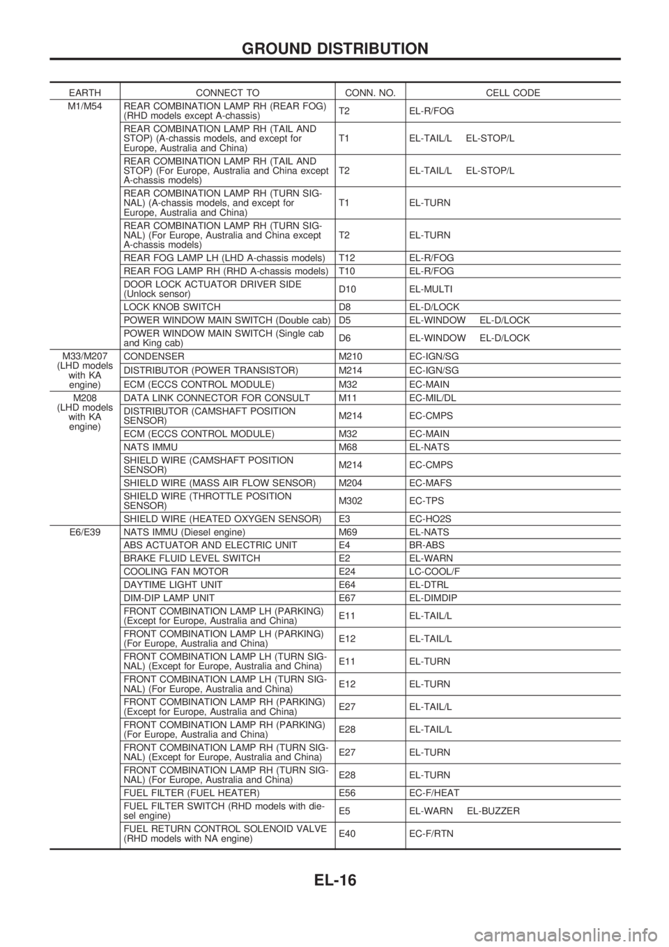
EARTH CONNECT TO CONN. NO. CELL CODE
M1/M54 REAR COMBINATION LAMP RH (REAR FOG)
(RHD models except A-chassis)T2 EL-R/FOG
REAR COMBINATION LAMP RH (TAIL AND
STOP) (A-chassis models, and except for
Europe, Australia and China)T1 EL-TAIL/L EL-STOP/L
REAR COMBINATION LAMP RH (TAIL AND
STOP) (For Europe, Australia and China except
A-chassis models)T2 EL-TAIL/L EL-STOP/L
REAR COMBINATION LAMP RH (TURN SIG-
NAL) (A-chassis models, and except for
Europe, Australia and China)T1 EL-TURN
REAR COMBINATION LAMP RH (TURN SIG-
NAL) (For Europe, Australia and China except
A-chassis models)T2 EL-TURN
REAR FOG LAMP LH (LHD A-chassis models) T12 EL-R/FOG
REAR FOG LAMP RH (RHD A-chassis models) T10 EL-R/FOG
DOOR LOCK ACTUATOR DRIVER SIDE
(Unlock sensor)D10 EL-MULTI
LOCK KNOB SWITCH D8 EL-D/LOCK
POWER WINDOW MAIN SWITCH (Double cab) D5 EL-WINDOW EL-D/LOCK
POWER WINDOW MAIN SWITCH (Single cab
and King cab)D6 EL-WINDOW EL-D/LOCK
M33/M207
(LHD models
with KA
engine)CONDENSER M210 EC-IGN/SG
DISTRIBUTOR (POWER TRANSISTOR) M214 EC-IGN/SG
ECM (ECCS CONTROL MODULE) M32 EC-MAIN
M208
(LHD models
with KA
engine)DATA LINK CONNECTOR FOR CONSULT M11 EC-MIL/DL
DISTRIBUTOR (CAMSHAFT POSITION
SENSOR)M214 EC-CMPS
ECM (ECCS CONTROL MODULE) M32 EC-MAIN
NATS IMMU M68 EL-NATS
SHIELD WIRE (CAMSHAFT POSITION
SENSOR)M214 EC-CMPS
SHIELD WIRE (MASS AIR FLOW SENSOR) M204 EC-MAFS
SHIELD WIRE (THROTTLE POSITION
SENSOR)M302 EC-TPS
SHIELD WIRE (HEATED OXYGEN SENSOR) E3 EC-HO2S
E6/E39 NATS IMMU (Diesel engine) M69 EL-NATS
ABS ACTUATOR AND ELECTRIC UNIT E4 BR-ABS
BRAKE FLUID LEVEL SWITCH E2 EL-WARN
COOLING FAN MOTOR E24 LC-COOL/F
DAYTIME LIGHT UNIT E64 EL-DTRL
DIM-DIP LAMP UNIT E67 EL-DIMDIP
FRONT COMBINATION LAMP LH (PARKING)
(Except for Europe, Australia and China)E11 EL-TAIL/L
FRONT COMBINATION LAMP LH (PARKING)
(For Europe, Australia and China)E12 EL-TAIL/L
FRONT COMBINATION LAMP LH (TURN SIG-
NAL) (Except for Europe, Australia and China)E11 EL-TURN
FRONT COMBINATION LAMP LH (TURN SIG-
NAL) (For Europe, Australia and China)E12 EL-TURN
FRONT COMBINATION LAMP RH (PARKING)
(Except for Europe, Australia and China)E27 EL-TAIL/L
FRONT COMBINATION LAMP RH (PARKING)
(For Europe, Australia and China)E28 EL-TAIL/L
FRONT COMBINATION LAMP RH (TURN SIG-
NAL) (Except for Europe, Australia and China)E27 EL-TURN
FRONT COMBINATION LAMP RH (TURN SIG-
NAL) (For Europe, Australia and China)E28 EL-TURN
FUEL FILTER (FUEL HEATER) E56 EC-F/HEAT
FUEL FILTER SWITCH (RHD models with die-
sel engine)E5 EL-WARN EL-BUZZER
FUEL RETURN CONTROL SOLENOID VALVE
(RHD models with NA engine)E40 EC-F/RTN
GROUND DISTRIBUTION
EL-16
Page 643 of 1659
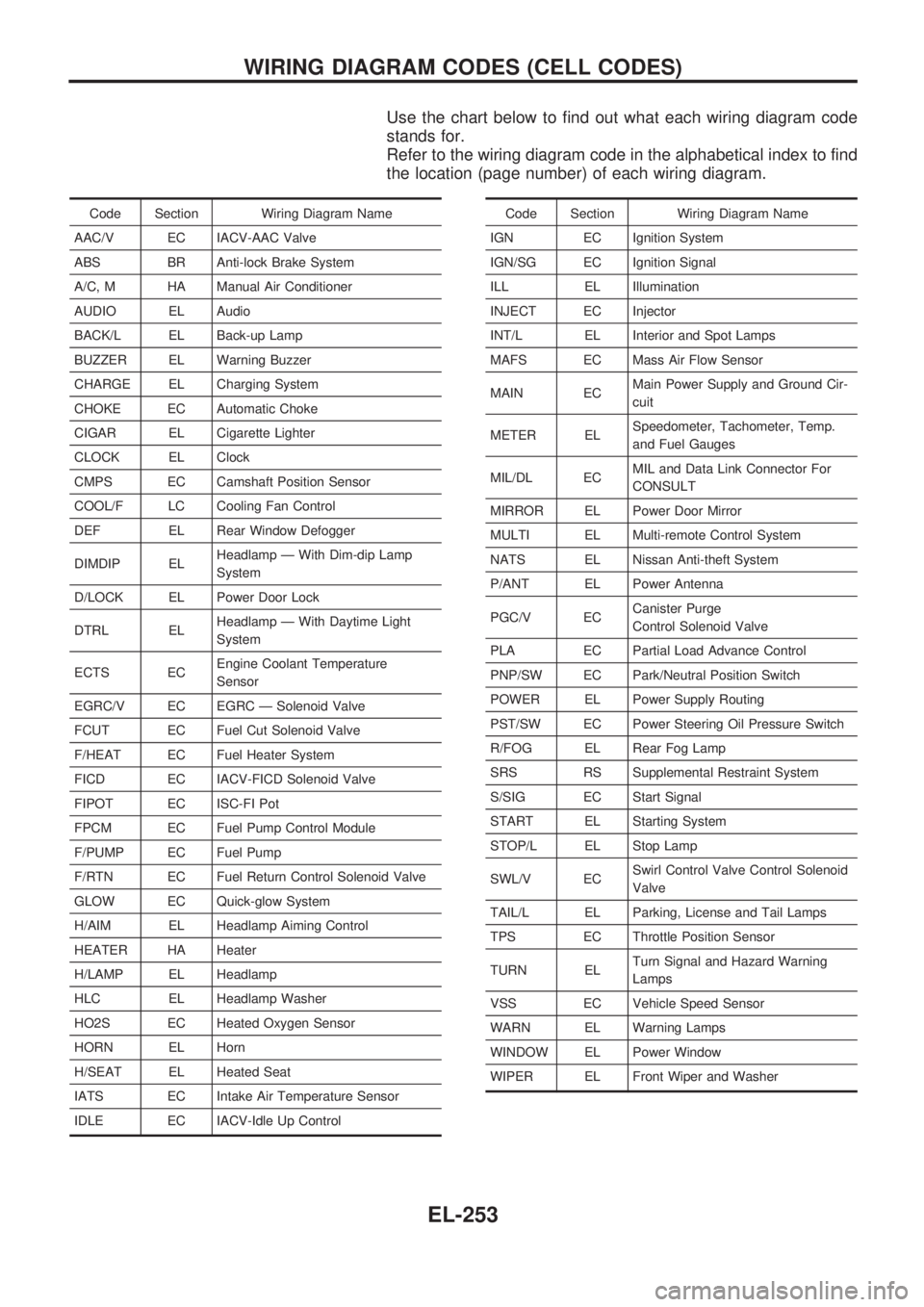
Use the chart below to find out what each wiring diagram code
stands for.
Refer to the wiring diagram code in the alphabetical index to find
the location (page number) of each wiring diagram.
Code Section Wiring Diagram Name
AAC/V EC IACV-AAC Valve
ABS BR Anti-lock Brake System
A/C, M HA Manual Air Conditioner
AUDIO EL Audio
BACK/L EL Back-up Lamp
BUZZER EL Warning Buzzer
CHARGE EL Charging System
CHOKE EC Automatic Choke
CIGAR EL Cigarette Lighter
CLOCK EL Clock
CMPS EC Camshaft Position Sensor
COOL/F LC Cooling Fan Control
DEF EL Rear Window Defogger
DIMDIP ELHeadlamp Ð With Dim-dip Lamp
System
D/LOCK EL Power Door Lock
DTRL ELHeadlamp Ð With Daytime Light
System
ECTS ECEngine Coolant Temperature
Sensor
EGRC/V EC EGRC Ð Solenoid Valve
FCUT EC Fuel Cut Solenoid Valve
F/HEAT EC Fuel Heater System
FICD EC IACV-FICD Solenoid Valve
FIPOT EC ISC-FI Pot
FPCM EC Fuel Pump Control Module
F/PUMP EC Fuel Pump
F/RTN EC Fuel Return Control Solenoid Valve
GLOW EC Quick-glow System
H/AIM EL Headlamp Aiming Control
HEATER HA Heater
H/LAMP EL Headlamp
HLC EL Headlamp Washer
HO2S EC Heated Oxygen Sensor
HORN EL Horn
H/SEAT EL Heated Seat
IATS EC Intake Air Temperature Sensor
IDLE EC IACV-Idle Up ControlCode Section Wiring Diagram Name
IGN EC Ignition System
IGN/SG EC Ignition Signal
ILL EL Illumination
INJECT EC Injector
INT/L EL Interior and Spot Lamps
MAFS EC Mass Air Flow Sensor
MAIN ECMain Power Supply and Ground Cir-
cuit
METER ELSpeedometer, Tachometer, Temp.
and Fuel Gauges
MIL/DL ECMIL and Data Link Connector For
CONSULT
MIRROR EL Power Door Mirror
MULTI EL Multi-remote Control System
NATS EL Nissan Anti-theft System
P/ANT EL Power Antenna
PGC/V ECCanister Purge
Control Solenoid Valve
PLA EC Partial Load Advance Control
PNP/SW EC Park/Neutral Position Switch
POWER EL Power Supply Routing
PST/SW EC Power Steering Oil Pressure Switch
R/FOG EL Rear Fog Lamp
SRS RS Supplemental Restraint System
S/SIG EC Start Signal
START EL Starting System
STOP/L EL Stop Lamp
SWL/V ECSwirl Control Valve Control Solenoid
Valve
TAIL/L EL Parking, License and Tail Lamps
TPS EC Throttle Position Sensor
TURN ELTurn Signal and Hazard Warning
Lamps
VSS EC Vehicle Speed Sensor
WARN EL Warning Lamps
WINDOW EL Power Window
WIPER EL Front Wiper and Washer
WIRING DIAGRAM CODES (CELL CODES)
EL-253
Page 697 of 1659
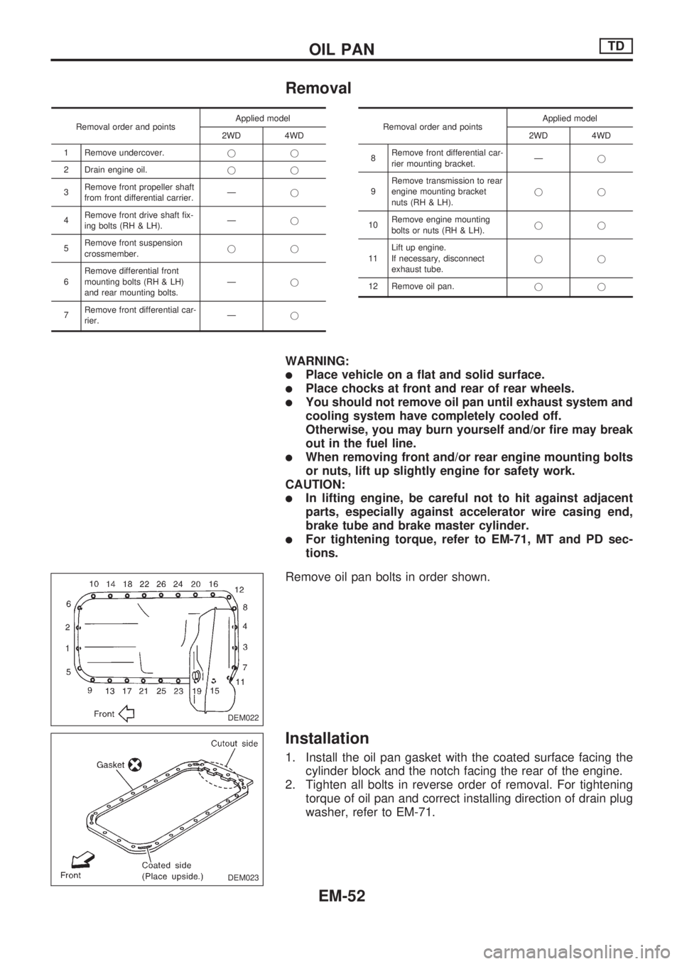
Removal
Removal order and pointsApplied model
2WD 4WD
1 Remove undercover.jj
2 Drain engine oil.jj
3Remove front propeller shaft
from front differential carrier.Ðj
4Remove front drive shaft fix-
ing bolts (RH & LH).Ðj
5Remove front suspension
crossmember.jj
6Remove differential front
mounting bolts (RH & LH)
and rear mounting bolts.Ðj
7Remove front differential car-
rier.ÐjRemoval order and pointsApplied model
2WD 4WD
8Remove front differential car-
rier mounting bracket.Ðj
9Remove transmission to rear
engine mounting bracket
nuts (RH & LH).jj
10Remove engine mounting
bolts or nuts (RH & LH).jj
11Lift up engine.
If necessary, disconnect
exhaust tube.jj
12 Remove oil pan.jj
WARNING:
lPlace vehicle on a flat and solid surface.
lPlace chocks at front and rear of rear wheels.
lYou should not remove oil pan until exhaust system and
cooling system have completely cooled off.
Otherwise, you may burn yourself and/or fire may break
out in the fuel line.
lWhen removing front and/or rear engine mounting bolts
or nuts, lift up slightly engine for safety work.
CAUTION:
lIn lifting engine, be careful not to hit against adjacent
parts, especially against accelerator wire casing end,
brake tube and brake master cylinder.
lFor tightening torque, refer to EM-71, MT and PD sec-
tions.
Remove oil pan bolts in order shown.
Installation
1. Install the oil pan gasket with the coated surface facing the
cylinder block and the notch facing the rear of the engine.
2. Tighten all bolts in reverse order of removal. For tightening
torque of oil pan and correct installing direction of drain plug
washer, refer to EM-71.
DEM022
DEM023
OIL PANTD
EM-52
Page 864 of 1659
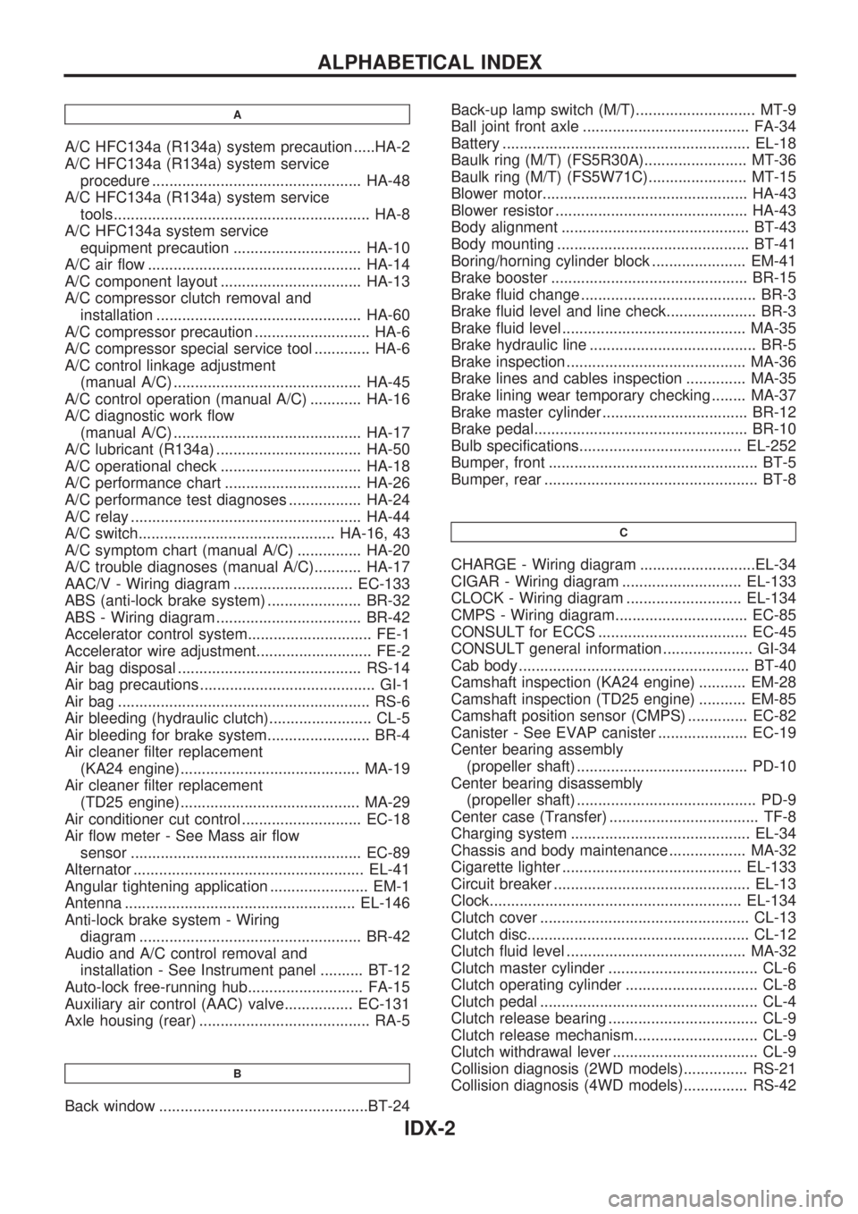
A
A/C HFC134a (R134a) system precaution .....HA-2
A/C HFC134a (R134a) system service
procedure ................................................. HA-48
A/C HFC134a (R134a) system service
tools............................................................ HA-8
A/C HFC134a system service
equipment precaution .............................. HA-10
A/C air flow .................................................. HA-14
A/C component layout ................................. HA-13
A/C compressor clutch removal and
installation ................................................ HA-60
A/C compressor precaution ........................... HA-6
A/C compressor special service tool ............. HA-6
A/C control linkage adjustment
(manual A/C) ............................................ HA-45
A/C control operation (manual A/C) ............ HA-16
A/C diagnostic work flow
(manual A/C) ............................................ HA-17
A/C lubricant (R134a) .................................. HA-50
A/C operational check ................................. HA-18
A/C performance chart ................................ HA-26
A/C performance test diagnoses ................. HA-24
A/C relay ...................................................... HA-44
A/C switch.............................................. HA-16, 43
A/C symptom chart (manual A/C) ............... HA-20
A/C trouble diagnoses (manual A/C)........... HA-17
AAC/V - Wiring diagram ............................ EC-133
ABS (anti-lock brake system) ...................... BR-32
ABS - Wiring diagram .................................. BR-42
Accelerator control system............................. FE-1
Accelerator wire adjustment........................... FE-2
Air bag disposal ........................................... RS-14
Air bag precautions ......................................... GI-1
Air bag ........................................................... RS-6
Air bleeding (hydraulic clutch)........................ CL-5
Air bleeding for brake system........................ BR-4
Air cleaner filter replacement
(KA24 engine).......................................... MA-19
Air cleaner filter replacement
(TD25 engine).......................................... MA-29
Air conditioner cut control ............................ EC-18
Air flow meter - See Mass air flow
sensor ...................................................... EC-89
Alternator ...................................................... EL-41
Angular tightening application ....................... EM-1
Antenna ...................................................... EL-146
Anti-lock brake system - Wiring
diagram .................................................... BR-42
Audio and A/C control removal and
installation - See Instrument panel .......... BT-12
Auto-lock free-running hub........................... FA-15
Auxiliary air control (AAC) valve................ EC-131
Axle housing (rear) ........................................ RA-5
B
Back window .................................................BT-24Back-up lamp switch (M/T)............................ MT-9
Ball joint front axle ....................................... FA-34
Battery .......................................................... EL-18
Baulk ring (M/T) (FS5R30A)........................ MT-36
Baulk ring (M/T) (FS5W71C)....................... MT-15
Blower motor................................................ HA-43
Blower resistor ............................................. HA-43
Body alignment ............................................ BT-43
Body mounting ............................................. BT-41
Boring/horning cylinder block ...................... EM-41
Brake booster .............................................. BR-15
Brake fluid change ......................................... BR-3
Brake fluid level and line check..................... BR-3
Brake fluid level ........................................... MA-35
Brake hydraulic line ....................................... BR-5
Brake inspection .......................................... MA-36
Brake lines and cables inspection .............. MA-35
Brake lining wear temporary checking ........ MA-37
Brake master cylinder .................................. BR-12
Brake pedal.................................................. BR-10
Bulb specifications...................................... EL-252
Bumper, front ................................................. BT-5
Bumper, rear .................................................. BT-8
C
CHARGE - Wiring diagram ...........................EL-34
CIGAR - Wiring diagram ............................ EL-133
CLOCK - Wiring diagram ........................... EL-134
CMPS - Wiring diagram............................... EC-85
CONSULT for ECCS ................................... EC-45
CONSULT general information ..................... GI-34
Cab body ...................................................... BT-40
Camshaft inspection (KA24 engine) ........... EM-28
Camshaft inspection (TD25 engine) ........... EM-85
Camshaft position sensor (CMPS) .............. EC-82
Canister - See EVAP canister ..................... EC-19
Center bearing assembly
(propeller shaft) ........................................ PD-10
Center bearing disassembly
(propeller shaft) .......................................... PD-9
Center case (Transfer) ................................... TF-8
Charging system .......................................... EL-34
Chassis and body maintenance .................. MA-32
Cigarette lighter .......................................... EL-133
Circuit breaker .............................................. EL-13
Clock........................................................... EL-134
Clutch cover ................................................. CL-13
Clutch disc.................................................... CL-12
Clutch fluid level .......................................... MA-32
Clutch master cylinder ................................... CL-6
Clutch operating cylinder ............................... CL-8
Clutch pedal ................................................... CL-4
Clutch release bearing ................................... CL-9
Clutch release mechanism............................. CL-9
Clutch withdrawal lever .................................. CL-9
Collision diagnosis (2WD models)............... RS-21
Collision diagnosis (4WD models)............... RS-42
ALPHABETICAL INDEX
IDX-2
Page 976 of 1659
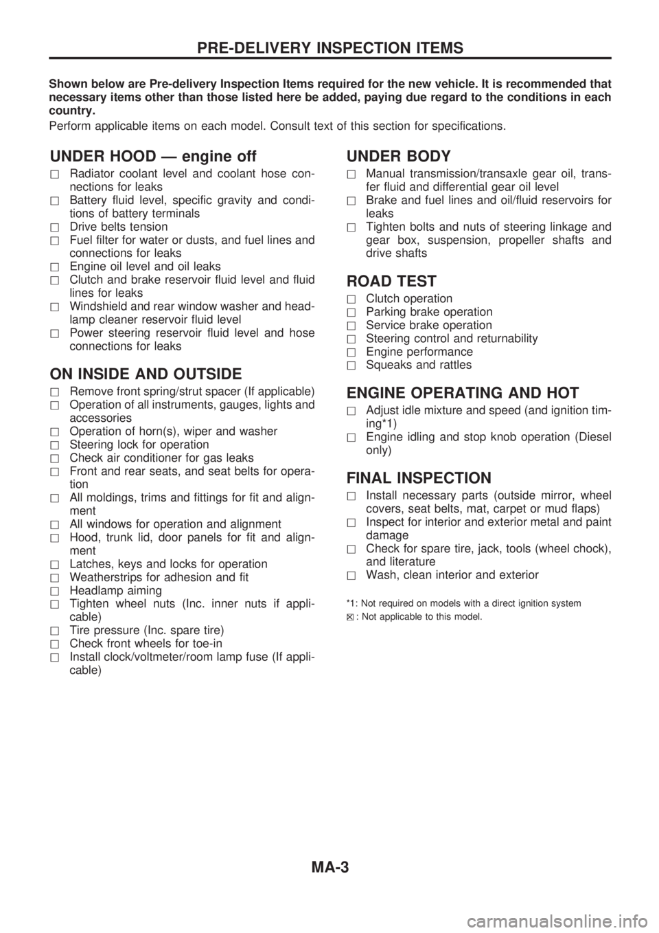
Shown below are Pre-delivery Inspection Items required for the new vehicle. It is recommended that
necessary items other than those listed here be added, paying due regard to the conditions in each
country.
Perform applicable items on each model. Consult text of this section for specifications.
UNDER HOOD Ð engine off
hRadiator coolant level and coolant hose con-
nections for leaks
hBattery fluid level, specific gravity and condi-
tions of battery terminals
hDrive belts tension
hFuel filter for water or dusts, and fuel lines and
connections for leaks
hEngine oil level and oil leaks
hClutch and brake reservoir fluid level and fluid
lines for leaks
hWindshield and rear window washer and head-
lamp cleaner reservoir fluid level
hPower steering reservoir fluid level and hose
connections for leaks
ON INSIDE AND OUTSIDE
hRemove front spring/strut spacer (If applicable)
hOperation of all instruments, gauges, lights and
accessories
hOperation of horn(s), wiper and washer
hSteering lock for operation
hCheck air conditioner for gas leaks
hFront and rear seats, and seat belts for opera-
tion
hAll moldings, trims and fittings for fit and align-
ment
hAll windows for operation and alignment
hHood, trunk lid, door panels for fit and align-
ment
hLatches, keys and locks for operation
hWeatherstrips for adhesion and fit
hHeadlamp aiming
hTighten wheel nuts (Inc. inner nuts if appli-
cable)
hTire pressure (Inc. spare tire)
hCheck front wheels for toe-in
hInstall clock/voltmeter/room lamp fuse (If appli-
cable)
UNDER BODY
hManual transmission/transaxle gear oil, trans-
fer fluid and differential gear oil level
hBrake and fuel lines and oil/fluid reservoirs for
leaks
hTighten bolts and nuts of steering linkage and
gear box, suspension, propeller shafts and
drive shafts
ROAD TEST
hClutch operation
hParking brake operation
hService brake operation
hSteering control and returnability
hEngine performance
hSqueaks and rattles
ENGINE OPERATING AND HOT
hAdjust idle mixture and speed (and ignition tim-
ing*1)
hEngine idling and stop knob operation (Diesel
only)
FINAL INSPECTION
hInstall necessary parts (outside mirror, wheel
covers, seat belts, mat, carpet or mud flaps)
hInspect for interior and exterior metal and paint
damage
hCheck for spare tire, jack, tools (wheel chock),
and literature
hWash, clean interior and exterior
*1: Not required on models with a direct ignition system
h
X: Not applicable to this model.
PRE-DELIVERY INSPECTION ITEMS
MA-3
Page 977 of 1659
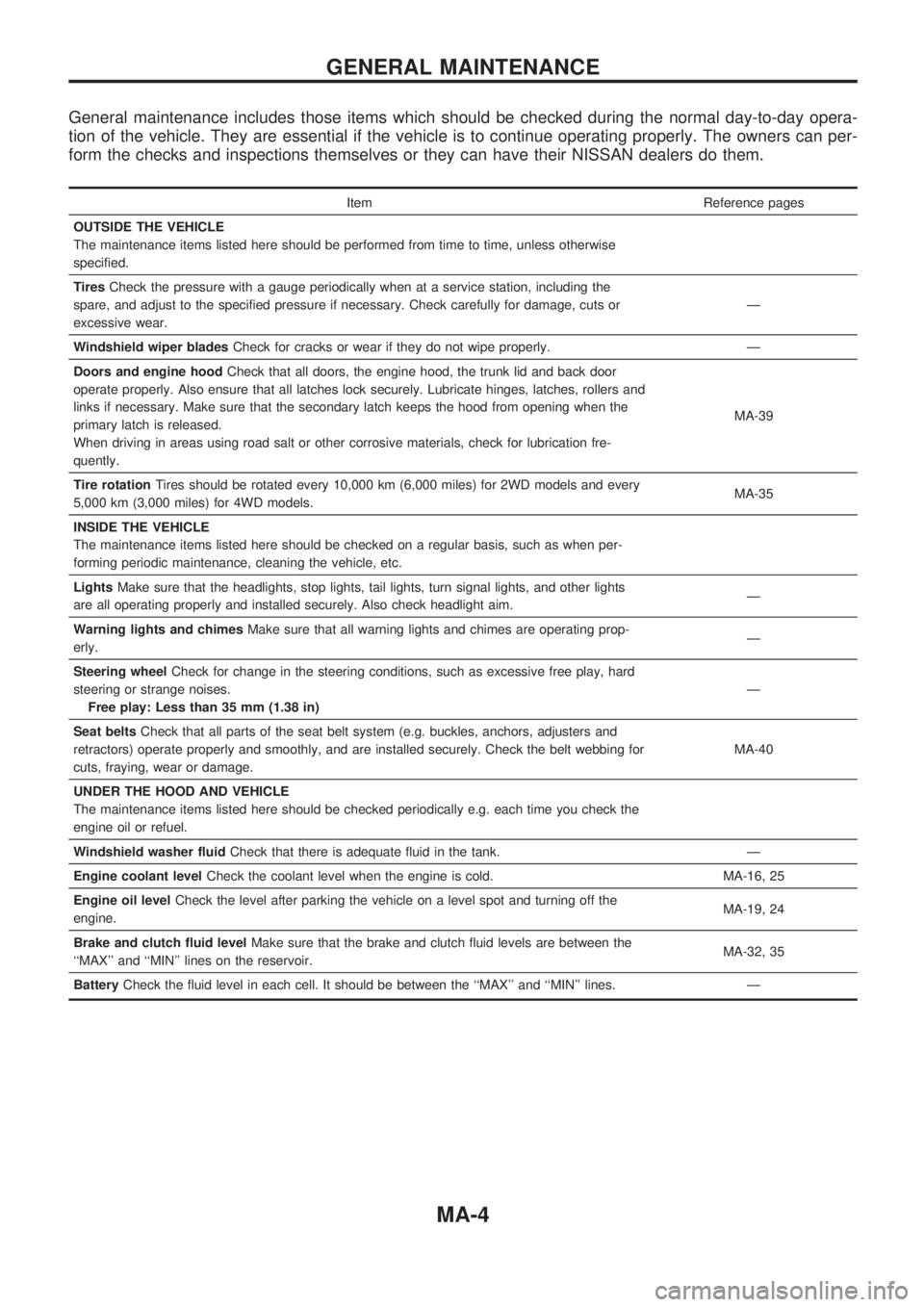
General maintenance includes those items which should be checked during the normal day-to-day opera-
tion of the vehicle. They are essential if the vehicle is to continue operating properly. The owners can per-
form the checks and inspections themselves or they can have their NISSAN dealers do them.
Item Reference pages
OUTSIDE THE VEHICLE
The maintenance items listed here should be performed from time to time, unless otherwise
specified.
TiresCheck the pressure with a gauge periodically when at a service station, including the
spare, and adjust to the specified pressure if necessary. Check carefully for damage, cuts or
excessive wear.Ð
Windshield wiper bladesCheck for cracks or wear if they do not wipe properly. Ð
Doors and engine hoodCheck that all doors, the engine hood, the trunk lid and back door
operate properly. Also ensure that all latches lock securely. Lubricate hinges, latches, rollers and
links if necessary. Make sure that the secondary latch keeps the hood from opening when the
primary latch is released.
When driving in areas using road salt or other corrosive materials, check for lubrication fre-
quently.MA-39
Tire rotationTires should be rotated every 10,000 km (6,000 miles) for 2WD models and every
5,000 km (3,000 miles) for 4WD models.MA-35
INSIDE THE VEHICLE
The maintenance items listed here should be checked on a regular basis, such as when per-
forming periodic maintenance, cleaning the vehicle, etc.
LightsMake sure that the headlights, stop lights, tail lights, turn signal lights, and other lights
are all operating properly and installed securely. Also check headlight aim.Ð
Warning lights and chimesMake sure that all warning lights and chimes are operating prop-
erly.Ð
Steering wheelCheck for change in the steering conditions, such as excessive free play, hard
steering or strange noises.
Free play: Less than 35 mm (1.38 in)Ð
Seat beltsCheck that all parts of the seat belt system (e.g. buckles, anchors, adjusters and
retractors) operate properly and smoothly, and are installed securely. Check the belt webbing for
cuts, fraying, wear or damage.MA-40
UNDER THE HOOD AND VEHICLE
The maintenance items listed here should be checked periodically e.g. each time you check the
engine oil or refuel.
Windshield washer fluidCheck that there is adequate fluid in the tank. Ð
Engine coolant levelCheck the coolant level when the engine is cold. MA-16, 25
Engine oil levelCheck the level after parking the vehicle on a level spot and turning off the
engine.MA-19, 24
Brake and clutch fluid levelMake sure that the brake and clutch fluid levels are between the
``MAX'' and ``MIN'' lines on the reservoir.MA-32, 35
BatteryCheck the fluid level in each cell. It should be between the ``MAX'' and ``MIN'' lines. Ð
GENERAL MAINTENANCE
MA-4