bulb NISSAN PICK-UP 1998 Repair Manual
[x] Cancel search | Manufacturer: NISSAN, Model Year: 1998, Model line: PICK-UP, Model: NISSAN PICK-UP 1998Pages: 1659, PDF Size: 53.39 MB
Page 43 of 1659
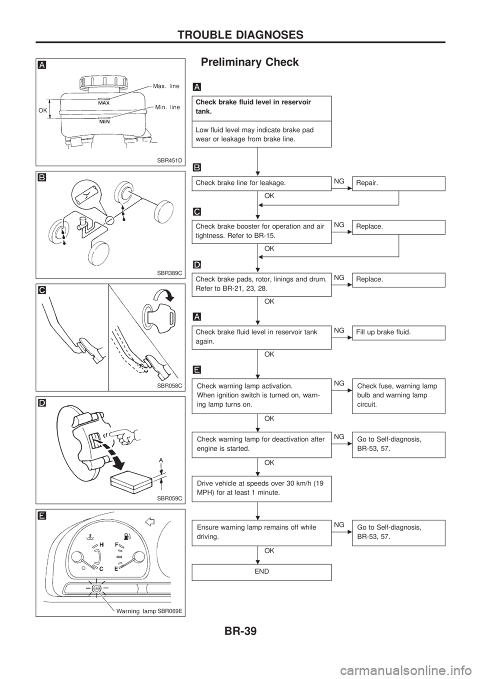
Preliminary Check
Check brake fluid level in reservoir
tank.
-------------------------------------------------------------------------------------------------------------------------------------------------------------------------------------------------------------------------------------------------------------------------------------------------------------
Low fluid level may indicate brake pad
wear or leakage from brake line.
Check brake line for leakage.
OKcNG
Repair.
b
Check brake booster for operation and air
tightness. Refer to BR-15.
OK
cNG
Replace.
b
Check brake pads, rotor, linings and drum.
Refer to BR-21, 23, 28.
OK
cNG
Replace.
Check brake fluid level in reservoir tank
again.
OK
cNG
Fill up brake fluid.
Check warning lamp activation.
When ignition switch is turned on, warn-
ing lamp turns on.
OK
cNG
Check fuse, warning lamp
bulb and warning lamp
circuit.
Check warning lamp for deactivation after
engine is started.
OK
cNG
Go to Self-diagnosis,
BR-53, 57.
Drive vehicle at speeds over 30 km/h (19
MPH) for at least 1 minute.
Ensure warning lamp remains off while
driving.
OK
cNG
Go to Self-diagnosis,
BR-53, 57.
END
SBR451D
SBR389C
SBR058C
SBR059C
SBR069E
.
.
.
.
.
.
.
.
.
TROUBLE DIAGNOSES
BR-39
Page 59 of 1659
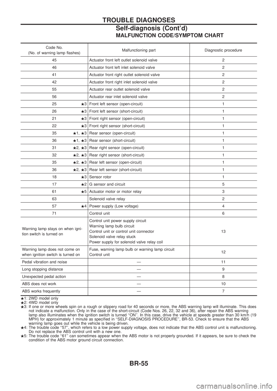
MALFUNCTION CODE/SYMPTOM CHART
Code No.
(No. of warning lamp flashes)Malfunctioning part Diagnostic procedure
45 Actuator front left outlet solenoid valve 2
46 Actuator front left inlet solenoid valve 2
41 Actuator front right outlet solenoid valve 2
42 Actuator front right inlet solenoid valve 2
55 Actuator rear outlet solenoid valve 2
56 Actuator rear inlet solenoid valve 2
25.3 Front left sensor (open-circuit) 1
26.3 Front left sensor (short-circuit) 1
21.3 Front right sensor (open-circuit) 1
22.3 Front right sensor (short-circuit) 1
35.1,.3 Rear sensor (open-circuit) 1
36.1,.3 Rear sensor (short-circuit) 1
31.2,.3 Rear right sensor (open-circuit) 1
32.2,.3 Rear right sensor (short-circuit) 1
35.2,.3 Rear left sensor (open-circuit) 1
36.2,.3 Rear left sensor (short-circuit) 1
18.3 Sensor rotor 1
17.2 G sensor and circuit 5
61.5 Actuator motor or motor relay 3
63 Solenoid valve relay 2
57.4 Power supply (Low voltage) 4
71 Control unit 6
Warning lamp stays on when igni-
tion switch is turned onControl unit power supply circuit
Warning lamp bulb circuit
Control unit or control unit connector
Solenoid valve relay stuck
Power supply for solenoid valve relay coil13
Warning lamp does not come on
when ignition switch is turned onFuse, warning lamp bulb or warning lamp circuit
Control unit12
Pedal vibration and noise Ð 11
Long stopping distance Ð 9
Unexpected pedal action Ð 8
ABS does not work Ð 10
ABS works frequently Ð 7
.1: 2WD model only
.2: 4WD model only
.3: If one or more wheels spin on a rough or slippery road for 40 seconds or more, the ABS warning lamp will illuminate. This does
not indicate a malfunction. Only in the case of the short-circuit (Code Nos. 26, 22, 32 and 36), after repair the ABS warning
lamp also illuminates when the ignition switch is turned ``ON''. In this case, drive the vehicle at speeds greater than 30 km/h (19
MPH) for approximately 1 minute as specified in ``SELF-DIAGNOSIS PROCEDURE'', BR-53. Check to ensure that the ABS
warning lamp goes out while the vehicle is being driven.
.4: The trouble code ``57'', which refers to a low power supply voltage, does not indicate that the ABS control unit is malfunctioning.
Do not replace the ABS control unit with a new one.
.5: The trouble code ``61'' can sometimes appear when the ABS motor is not properly grounded. If it appears, be sure to check the
condition of the ABS motor ground circuit connection.
TROUBLE DIAGNOSES
Self-diagnosis (Cont'd)
BR-55
Page 190 of 1659
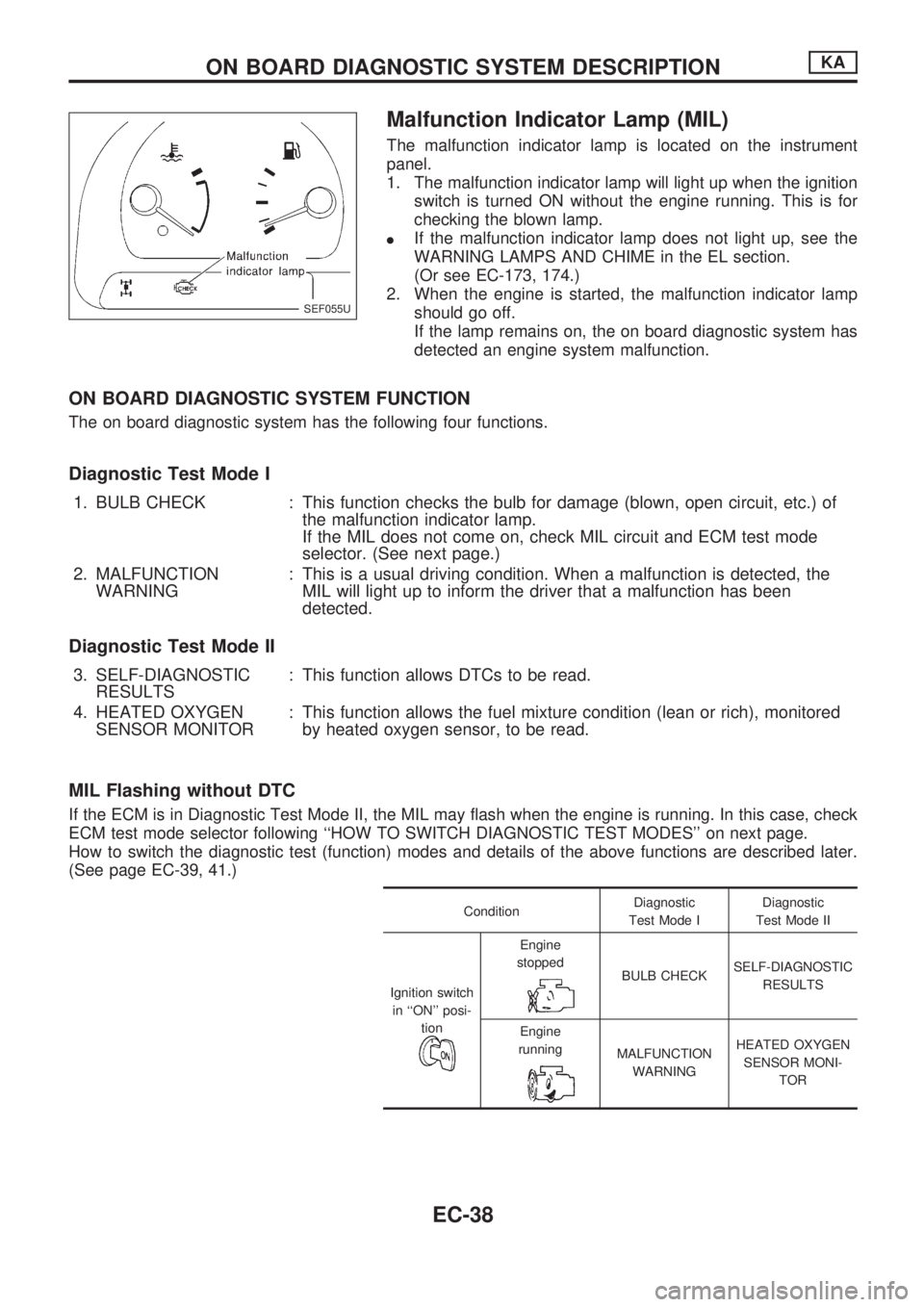
Malfunction Indicator Lamp (MIL)
The malfunction indicator lamp is located on the instrument
panel.
1. The malfunction indicator lamp will light up when the ignition
switch is turned ON without the engine running. This is for
checking the blown lamp.
lIf the malfunction indicator lamp does not light up, see the
WARNING LAMPS AND CHIME in the EL section.
(Or see EC-173, 174.)
2. When the engine is started, the malfunction indicator lamp
should go off.
If the lamp remains on, the on board diagnostic system has
detected an engine system malfunction.
ON BOARD DIAGNOSTIC SYSTEM FUNCTION
The on board diagnostic system has the following four functions.
Diagnostic Test Mode I
1. BULB CHECK : This function checks the bulb for damage (blown, open circuit, etc.) of
the malfunction indicator lamp.
If the MIL does not come on, check MIL circuit and ECM test mode
selector. (See next page.)
2. MALFUNCTION
WARNING: This is a usual driving condition. When a malfunction is detected, the
MIL will light up to inform the driver that a malfunction has been
detected.
Diagnostic Test Mode II
3. SELF-DIAGNOSTIC
RESULTS: This function allows DTCs to be read.
4. HEATED OXYGEN
SENSOR MONITOR: This function allows the fuel mixture condition (lean or rich), monitored
by heated oxygen sensor, to be read.
MIL Flashing without DTC
If the ECM is in Diagnostic Test Mode II, the MIL may flash when the engine is running. In this case, check
ECM test mode selector following ``HOW TO SWITCH DIAGNOSTIC TEST MODES'' on next page.
How to switch the diagnostic test (function) modes and details of the above functions are described later.
(See page EC-39, 41.)
ConditionDiagnostic
Test Mode IDiagnostic
Test Mode II
Ignition switch
in ``ON'' posi-
tion
Engine
stopped
BULB CHECKSELF-DIAGNOSTIC
RESULTS
Engine
running
MALFUNCTION
WARNINGHEATED OXYGEN
SENSOR MONI-
TOR
SEF055U
ON BOARD DIAGNOSTIC SYSTEM DESCRIPTIONKA
EC-38
Page 191 of 1659
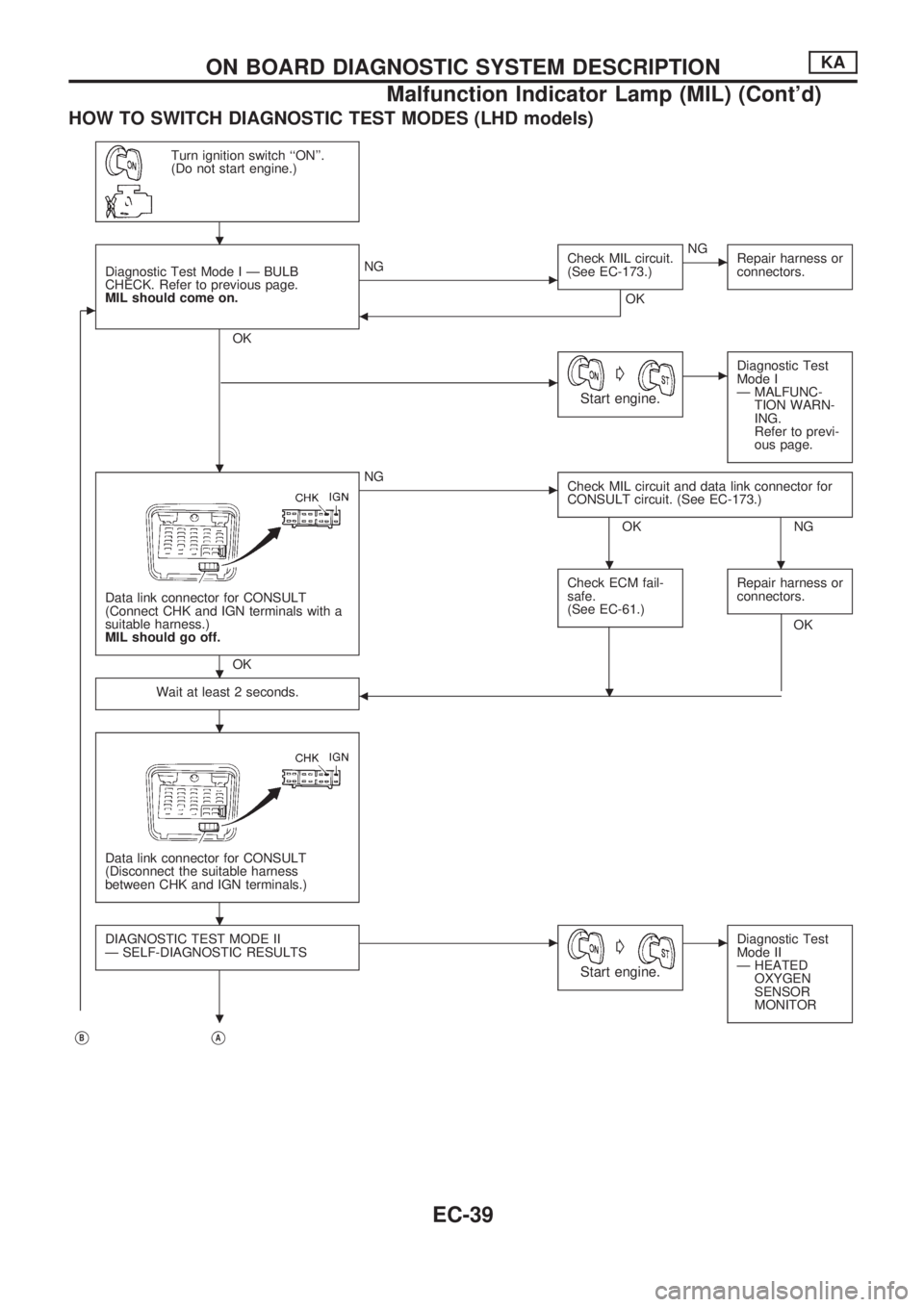
HOW TO SWITCH DIAGNOSTIC TEST MODES (LHD models)
Turn ignition switch ``ON''.
(Do not start engine.)
c
Diagnostic Test Mode I Ð BULB
CHECK. Refer to previous page.
MIL should come on.
OK
cNGCheck MIL circuit.
(See EC-173.)
OK
cNG
Repair harness or
connectors.
b
cG
Start engine.
cDiagnostic Test
Mode I
Ð MALFUNC-
TION WARN-
ING.
Refer to previ-
ous page.
Data link connector for CONSULT
(Connect CHK and IGN terminals with a
suitable harness.)
MIL should go off.
OK
cNG
Check MIL circuit and data link connector for
CONSULT circuit. (See EC-173.)
OK NG
Check ECM fail-
safe.
(See EC-61.)
Repair harness or
connectors.
OK
Wait at least 2 seconds.
b
Data link connector for CONSULT
(Disconnect the suitable harness
between CHK and IGN terminals.)
DIAGNOSTIC TEST MODE II
Ð SELF-DIAGNOSTIC RESULTScG
Start engine.
cDiagnostic Test
Mode II
Ð HEATED
OXYGEN
SENSOR
MONITOR
VBVA
.
.
..
.
.
.
.
.
ON BOARD DIAGNOSTIC SYSTEM DESCRIPTIONKA
Malfunction Indicator Lamp (MIL) (Cont'd)
EC-39
Page 193 of 1659
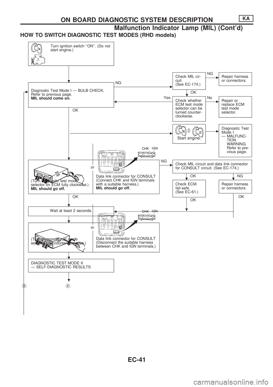
HOW TO SWITCH DIAGNOSTIC TEST MODES (RHD models)
Turn ignition switch ``ON''. (Do not
start engine.)
cDiagnostic Test Mode I Ð BULB CHECK.
Refer to previous page.
MIL should come on.
OK
cNGCheck MIL cir-
cuit.
(See EC-174.)
OK
cNG
Repair harness
or connectors.
bYes
Check whether
ECM test mode
selector can be
turned counter-
clockwise.cNo
Repair or
replace ECM
test mode
selector.
cG
Start engine.
cDiagnostic Test
Mode I
Ð MALFUNC-
TION
WARNING.
Refer to pre-
vious page.
Data link connector for CONSULT
(Connect CHK and IGN terminals
with a suitable harness.)
MIL should go off. (Turn diagnostic test mode
selector on ECM fully clockwise.)
MIL should go off.or
OK
cNG
Check MIL circuit and data link connector
for CONSULT circuit. (See EC-174.)
OK NG
Check ECM
fail-safe.
(See EC-61.)
OKRepair harness
or connectors.OK
Wait at least 2 seconds.
b
Data link connector for CONSULT
(Disconnect the suitable harness
between CHK and IGN terminals.) (Turn diagnostic test mode
selector fully counterclockwise.)or
DIAGNOSTIC TEST MODE II
Ð SELF-DIAGNOSTIC RESULTS
VBVA
.
.
.
..
.
.
.
.
.
ON BOARD DIAGNOSTIC SYSTEM DESCRIPTIONKA
Malfunction Indicator Lamp (MIL) (Cont'd)
EC-41
Page 195 of 1659
DIAGNOSTIC TEST MODE IÐBULB CHECK
In this mode, the MALFUNCTION INDICATOR LAMP on the instrument panel should stay ON. If it remains
OFF, check the bulb. (See the WARNING LAMPS AND CHIME in the EL section. Or see EC-173, 174.)
DIAGNOSTIC TEST MODE IÐMALFUNCTION WARNING
MALFUNCTION
INDICATOR LAMPCondition
ON When the malfunction is detected (Refer to EC-1.) or the ECM's CPU is malfunctioning.
OFF No malfunction
lThese Diagnostic Trouble Code Numbers are clarified in Diagnostic Test Mode II (SELF-DIAGNOSTIC
RESULTS).
DIAGNOSTIC TEST MODE IIÐSELF-DIAGNOSTIC RESULTS
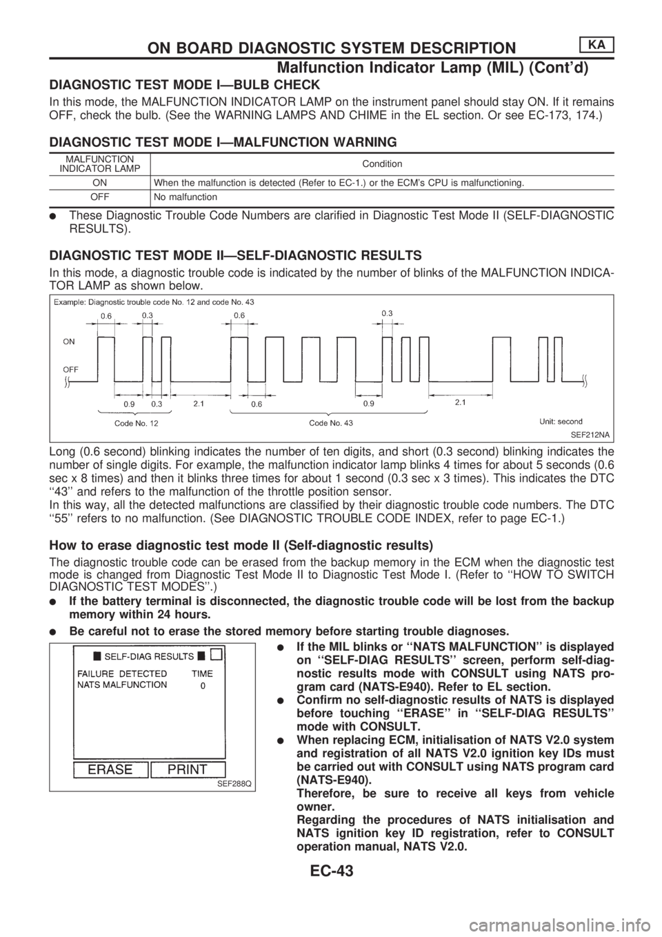
In this mode, a diagnostic trouble code is indicated by the number of blinks of the MALFUNCTION INDICA-
TOR LAMP as shown below.
Long (0.6 second) blinking indicates the number of ten digits, and short (0.3 second) blinking indicates the
number of single digits. For example, the malfunction indicator lamp blinks 4 times for about 5 seconds (0.6
sec x 8 times) and then it blinks three times for about 1 second (0.3 sec x 3 times). This indicates the DTC
``43'' and refers to the malfunction of the throttle position sensor.
In this way, all the detected malfunctions are classified by their diagnostic trouble code numbers. The DTC
``55'' refers to no malfunction. (See DIAGNOSTIC TROUBLE CODE INDEX, refer to page EC-1.)
How to erase diagnostic test mode II (Self-diagnostic results)
The diagnostic trouble code can be erased from the backup memory in the ECM when the diagnostic test
mode is changed from Diagnostic Test Mode II to Diagnostic Test Mode I. (Refer to ``HOW TO SWITCH
DIAGNOSTIC TEST MODES''.)
lIf the battery terminal is disconnected, the diagnostic trouble code will be lost from the backup
memory within 24 hours.
lBe careful not to erase the stored memory before starting trouble diagnoses.
lIf the MIL blinks or ``NATS MALFUNCTION'' is displayed
on ``SELF-DIAG RESULTS'' screen, perform self-diag-
nostic results mode with CONSULT using NATS pro-
gram card (NATS-E940). Refer to EL section.
lConfirm no self-diagnostic results of NATS is displayed
before touching ``ERASE'' in ``SELF-DIAG RESULTS''
mode with CONSULT.
lWhen replacing ECM, initialisation of NATS V2.0 system
and registration of all NATS V2.0 ignition key IDs must
be carried out with CONSULT using NATS program card
(NATS-E940).
Therefore, be sure to receive all keys from vehicle
owner.
Regarding the procedures of NATS initialisation and
NATS ignition key ID registration, refer to CONSULT
operation manual, NATS V2.0.
SEF212NA
SEF288Q
ON BOARD DIAGNOSTIC SYSTEM DESCRIPTIONKA
Malfunction Indicator Lamp (MIL) (Cont'd)
EC-43
Page 388 of 1659
ELECTRICAL SYSTEM
SECTION
EL
When you read wiring diagrams:
lRead GI section, ``HOW TO READ WIRING DIAGRAMS''.
When you perform trouble diagnoses, read GI section, ``HOW TO FOLLOW FLOW CHART IN
TROUBLE DIAGNOSES'' and ``HOW TO PERFORM EFFICIENT DIAGNOSIS FOR AN ELECTRI-
CAL INCIDENT''.
CONTENTS
PRECAUTIONS......................................................... 1
Supplemental Restraint System (SRS) ``AIR
BAG'' (4WD models).............................................. 1
Supplemental Restraint System (SRS) ``AIR
BAG'' (2WD models).............................................. 1
HARNESS CONNECTOR.......................................... 2
Description ............................................................. 2
STANDARDIZED RELAY.......................................... 3
Description ............................................................. 3
POWER SUPPLY ROUTING..................................... 5
Schematic .............................................................. 5
Wiring Diagram - POWER -................................... 6
Fuse ..................................................................... 13
Fusible Link .......................................................... 13
Circuit Breaker Inspection.................................... 13
GROUND DISTRIBUTION....................................... 14
BATTERY................................................................. 18
How to Handle Battery......................................... 18
Battery Test and Charging Chart......................... 21
Service Data and Specifications (SDS) ............... 25
STARTING SYSTEM............................................... 26
Wiring Diagram - START - .................................. 26
Trouble Diagnoses ............................................... 27
Construction ......................................................... 28
Removal and Installation ..................................... 30
Inspection ............................................................. 30
Assembly.............................................................. 32
Service Data and Specifications (SDS) ............... 33
CHARGING SYSTEM.............................................. 34
Wiring Diagram - CHARGE -/Gasoline Engine ... 34
Wiring Diagram - CHARGE -/Diesel Engine ....... 35Trouble Diagnoses ............................................... 36
Construction ......................................................... 38
Removal and Installation ..................................... 39
Disassembly ......................................................... 39
Inspection ............................................................. 39
Assembly.............................................................. 40
Service Data and Specifications (SDS) ............... 41
COMBINATION SWITCH........................................ 42
Check ................................................................... 42
Replacement ........................................................ 43
HEADLAMP - Conventional Type -....................... 44
Wiring Diagram - H/LAMP -/LHD Models ............ 44
Wiring Diagram - H/LAMP -/RHD Models ........... 46
Trouble Diagnoses ............................................... 48
Bulb Replacement................................................ 49
Aiming Adjustment ............................................... 49
Low Beam ............................................................ 50
HEADLAMP - Daytime Light System -................. 51
System Description .............................................. 51
Schematic ............................................................ 53
Wiring Diagram - DTRL - ..................................... 54
Trouble Diagnoses ............................................... 57
Bulb Replacement................................................ 57
Aiming Adjustment ............................................... 57
HEADLAMP - Dim-dip Lamp System -................. 58
System Description .............................................. 58
Schematic ............................................................ 58
Wiring Diagram - DIMDIP -.................................. 59
Trouble Diagnoses ............................................... 62
Bulb Replacement................................................ 62
Aiming Adjustment ............................................... 62
EL
Page 390 of 1659
Wiring Diagram - MULTI -/LHD Models ............ 175
Trouble Diagnoses ............................................. 179
ID Code Entry Procedure .................................. 182
NATS (Nissan Anti-Theft System)/Gasoline
engine for LHD models........................................ 183
Component Parts and Harness Connector
Location.............................................................. 183
System Description ............................................ 183
System Composition .......................................... 184
Wiring Diagram - NATS -................................... 185
CONSULT .......................................................... 186
Trouble Diagnoses ............................................. 188
How to Replace NATS IMMU ............................ 197
NATS (Nissan Anti-Theft System)/Diesel
engine.................................................................... 198
Component Parts and Harness Connector
Location.............................................................. 198
System Description ............................................ 199
System Composition .......................................... 199
Wiring Diagram - NATS -/LHD Models.............. 200
Wiring Diagram - NATS -/RHD Models ............. 201
CONSULT .......................................................... 202
Trouble Diagnoses ............................................. 205LOCATION OF ELECTRICAL UNITS................... 217
Engine Compartment ......................................... 217
Passenger Compartment ................................... 218
HARNESS LAYOUT.............................................. 220
Outline ................................................................ 220
How to Read Harness Layout ........................... 221
Main Harness ..................................................... 222
Engine Room Harness....................................... 232
Engine Control Harness..................................... 240
Engine Harness ................................................. 242
Alternator Harness ............................................. 244
Instrument Harness............................................ 245
Room Lamp Harness/LHD Models .................... 246
Room Lamp Harness/RHD Models ................... 247
Chassis Harness and Tail Harness ................... 248
Front Door Harness (LH side) ........................... 249
Front Door Harness (RH side)........................... 250
Rear Door Harness ............................................ 251
BULB SPECIFICATIONS...................................... 252
Headlamp ........................................................... 252
Exterior Lamp..................................................... 252
Interior Lamp ...................................................... 252
WIRING DIAGRAM CODES (CELL CODES)....... 253
WIRING DIAGRAM REFERENCE CHART
COOLING FAN .......................................................................................................... LC SECTION
ECCS, IGNITION SYSTEM, QUICK-GLOW SYSTEM, FUEL HEATER SYSTEM .. EC SECTION
ANTI-LOCK BRAKE SYSTEM .................................................................................. BR SECTION
SRS ``AIR BAG'' ........................................................................................................ RS SECTION
HEATER AND AIR CONDITIONER .......................................................................... HA SECTION
Page 426 of 1659
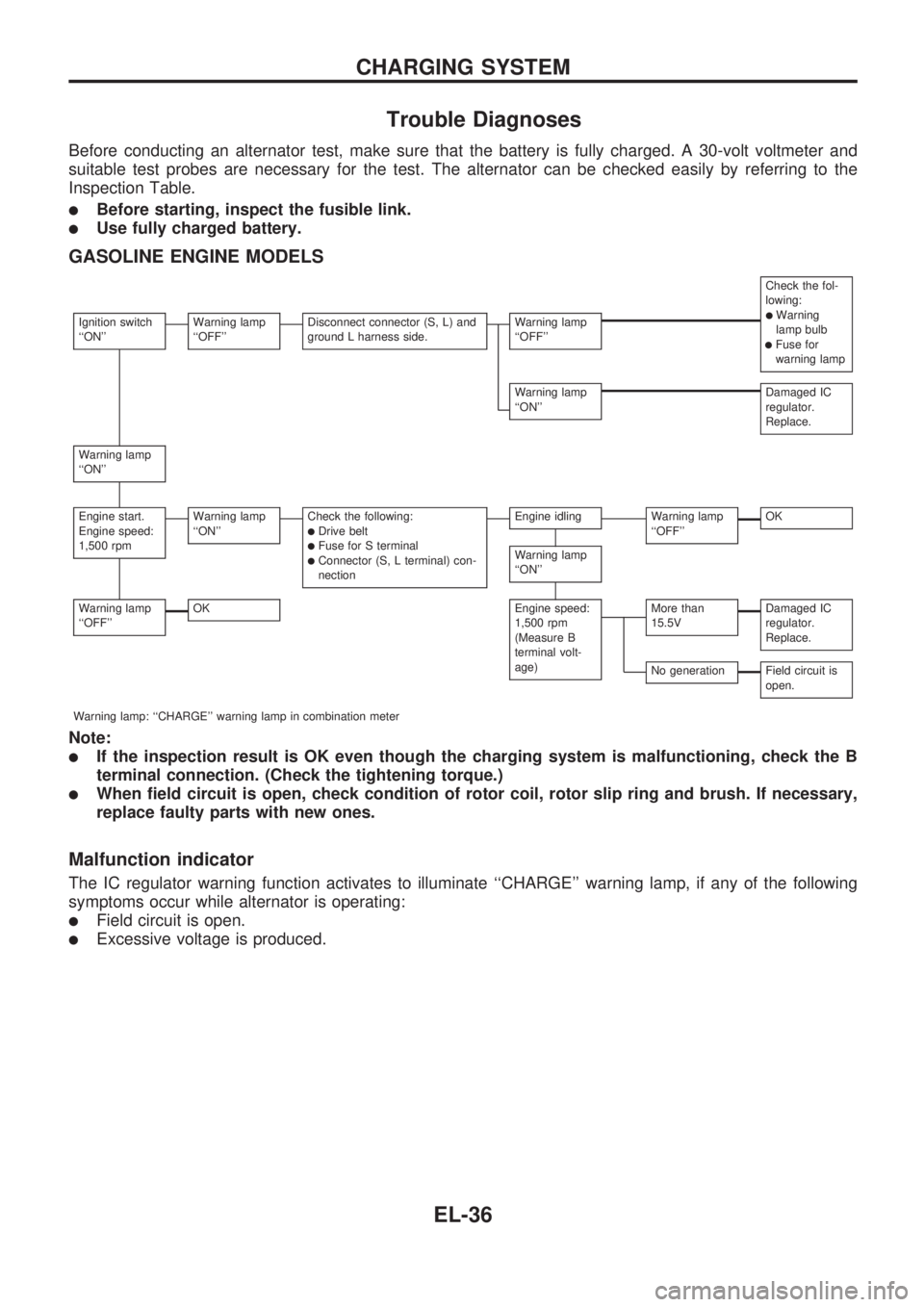
Trouble Diagnoses
Before conducting an alternator test, make sure that the battery is fully charged. A 30-volt voltmeter and
suitable test probes are necessary for the test. The alternator can be checked easily by referring to the
Inspection Table.
lBefore starting, inspect the fusible link.
lUse fully charged battery.
GASOLINE ENGINE MODELS
Check the fol-
lowing:
lWarning
lamp bulb
lFuse for
warning lamp
Ignition switch
``ON''Warning lamp
``OFF''Disconnect connector (S, L) and
ground L harness side.Warning lamp
``OFF''
Warning lamp
``ON''Damaged IC
regulator.
Replace.
Warning lamp
``ON''
Engine start.
Engine speed:
1,500 rpmWarning lamp
``ON''Check the following:lDrive beltlFuse for S terminallConnector (S, L terminal) con-
nection
Engine idlingWarning lamp
``OFF''OK
Warning lamp
``ON''
Warning lamp
``OFF''OKEngine speed:
1,500 rpm
(Measure B
terminal volt-
age)More than
15.5VDamaged IC
regulator.
Replace.
No generationField circuit is
open.
Warning lamp: ``CHARGE'' warning lamp in combination meter
Note:
lIf the inspection result is OK even though the charging system is malfunctioning, check the B
terminal connection. (Check the tightening torque.)
lWhen field circuit is open, check condition of rotor coil, rotor slip ring and brush. If necessary,
replace faulty parts with new ones.
Malfunction indicator
The IC regulator warning function activates to illuminate ``CHARGE'' warning lamp, if any of the following
symptoms occur while alternator is operating:
lField circuit is open.
lExcessive voltage is produced.
CHARGING SYSTEM
EL-36
Page 427 of 1659
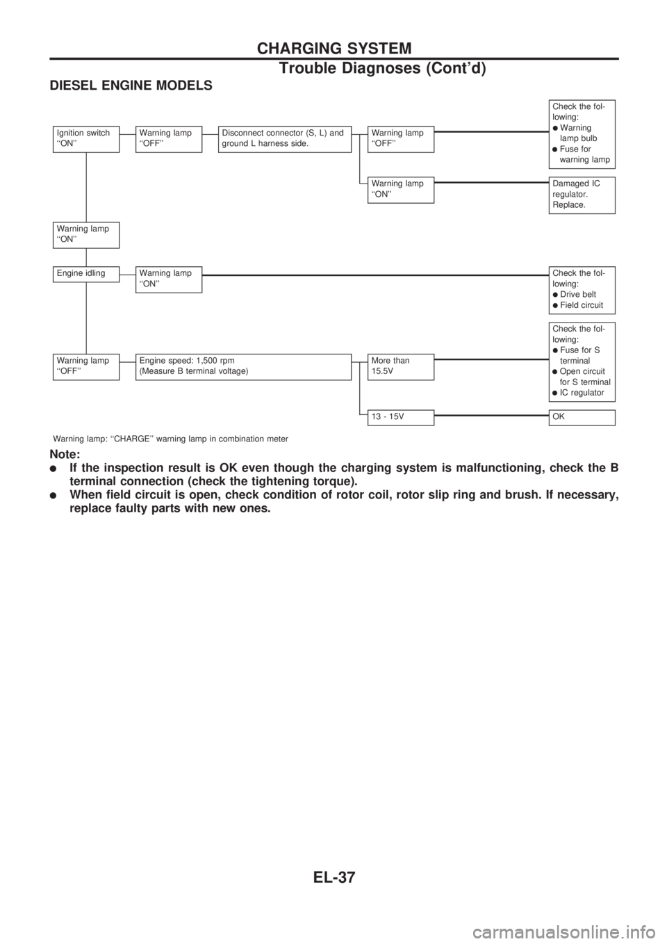
DIESEL ENGINE MODELS
Check the fol-
lowing:
lWarning
lamp bulb
lFuse for
warning lamp
Ignition switch
``ON''Warning lamp
``OFF''Disconnect connector (S, L) and
ground L harness side.Warning lamp
``OFF''
Warning lamp
``ON''Damaged IC
regulator.
Replace.
Warning lamp
``ON''
Engine idlingWarning lamp
``ON''Check the fol-
lowing:
lDrive beltlField circuit
Check the fol-
lowing:
lFuse for S
terminal
lOpen circuit
for S terminal
lIC regulator
Warning lamp
``OFF''Engine speed: 1,500 rpm
(Measure B terminal voltage)More than
15.5V
13 - 15VOK
Warning lamp: ``CHARGE'' warning lamp in combination meter
Note:
lIf the inspection result is OK even though the charging system is malfunctioning, check the B
terminal connection (check the tightening torque).
lWhen field circuit is open, check condition of rotor coil, rotor slip ring and brush. If necessary,
replace faulty parts with new ones.
CHARGING SYSTEM
Trouble Diagnoses (Cont'd)
EL-37