change time NISSAN PICK-UP 1998 Repair Manual
[x] Cancel search | Manufacturer: NISSAN, Model Year: 1998, Model line: PICK-UP, Model: NISSAN PICK-UP 1998Pages: 1659, PDF Size: 53.39 MB
Page 2 of 1659
FOREWORD
This manual contains maintenance and repair procedures for NISSAN
PICKUP, model D22 series.
In order to assure your safety and the efficient functioning of the vehicle,
this manual should be read thoroughly. It is especially important that the
PRECAUTIONS in the GI section be completely understood before starting
any repair task.
All information in this manual is based on the latest product information
at the time of publication. The right is reserved to make changes in speci-
®cations and methods at any time without notice.
IMPORTANT SAFETY NOTICE
The proper performance of service is essential for both the safety of the
technician and the efficient functioning of the vehicle.
The service methods in this Service Manual are described in such a man-
ner that the service may be performed safely and accurately.
Service varies with the procedures used, the skills of the technician and the
tools and parts available. Accordingly, anyone using service procedures,
tools or parts which are not speci®cally recommended by NISSAN must
®rst completely satisfy himself that neither his safety nor the vehicle's
safety will be jeopardized by the service method selected.
NISSAN EUROPE S.A.S.
Service Engineering Section
Paris, France
Page 19 of 1659
On-vehicle Service
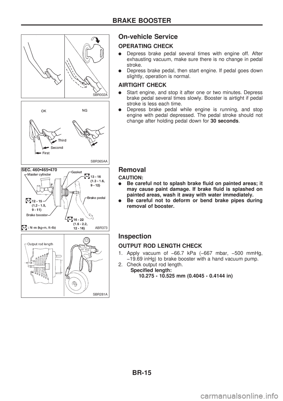
OPERATING CHECK
lDepress brake pedal several times with engine off. After
exhausting vacuum, make sure there is no change in pedal
stroke.
lDepress brake pedal, then start engine. If pedal goes down
slightly, operation is normal.
AIRTIGHT CHECK
lStart engine, and stop it after one or two minutes. Depress
brake pedal several times slowly. Booster is airtight if pedal
stroke is less each time.
lDepress brake pedal while engine is running, and stop
engine with pedal depressed. The pedal stroke should not
change after holding pedal down for30 seconds.
Removal
CAUTION:
lBe careful not to splash brake fluid on painted areas; it
may cause paint damage. If brake fluid is splashed on
painted areas, wash it away with water immediately.
lBe careful not to deform or bend brake pipes during
removal of booster.
Inspection
OUTPUT ROD LENGTH CHECK
1. Apply vacuum of þ66.7 kPa (þ667 mbar, þ500 mmHg,
þ19.69 inHg) to brake booster with a hand vacuum pump.
2. Check output rod length.
Specified length:
10.275 - 10.525 mm (0.4045 - 0.4144 in)
SBR002A
SBR365AA
ABR373
SBR281A
BRAKE BOOSTER
BR-15
Page 174 of 1659
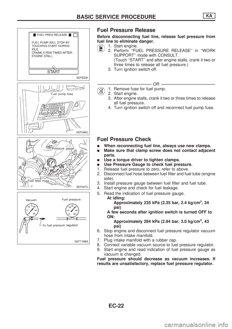
Fuel Pressure Release
Before disconnecting fuel line, release fuel pressure from
fuel line to eliminate danger.
1. Start engine.
2. Perform ``FUEL PRESSURE RELEASE'' in ``WORK
SUPPORT'' mode with CONSULT.
(Touch ``START'' and after engine stalls, crank it two or
three times to release all fuel pressure.)
3. Turn ignition switch off.
-------------------------------------------------------------------------------------------------------------------------------------------------------------------------------------------------------------------------------------------------OR-------------------------------------------------------------------------------------------------------------------------------------------------------------------------------------------------------------------------------------------------
1. Remove fuse for fuel pump.
2. Start engine.
3. After engine stalls, crank it two or three times to release
all fuel pressure.
4. Turn ignition switch off and reconnect fuel pump fuse.
Fuel Pressure Check
lWhen reconnecting fuel line, always use new clamps.
lMake sure that clamp screw does not contact adjacent
parts.
lUse a torque driver to tighten clamps.
lUse Pressure Gauge to check fuel pressure.
1. Release fuel pressure to zero, refer to above.
2. Disconnect fuel hose between fuel filter and fuel tube (engine
side).
3. Install pressure gauge between fuel filter and fuel tube.
4. Start engine and check for fuel leakage.
5. Read the indication of fuel pressure gauge.
At idling:
Approximately 235 kPa (2.35 bar, 2.4 kg/cm
2,34
psi)
A few seconds after ignition switch is turned OFF to
ON:
Approximately 294 kPa (2.94 bar, 3.0 kg/cm
2,43
psi)
6. Stop engine and disconnect fuel pressure regulator vacuum
hose from intake manifold.
7. Plug intake manifold with a rubber cap.
8. Connect variable vacuum source to fuel pressure regulator.
9. Start engine and read indication of fuel pressure gauge as
vacuum is changed.
Fuel pressure should decrease as vacuum increases. If
results are unsatisfactory, replace fuel pressure regulator.
SEF823K
SEF046U
SEF047U
SEF718BA
BASIC SERVICE PROCEDUREKA
EC-22
Page 195 of 1659
DIAGNOSTIC TEST MODE IÐBULB CHECK
In this mode, the MALFUNCTION INDICATOR LAMP on the instrument panel should stay ON. If it remains
OFF, check the bulb. (See the WARNING LAMPS AND CHIME in the EL section. Or see EC-173, 174.)
DIAGNOSTIC TEST MODE IÐMALFUNCTION WARNING
MALFUNCTION
INDICATOR LAMPCondition
ON When the malfunction is detected (Refer to EC-1.) or the ECM's CPU is malfunctioning.
OFF No malfunction
lThese Diagnostic Trouble Code Numbers are clarified in Diagnostic Test Mode II (SELF-DIAGNOSTIC
RESULTS).
DIAGNOSTIC TEST MODE IIÐSELF-DIAGNOSTIC RESULTS
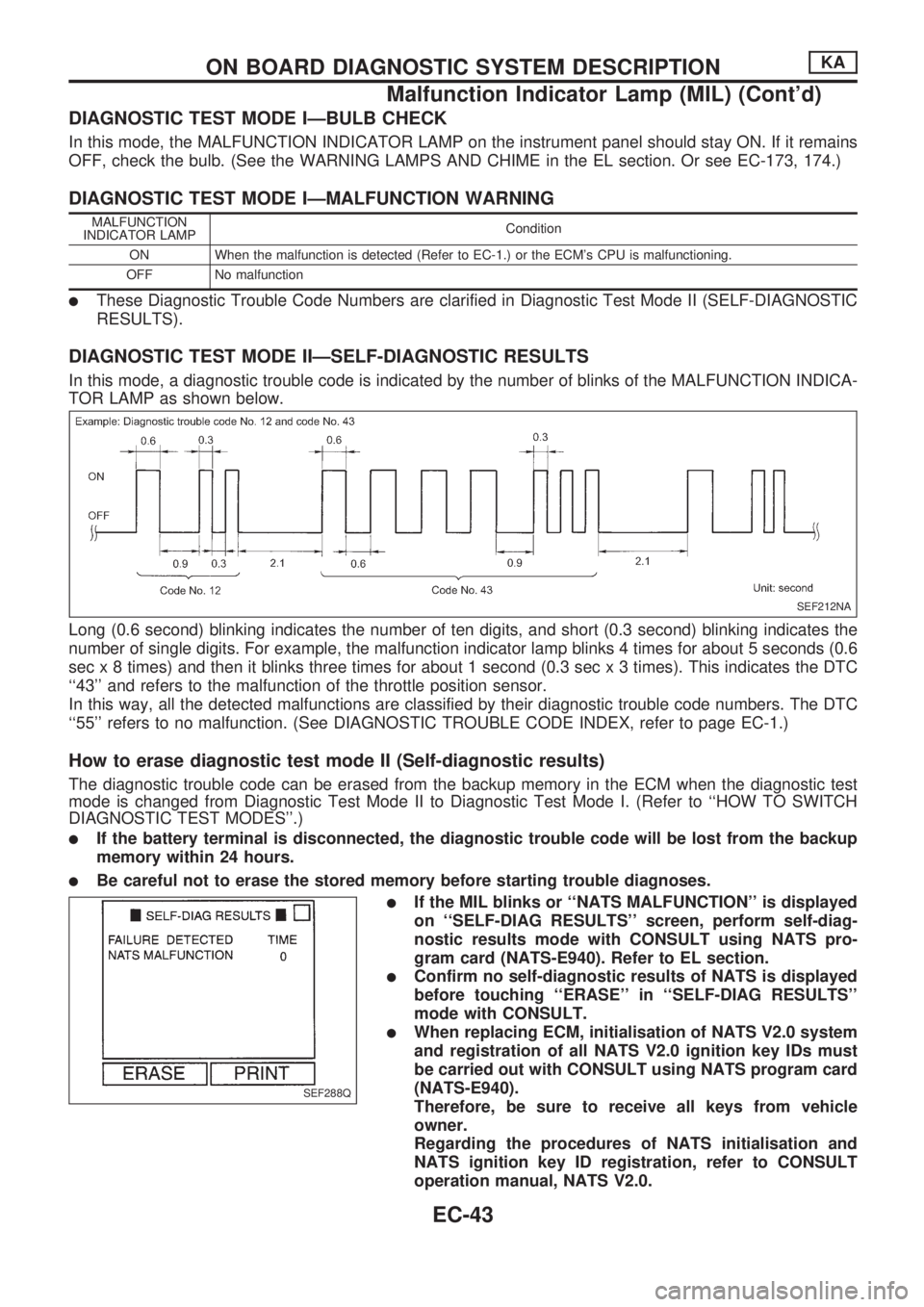
In this mode, a diagnostic trouble code is indicated by the number of blinks of the MALFUNCTION INDICA-
TOR LAMP as shown below.
Long (0.6 second) blinking indicates the number of ten digits, and short (0.3 second) blinking indicates the
number of single digits. For example, the malfunction indicator lamp blinks 4 times for about 5 seconds (0.6
sec x 8 times) and then it blinks three times for about 1 second (0.3 sec x 3 times). This indicates the DTC
``43'' and refers to the malfunction of the throttle position sensor.
In this way, all the detected malfunctions are classified by their diagnostic trouble code numbers. The DTC
``55'' refers to no malfunction. (See DIAGNOSTIC TROUBLE CODE INDEX, refer to page EC-1.)
How to erase diagnostic test mode II (Self-diagnostic results)
The diagnostic trouble code can be erased from the backup memory in the ECM when the diagnostic test
mode is changed from Diagnostic Test Mode II to Diagnostic Test Mode I. (Refer to ``HOW TO SWITCH
DIAGNOSTIC TEST MODES''.)
lIf the battery terminal is disconnected, the diagnostic trouble code will be lost from the backup
memory within 24 hours.
lBe careful not to erase the stored memory before starting trouble diagnoses.
lIf the MIL blinks or ``NATS MALFUNCTION'' is displayed
on ``SELF-DIAG RESULTS'' screen, perform self-diag-
nostic results mode with CONSULT using NATS pro-
gram card (NATS-E940). Refer to EL section.
lConfirm no self-diagnostic results of NATS is displayed
before touching ``ERASE'' in ``SELF-DIAG RESULTS''
mode with CONSULT.
lWhen replacing ECM, initialisation of NATS V2.0 system
and registration of all NATS V2.0 ignition key IDs must
be carried out with CONSULT using NATS program card
(NATS-E940).
Therefore, be sure to receive all keys from vehicle
owner.
Regarding the procedures of NATS initialisation and
NATS ignition key ID registration, refer to CONSULT
operation manual, NATS V2.0.
SEF212NA
SEF288Q
ON BOARD DIAGNOSTIC SYSTEM DESCRIPTIONKA
Malfunction Indicator Lamp (MIL) (Cont'd)
EC-43
Page 202 of 1659
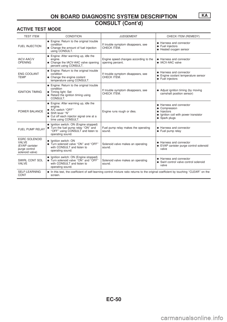
ACTIVE TEST MODE
TEST ITEM CONDITION JUDGEMENT CHECK ITEM (REMEDY)
FUEL INJECTION
lEngine: Return to the original trouble
condition
lChange the amount of fuel injection
using CONSULT.If trouble symptom disappears, see
CHECK ITEM.
lHarness and connectorlFuel injectorslHeated oxygen sensor
IACV-AAC/V
OPENING
lEngine: After warming up, idle the
engine.
lChange the IACV-AAC valve opening
percent using CONSULT.Engine speed changes according to the
opening percent.lHarness and connectorlIACV-AAC valve
ENG COOLANT
TEMP
lEngine: Return to the original trouble
condition
lChange the engine coolant
temperature using CONSULT.If trouble symptom disappears, see
CHECK ITEM.
lHarness and connectorlEngine coolant temperature sensorlFuel injectors
IGNITION TIMING
lEngine: Return to the original trouble
condition
lTiming light: SetlRetard the ignition timing using
CONSULT.If trouble symptom disappears, see
CHECK ITEM.
lAdjust ignition timing (by moving
camshaft position sensor)
POWER BALANCE
lEngine: After warming up, idle the
engine.
lA/C switch ``OFF''lShift lever ``N''lCut off each injector signal one at a
time using CONSULT.Engine runs rough or dies.
lHarness and connectorlCompressionlInjectorslIgnition coil with power transistorlSpark plugs
FUEL PUMP RELAY
lIgnition switch: ON (Engine stopped)lTurn the fuel pump relay ``ON'' and
``OFF'' using CONSULT and listen to
operating sound.Fuel pump relay makes the operating
sound.lHarness and connectorlFuel pump relay
EGRC SOLENOID
VALVE
(EVAP canister
purge control
solenoid valve)
lIgnition switch: ONlTurn solenoid valve ``ON'' and ``OFF''
with CONSULT and listen to
operating sound.Solenoid valve makes an operating
sound.lHarness and connectorlEVAP canister purge control solenoid
valve
SWIRL CONT SOL
VALVE
lIgnition switch: ON (Engine stopped)lTurn solenoid valve ``ON'' and ``OFF''
with CONSULT and listen to
operating sound.Solenoid valve makes an operating
sound.lHarness and connectorlSwirl control valve control solenoid
valve
SELF-LEARNING
CONT
lIn this test, the coefficient of self-learning control mixture ratio returns to the original coefficient by touching ``CLEAR'' on the
screen.
ON BOARD DIAGNOSTIC SYSTEM DESCRIPTIONKA
CONSULT (Cont'd)
EC-50
Page 204 of 1659
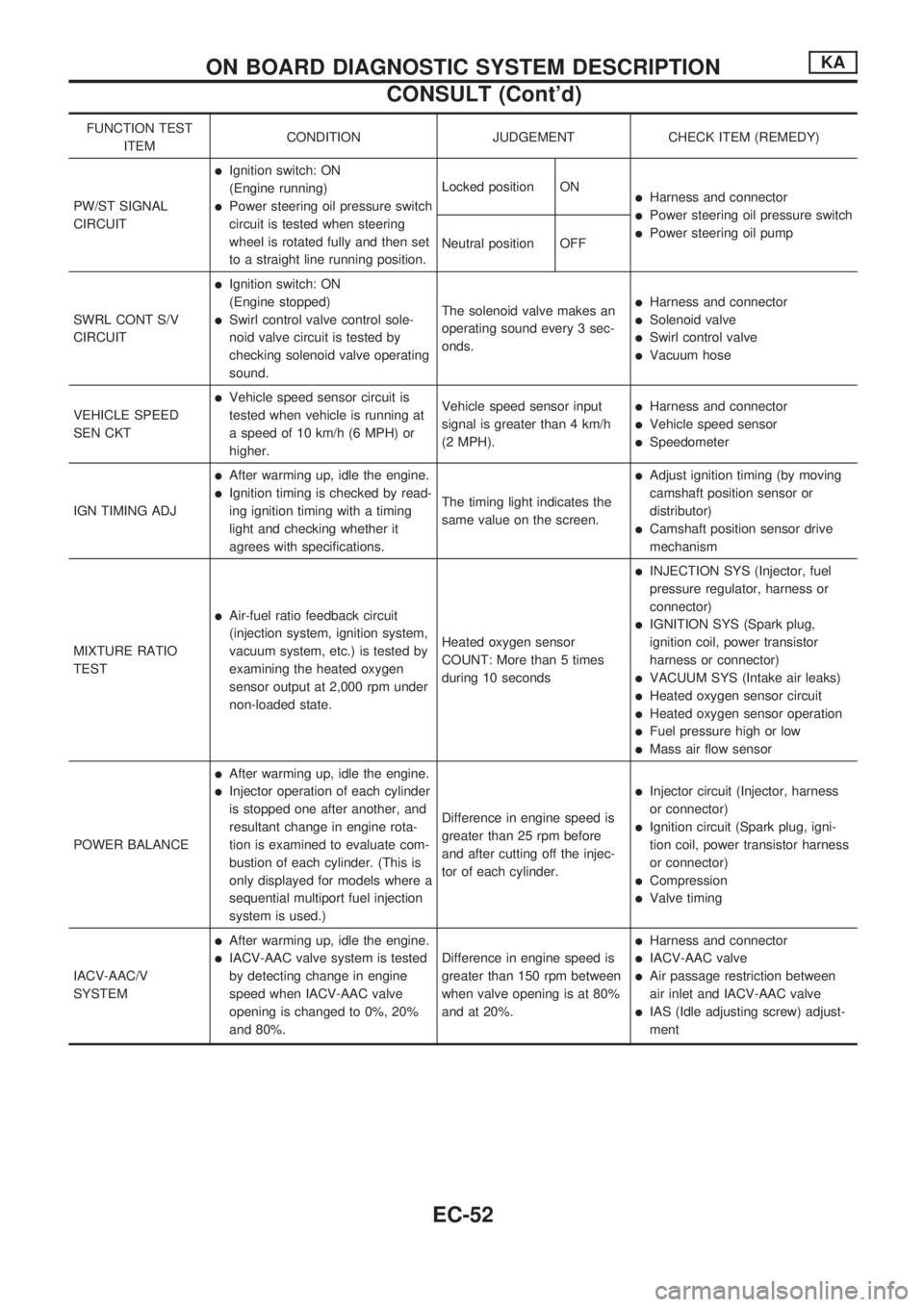
FUNCTION TEST
ITEMCONDITION JUDGEMENT CHECK ITEM (REMEDY)
PW/ST SIGNAL
CIRCUIT
lIgnition switch: ON
(Engine running)
lPower steering oil pressure switch
circuit is tested when steering
wheel is rotated fully and then set
to a straight line running position.Locked position ONlHarness and connector
lPower steering oil pressure switch
lPower steering oil pump
Neutral position OFF
SWRL CONT S/V
CIRCUIT
lIgnition switch: ON
(Engine stopped)
lSwirl control valve control sole-
noid valve circuit is tested by
checking solenoid valve operating
sound.The solenoid valve makes an
operating sound every 3 sec-
onds.
lHarness and connector
lSolenoid valve
lSwirl control valve
lVacuum hose
VEHICLE SPEED
SEN CKT
lVehicle speed sensor circuit is
tested when vehicle is running at
a speed of 10 km/h (6 MPH) or
higher.Vehicle speed sensor input
signal is greater than 4 km/h
(2 MPH).lHarness and connector
lVehicle speed sensor
lSpeedometer
IGN TIMING ADJ
lAfter warming up, idle the engine.
lIgnition timing is checked by read-
ing ignition timing with a timing
light and checking whether it
agrees with specifications.The timing light indicates the
same value on the screen.
lAdjust ignition timing (by moving
camshaft position sensor or
distributor)
lCamshaft position sensor drive
mechanism
MIXTURE RATIO
TEST
lAir-fuel ratio feedback circuit
(injection system, ignition system,
vacuum system, etc.) is tested by
examining the heated oxygen
sensor output at 2,000 rpm under
non-loaded state.Heated oxygen sensor
COUNT: More than 5 times
during 10 seconds
lINJECTION SYS (Injector, fuel
pressure regulator, harness or
connector)
lIGNITION SYS (Spark plug,
ignition coil, power transistor
harness or connector)
lVACUUM SYS (Intake air leaks)
lHeated oxygen sensor circuit
lHeated oxygen sensor operation
lFuel pressure high or low
lMass air flow sensor
POWER BALANCE
lAfter warming up, idle the engine.
lInjector operation of each cylinder
is stopped one after another, and
resultant change in engine rota-
tion is examined to evaluate com-
bustion of each cylinder. (This is
only displayed for models where a
sequential multiport fuel injection
system is used.)Difference in engine speed is
greater than 25 rpm before
and after cutting off the injec-
tor of each cylinder.lInjector circuit (Injector, harness
or connector)
lIgnition circuit (Spark plug, igni-
tion coil, power transistor harness
or connector)
lCompression
lValve timing
IACV-AAC/V
SYSTEM
lAfter warming up, idle the engine.
lIACV-AAC valve system is tested
by detecting change in engine
speed when IACV-AAC valve
opening is changed to 0%, 20%
and 80%.Difference in engine speed is
greater than 150 rpm between
when valve opening is at 80%
and at 20%.
lHarness and connector
lIACV-AAC valve
lAir passage restriction between
air inlet and IACV-AAC valve
lIAS (Idle adjusting screw) adjust-
ment
ON BOARD DIAGNOSTIC SYSTEM DESCRIPTIONKA
CONSULT (Cont'd)
EC-52
Page 211 of 1659
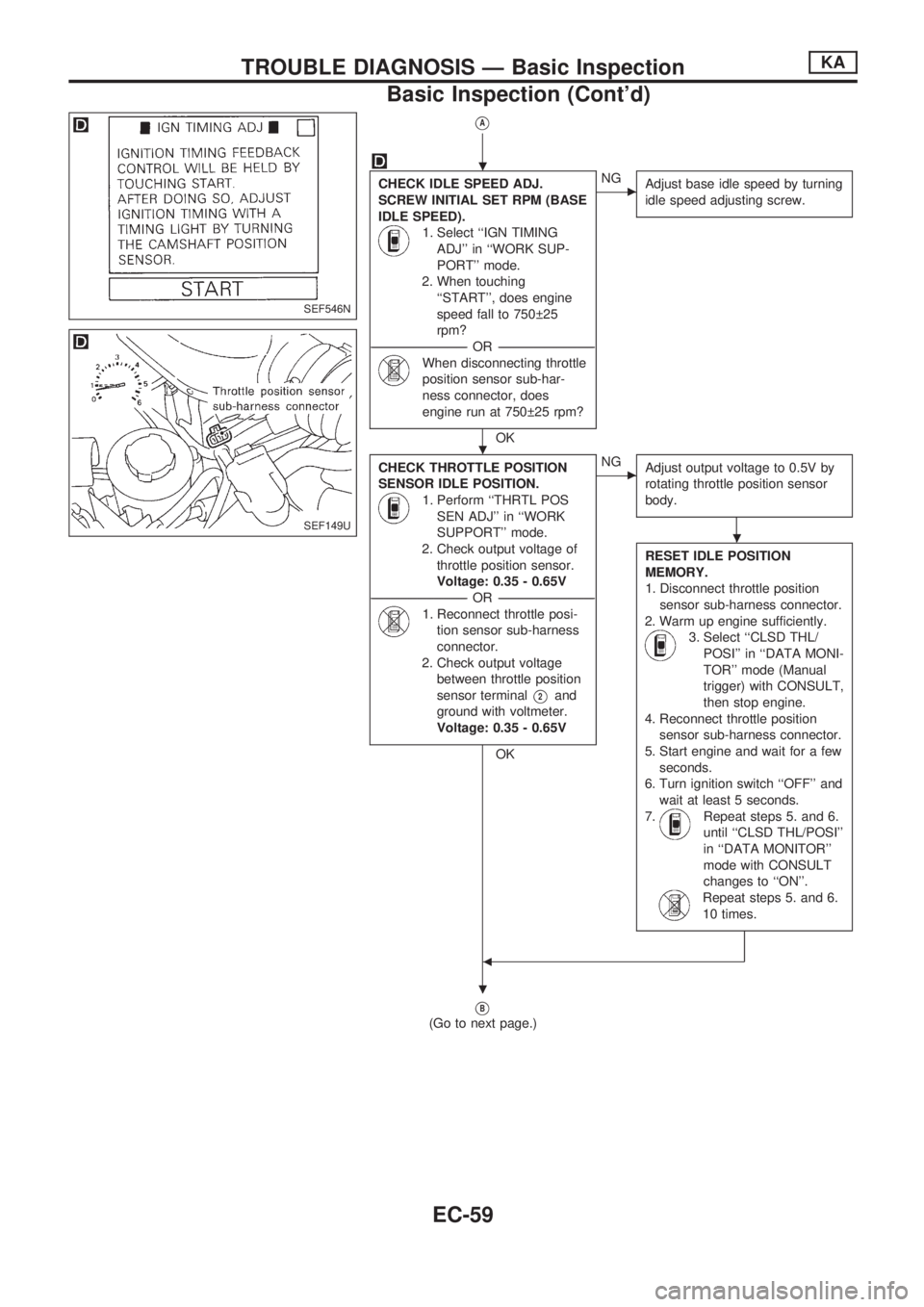
VA
CHECK IDLE SPEED ADJ.
SCREW INITIAL SET RPM (BASE
IDLE SPEED).
1. Select ``IGN TIMING
ADJ'' in ``WORK SUP-
PORT'' mode.
2. When touching
``START'', does engine
speed fall to 750 25
rpm?
-----------------------------------------------------------------------------------------------------------OR -----------------------------------------------------------------------------------------------------------
When disconnecting throttle
position sensor sub-har-
ness connector, does
engine run at 750 25 rpm?
OK
cNG
Adjust base idle speed by turning
idle speed adjusting screw.
CHECK THROTTLE POSITION
SENSOR IDLE POSITION.
1. Perform ``THRTL POS
SEN ADJ'' in ``WORK
SUPPORT'' mode.
2. Check output voltage of
throttle position sensor.
Voltage: 0.35 - 0.65V
-----------------------------------------------------------------------------------------------------------OR -----------------------------------------------------------------------------------------------------------
1. Reconnect throttle posi-
tion sensor sub-harness
connector.
2. Check output voltage
between throttle position
sensor terminal
V2and
ground with voltmeter.
Voltage: 0.35 - 0.65V
OK
cNG
Adjust output voltage to 0.5V by
rotating throttle position sensor
body.
RESET IDLE POSITION
MEMORY.
1. Disconnect throttle position
sensor sub-harness connector.
2. Warm up engine sufficiently.
3. Select ``CLSD THL/
POSI'' in ``DATA MONI-
TOR'' mode (Manual
trigger) with CONSULT,
then stop engine.
4. Reconnect throttle position
sensor sub-harness connector.
5. Start engine and wait for a few
seconds.
6. Turn ignition switch ``OFF'' and
wait at least 5 seconds.
7.
Repeat steps 5. and 6.
until ``CLSD THL/POSI''
in ``DATA MONITOR''
mode with CONSULT
changes to ``ON''.
Repeat steps 5. and 6.
10 times.
b
VB
(Go to next page.)
SEF546N
SEF149U
.
.
.
.
TROUBLE DIAGNOSIS Ð Basic InspectionKA
Basic Inspection (Cont'd)
EC-59
Page 216 of 1659
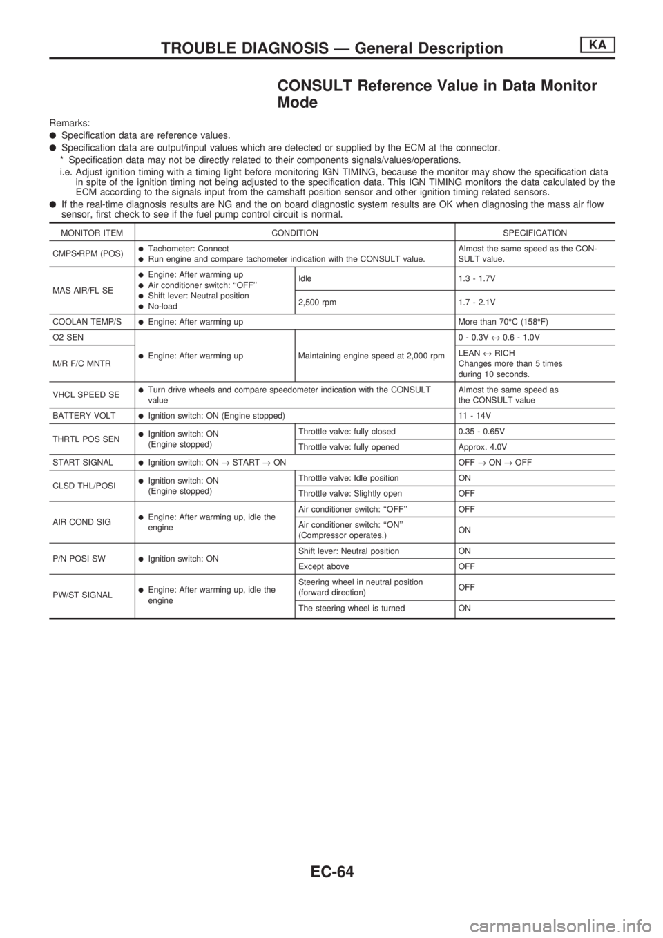
CONSULT Reference Value in Data Monitor
Mode
Remarks:
lSpecification data are reference values.
lSpecification data are output/input values which are detected or supplied by the ECM at the connector.
* Specification data may not be directly related to their components signals/values/operations.
i.e. Adjust ignition timing with a timing light before monitoring IGN TIMING, because the monitor may show the specification data
in spite of the ignition timing not being adjusted to the specification data. This IGN TIMING monitors the data calculated by the
ECM according to the signals input from the camshaft position sensor and other ignition timing related sensors.
lIf the real-time diagnosis results are NG and the on board diagnostic system results are OK when diagnosing the mass air flow
sensor, first check to see if the fuel pump control circuit is normal.
MONITOR ITEM CONDITION SPECIFICATION
CMPScRPM (POS)
lTachometer: ConnectlRun engine and compare tachometer indication with the CONSULT value.Almost the same speed as the CON-
SULT value.
MAS AIR/FL SE
lEngine: After warming uplAir conditioner switch: ``OFF''lShift lever: Neutral positionlNo-loadIdle 1.3 - 1.7V
2,500 rpm 1.7 - 2.1V
COOLAN TEMP/S
lEngine: After warming up More than 70ÉC (158ÉF)
O2 SEN
lEngine: After warming up Maintaining engine speed at 2,000 rpm0 - 0.3V«0.6 - 1.0V
M/R F/C MNTRLEAN«RICH
Changes more than 5 times
during 10 seconds.
VHCL SPEED SE
lTurn drive wheels and compare speedometer indication with the CONSULT
valueAlmost the same speed as
the CONSULT value
BATTERY VOLT
lIgnition switch: ON (Engine stopped) 11 - 14V
THRTL POS SEN
lIgnition switch: ON
(Engine stopped)Throttle valve: fully closed 0.35 - 0.65V
Throttle valve: fully opened Approx. 4.0V
START SIGNAL
lIgnition switch: ON®START®ON OFF®ON®OFF
CLSD THL/POSI
lIgnition switch: ON
(Engine stopped)Throttle valve: Idle position ON
Throttle valve: Slightly open OFF
AIR COND SIG
lEngine: After warming up, idle the
engineAir conditioner switch: ``OFF'' OFF
Air conditioner switch: ``ON''
(Compressor operates.)ON
P/N POSI SW
lIgnition switch: ONShift lever: Neutral position ON
Except above OFF
PW/ST SIGNAL
lEngine: After warming up, idle the
engineSteering wheel in neutral position
(forward direction)OFF
The steering wheel is turned ON
TROUBLE DIAGNOSIS Ð General DescriptionKA
EC-64
Page 247 of 1659
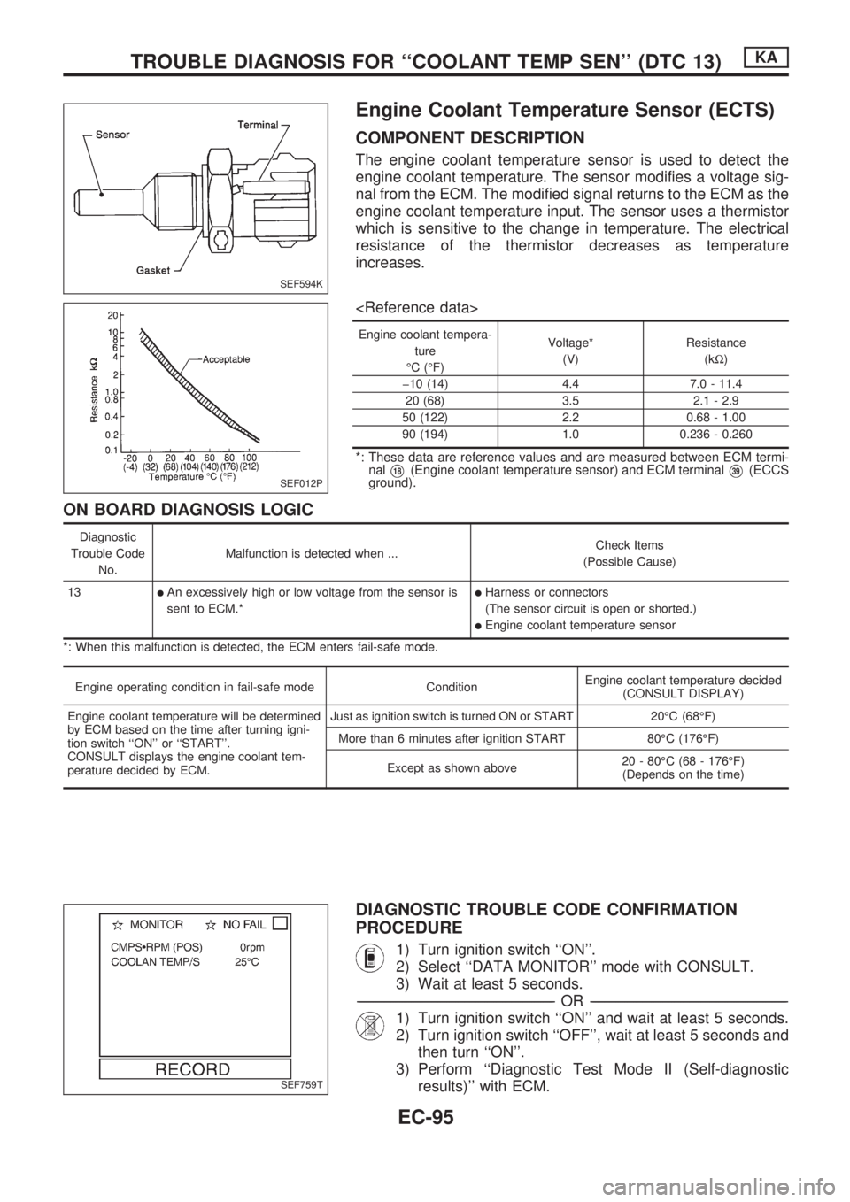
Engine Coolant Temperature Sensor (ECTS)
COMPONENT DESCRIPTION
The engine coolant temperature sensor is used to detect the
engine coolant temperature. The sensor modifies a voltage sig-
nal from the ECM. The modified signal returns to the ECM as the
engine coolant temperature input. The sensor uses a thermistor
which is sensitive to the change in temperature. The electrical
resistance of the thermistor decreases as temperature
increases.
Engine coolant tempera-
ture
ÉC (ÉF)Voltage*
(V)Resistance
(kW)
þ10 (14) 4.4 7.0 - 11.4
20 (68) 3.5 2.1 - 2.9
50 (122) 2.2 0.68 - 1.00
90 (194) 1.0 0.236 - 0.260
*: These data are reference values and are measured between ECM termi-
nal
V18(Engine coolant temperature sensor) and ECM terminalV39(ECCS
ground).
ON BOARD DIAGNOSIS LOGIC
Diagnostic
Trouble Code
No.Malfunction is detected when ...Check Items
(Possible Cause)
13
lAn excessively high or low voltage from the sensor is
sent to ECM.*lHarness or connectors
(The sensor circuit is open or shorted.)
lEngine coolant temperature sensor
*: When this malfunction is detected, the ECM enters fail-safe mode.
Engine operating condition in fail-safe mode ConditionEngine coolant temperature decided
(CONSULT DISPLAY)
Engine coolant temperature will be determined
by ECM based on the time after turning igni-
tion switch ``ON'' or ``START''.
CONSULT displays the engine coolant tem-
perature decided by ECM.Just as ignition switch is turned ON or START 20ÉC (68ÉF)
More than 6 minutes after ignition START 80ÉC (176ÉF)
Except as shown above20 - 80ÉC (68 - 176ÉF)
(Depends on the time)
DIAGNOSTIC TROUBLE CODE CONFIRMATION
PROCEDURE
1) Turn ignition switch ``ON''.
2) Select ``DATA MONITOR'' mode with CONSULT.
3) Wait at least 5 seconds.
-------------------------------------------------------------------------------------------------------------------------------------------------------------------------------------------------------------------------------------------------OR-------------------------------------------------------------------------------------------------------------------------------------------------------------------------------------------------------------------------------------------------
1) Turn ignition switch ``ON'' and wait at least 5 seconds.
2) Turn ignition switch ``OFF'', wait at least 5 seconds and
then turn ``ON''.
3) Perform ``Diagnostic Test Mode II (Self-diagnostic
results)'' with ECM.
SEF594K
SEF012P
SEF759T
TROUBLE DIAGNOSIS FOR ``COOLANT TEMP SEN'' (DTC 13)KA
EC-95
Page 372 of 1659
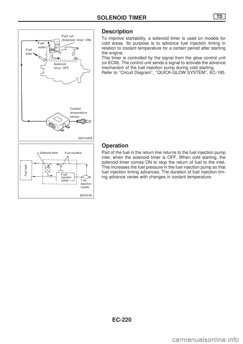
Description
To improve startability, a solenoid timer is used on models for
cold areas. Its purpose is to advance fuel injection timing in
relation to coolant temperature for a certain period after starting
the engine.
This timer is controlled by the signal from the glow control unit
(or ECM). The control unit sends a signal to activate the advance
mechanism of the fuel injection pump during cold starting.
Refer to ``Circuit Diagram'', ``QUICK-GLOW SYSTEM'', EC-195.
Operation
Part of the fuel in the return line returns to the fuel injection pump
inlet, when the solenoid timer is OFF. When cold starting, the
solenoid timer comes ON to stop the return of fuel to the inlet.
This increases the fuel pressure in the fuel injection pump so that
fuel injection timing advances. The duration of fuel injection tim-
ing advance varies with changes in coolant temperature.
SEF419FB
SEF914H
SOLENOID TIMERTD
EC-220