reset NISSAN PICK-UP 1998 Repair Manual
[x] Cancel search | Manufacturer: NISSAN, Model Year: 1998, Model line: PICK-UP, Model: NISSAN PICK-UP 1998Pages: 1659, PDF Size: 53.39 MB
Page 166 of 1659
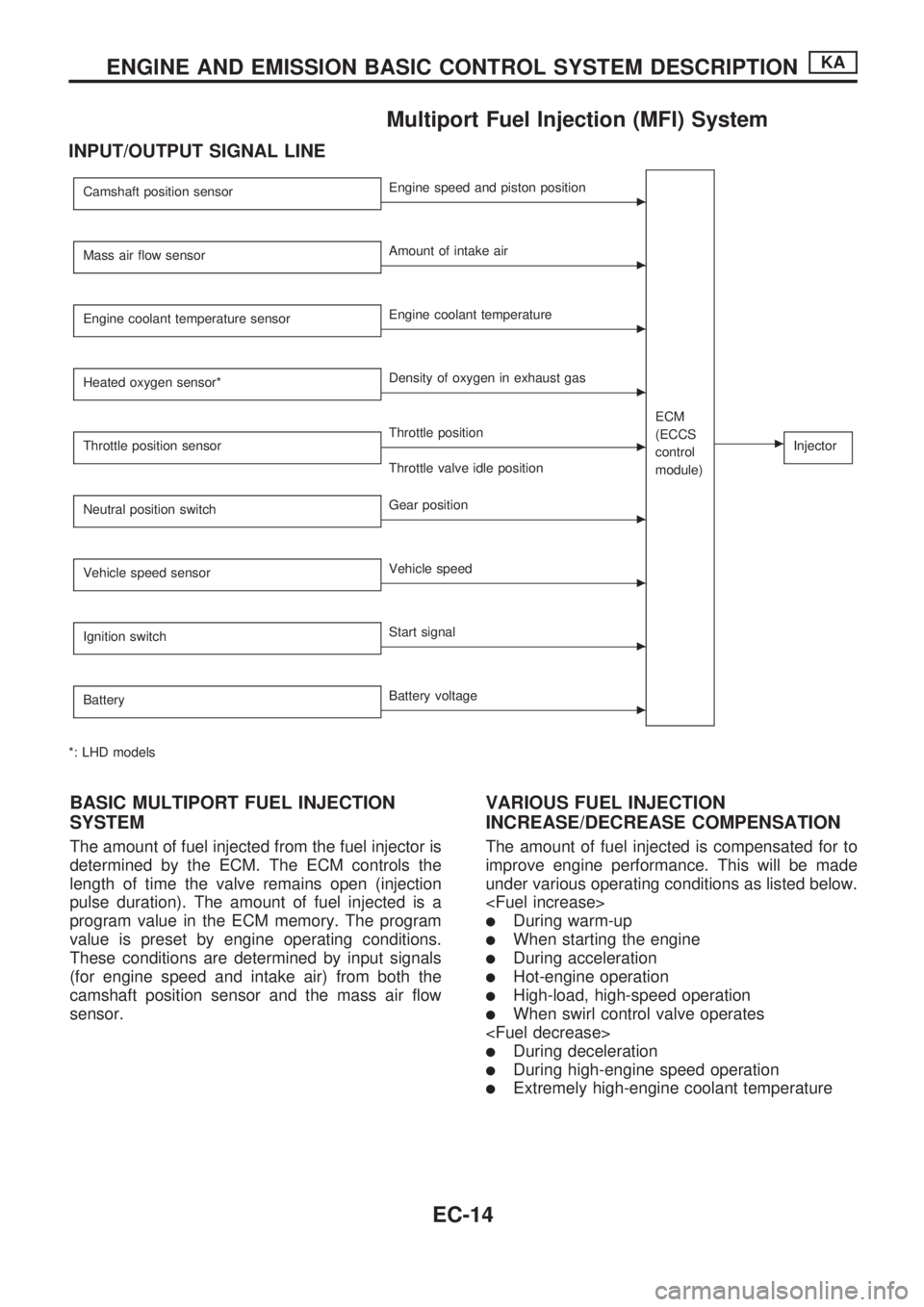
Multiport Fuel Injection (MFI) System
INPUT/OUTPUT SIGNAL LINE
Camshaft position sensorcEngine speed and piston position
ECM
(ECCS
control
module)
cInjector
Mass air flow sensorcAmount of intake air
Engine coolant temperature sensor
cEngine coolant temperature
Heated oxygen sensor*
cDensity of oxygen in exhaust gas
Throttle position sensor
cThrottle position
Throttle valve idle position
Neutral position switch
cGear position
Vehicle speed sensor
cVehicle speed
Ignition switch
cStart signal
Battery
cBattery voltage
*: LHD models
BASIC MULTIPORT FUEL INJECTION
SYSTEM
The amount of fuel injected from the fuel injector is
determined by the ECM. The ECM controls the
length of time the valve remains open (injection
pulse duration). The amount of fuel injected is a
program value in the ECM memory. The program
value is preset by engine operating conditions.
These conditions are determined by input signals
(for engine speed and intake air) from both the
camshaft position sensor and the mass air flow
sensor.
VARIOUS FUEL INJECTION
INCREASE/DECREASE COMPENSATION
The amount of fuel injected is compensated for to
improve engine performance. This will be made
under various operating conditions as listed below.
lDuring warm-up
lWhen starting the engine
lDuring acceleration
lHot-engine operation
lHigh-load, high-speed operation
lWhen swirl control valve operates
lDuring deceleration
lDuring high-engine speed operation
lExtremely high-engine coolant temperature
ENGINE AND EMISSION BASIC CONTROL SYSTEM DESCRIPTIONKA
EC-14
Page 205 of 1659
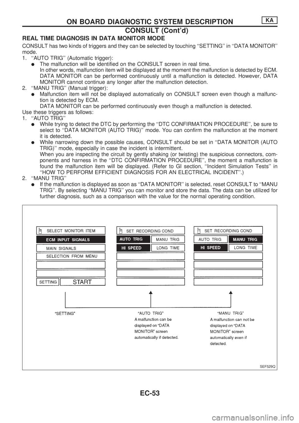
REAL TIME DIAGNOSIS IN DATA MONITOR MODE
CONSULT has two kinds of triggers and they can be selected by touching ``SETTING'' in ``DATA MONITOR''
mode.
1. ``AUTO TRIG'' (Automatic trigger):
lThe malfunction will be identified on the CONSULT screen in real time.
In other words, malfunction item will be displayed at the moment the malfunction is detected by ECM.
DATA MONITOR can be performed continuously until a malfunction is detected. However, DATA
MONITOR cannot continue any longer after the malfunction detection.
2. ``MANU TRIG'' (Manual trigger):
lMalfunction item will not be displayed automatically on CONSULT screen even though a malfunc-
tion is detected by ECM.
DATA MONITOR can be performed continuously even though a malfunction is detected.
Use these triggers as follows:
1. ``AUTO TRIG''
lWhile trying to detect the DTC by performing the ``DTC CONFIRMATION PROCEDURE'', be sure to
select to ``DATA MONITOR (AUTO TRIG)'' mode. You can confirm the malfunction at the moment
it is detected.
lWhile narrowing down the possible causes, CONSULT should be set in ``DATA MONITOR (AUTO
TRIG)'' mode, especially in case the incident is intermittent.
When you are inspecting the circuit by gently shaking (or twisting) the suspicious connectors, com-
ponents and harness in the ``DTC CONFIRMATION PROCEDURE'', the moment a malfunction is
found the malfunction item will be displayed. (Refer to GI section, ``Incident Simulation Tests'' in
``HOW TO PERFORM EFFICIENT DIAGNOSIS FOR AN ELECTRICAL INCIDENT''.)
2. ``MANU TRIG''
lIf the malfunction is displayed as soon as ``DATA MONITOR'' is selected, reset CONSULT to ``MANU
TRIG''. By selecting ``MANU TRIG'' you can monitor and store the data. The data can be utilized for
further diagnosis, such as a comparison with the value for the normal operating condition.
SEF529Q
ON BOARD DIAGNOSTIC SYSTEM DESCRIPTIONKA
CONSULT (Cont'd)
EC-53
Page 211 of 1659
VA
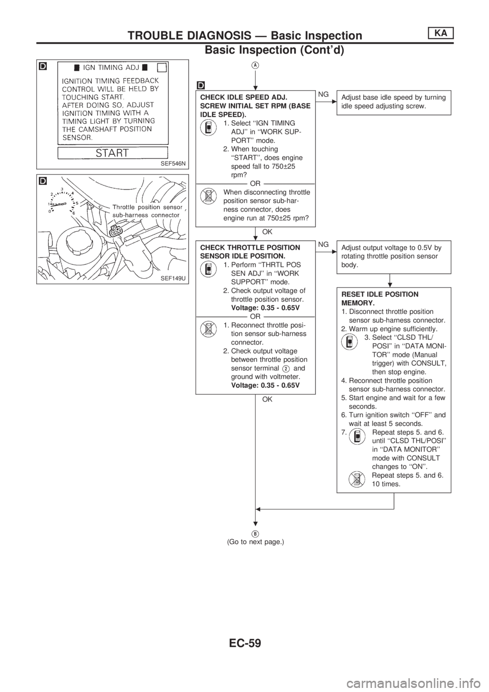
CHECK IDLE SPEED ADJ.
SCREW INITIAL SET RPM (BASE
IDLE SPEED).
1. Select ``IGN TIMING
ADJ'' in ``WORK SUP-
PORT'' mode.
2. When touching
``START'', does engine
speed fall to 750 25
rpm?
-----------------------------------------------------------------------------------------------------------OR -----------------------------------------------------------------------------------------------------------
When disconnecting throttle
position sensor sub-har-
ness connector, does
engine run at 750 25 rpm?
OK
cNG
Adjust base idle speed by turning
idle speed adjusting screw.
CHECK THROTTLE POSITION
SENSOR IDLE POSITION.
1. Perform ``THRTL POS
SEN ADJ'' in ``WORK
SUPPORT'' mode.
2. Check output voltage of
throttle position sensor.
Voltage: 0.35 - 0.65V
-----------------------------------------------------------------------------------------------------------OR -----------------------------------------------------------------------------------------------------------
1. Reconnect throttle posi-
tion sensor sub-harness
connector.
2. Check output voltage
between throttle position
sensor terminal
V2and
ground with voltmeter.
Voltage: 0.35 - 0.65V
OK
cNG
Adjust output voltage to 0.5V by
rotating throttle position sensor
body.
RESET IDLE POSITION
MEMORY.
1. Disconnect throttle position
sensor sub-harness connector.
2. Warm up engine sufficiently.
3. Select ``CLSD THL/
POSI'' in ``DATA MONI-
TOR'' mode (Manual
trigger) with CONSULT,
then stop engine.
4. Reconnect throttle position
sensor sub-harness connector.
5. Start engine and wait for a few
seconds.
6. Turn ignition switch ``OFF'' and
wait at least 5 seconds.
7.
Repeat steps 5. and 6.
until ``CLSD THL/POSI''
in ``DATA MONITOR''
mode with CONSULT
changes to ``ON''.
Repeat steps 5. and 6.
10 times.
b
VB
(Go to next page.)
SEF546N
SEF149U
.
.
.
.
TROUBLE DIAGNOSIS Ð Basic InspectionKA
Basic Inspection (Cont'd)
EC-59
Page 213 of 1659
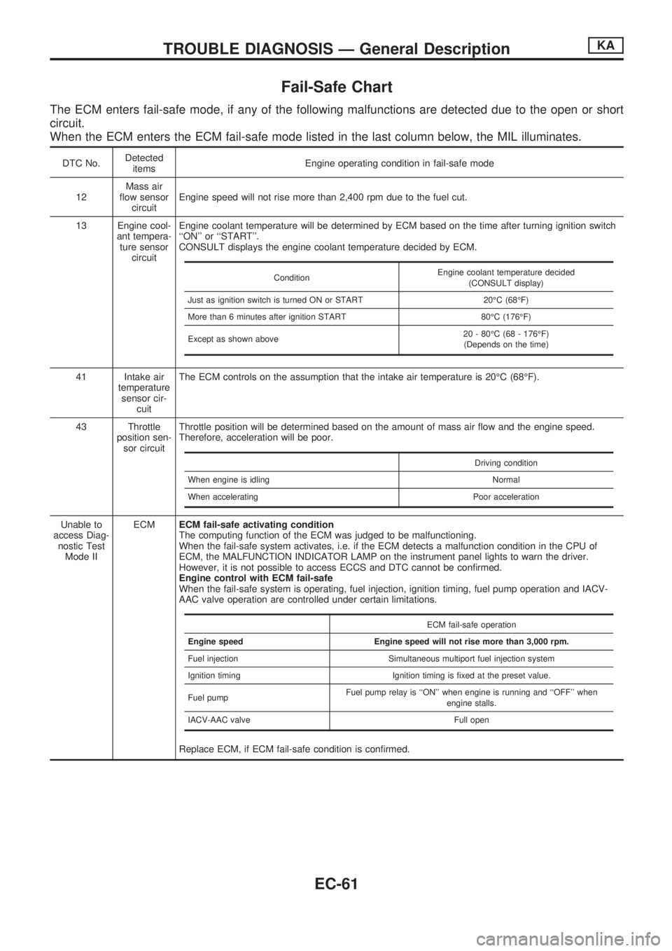
Fail-Safe Chart
The ECM enters fail-safe mode, if any of the following malfunctions are detected due to the open or short
circuit.
When the ECM enters the ECM fail-safe mode listed in the last column below, the MIL illuminates.
DTC No.Detected
itemsEngine operating condition in fail-safe mode
12Mass air
flow sensor
circuitEngine speed will not rise more than 2,400 rpm due to the fuel cut.
13 Engine cool-
ant tempera-
ture sensor
circuitEngine coolant temperature will be determined by ECM based on the time after turning ignition switch
``ON'' or ``START''.
CONSULT displays the engine coolant temperature decided by ECM.
41 Intake air
temperature
sensor cir-
cuitThe ECM controls on the assumption that the intake air temperature is 20ÉC (68ÉF).
43 Throttle
position sen-
sor circuitThrottle position will be determined based on the amount of mass air flow and the engine speed.
Therefore, acceleration will be poor.
Unable to
access Diag-
nostic Test
Mode IIECMECM fail-safe activating condition
The computing function of the ECM was judged to be malfunctioning.
When the fail-safe system activates, i.e. if the ECM detects a malfunction condition in the CPU of
ECM, the MALFUNCTION INDICATOR LAMP on the instrument panel lights to warn the driver.
However, it is not possible to access ECCS and DTC cannot be confirmed.
Engine control with ECM fail-safe
When the fail-safe system is operating, fuel injection, ignition timing, fuel pump operation and IACV-
AAC valve operation are controlled under certain limitations.
Replace ECM, if ECM fail-safe condition is confirmed.
ConditionEngine coolant temperature decided
(CONSULT display)
Just as ignition switch is turned ON or START 20ÉC (68ÉF)
More than 6 minutes after ignition START 80ÉC (176ÉF)
Except as shown above20 - 80ÉC (68 - 176ÉF)
(Depends on the time)
Driving condition
When engine is idling Normal
When accelerating Poor acceleration
ECM fail-safe operation
Engine speed Engine speed will not rise more than 3,000 rpm.
Fuel injection Simultaneous multiport fuel injection system
Ignition timing Ignition timing is fixed at the preset value.
Fuel pumpFuel pump relay is ``ON'' when engine is running and ``OFF'' when
engine stalls.
IACV-AAC valve Full open
TROUBLE DIAGNOSIS Ð General DescriptionKA
EC-61
Page 322 of 1659
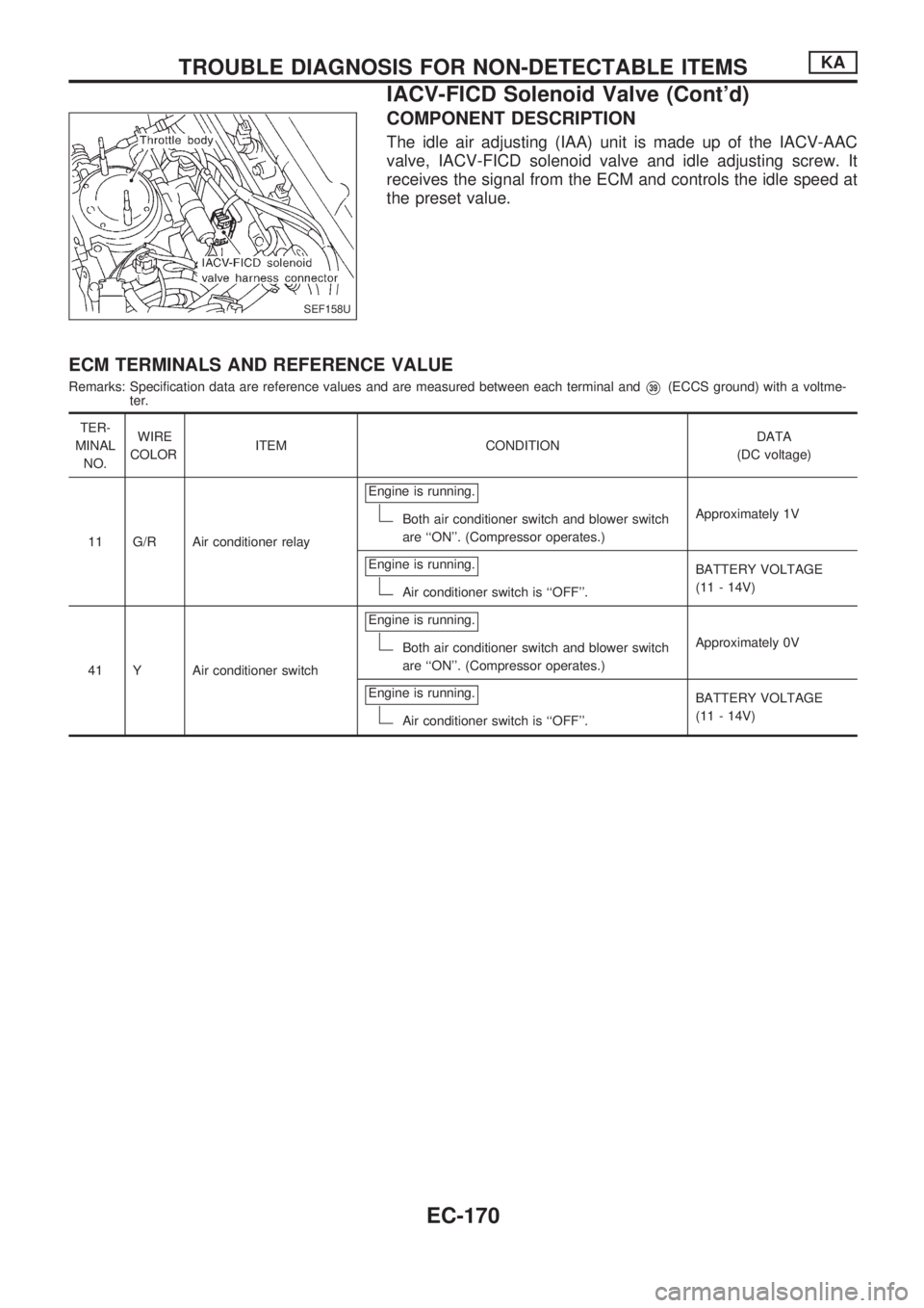
COMPONENT DESCRIPTION
The idle air adjusting (IAA) unit is made up of the IACV-AAC
valve, IACV-FICD solenoid valve and idle adjusting screw. It
receives the signal from the ECM and controls the idle speed at
the preset value.
ECM TERMINALS AND REFERENCE VALUE
Remarks: Specification data are reference values and are measured between each terminal andV39(ECCS ground) with a voltme-
ter.
TER-
MINAL
NO.WIRE
COLORITEM CONDITIONDATA
(DC voltage)
11 G/R Air conditioner relayEngine is running.
Both air conditioner switch and blower switch
are ``ON''. (Compressor operates.)Approximately 1V
Engine is running.
Air conditioner switch is ``OFF''.BATTERY VOLTAGE
(11 - 14V)
41 Y Air conditioner switchEngine is running.
Both air conditioner switch and blower switch
are ``ON''. (Compressor operates.)Approximately 0V
Engine is running.
Air conditioner switch is ``OFF''.BATTERY VOLTAGE
(11 - 14V)
SEF158U
TROUBLE DIAGNOSIS FOR NON-DETECTABLE ITEMSKA
IACV-FICD Solenoid Valve (Cont'd)
EC-170
Page 532 of 1659
Trouble Diagnoses
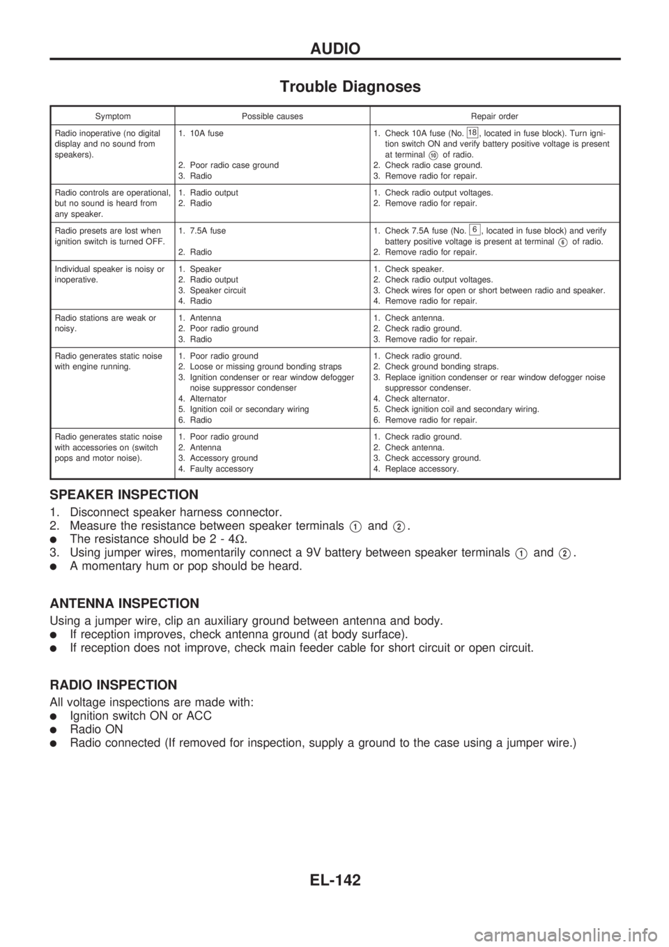
Symptom Possible causes Repair order
Radio inoperative (no digital
display and no sound from
speakers).1. 10A fuse
2. Poor radio case ground
3. Radio1. Check 10A fuse (No.
18, located in fuse block). Turn igni-
tion switch ON and verify battery positive voltage is present
at terminal
V10of radio.
2. Check radio case ground.
3. Remove radio for repair.
Radio controls are operational,
but no sound is heard from
any speaker.1. Radio output
2. Radio1. Check radio output voltages.
2. Remove radio for repair.
Radio presets are lost when
ignition switch is turned OFF.1. 7.5A fuse
2. Radio1. Check 7.5A fuse (No.
6, located in fuse block) and verify
battery positive voltage is present at terminal
V6of radio.
2. Remove radio for repair.
Individual speaker is noisy or
inoperative.1. Speaker
2. Radio output
3. Speaker circuit
4. Radio1. Check speaker.
2. Check radio output voltages.
3. Check wires for open or short between radio and speaker.
4. Remove radio for repair.
Radio stations are weak or
noisy.1. Antenna
2. Poor radio ground
3. Radio1. Check antenna.
2. Check radio ground.
3. Remove radio for repair.
Radio generates static noise
with engine running.1. Poor radio ground
2. Loose or missing ground bonding straps
3. Ignition condenser or rear window defogger
noise suppressor condenser
4. Alternator
5. Ignition coil or secondary wiring
6. Radio1. Check radio ground.
2. Check ground bonding straps.
3. Replace ignition condenser or rear window defogger noise
suppressor condenser.
4. Check alternator.
5. Check ignition coil and secondary wiring.
6. Remove radio for repair.
Radio generates static noise
with accessories on (switch
pops and motor noise).1. Poor radio ground
2. Antenna
3. Accessory ground
4. Faulty accessory1. Check radio ground.
2. Check antenna.
3. Check accessory ground.
4. Replace accessory.
SPEAKER INSPECTION
1. Disconnect speaker harness connector.
2. Measure the resistance between speaker terminals
V1andV2.
lThe resistance should be2-4W.
3. Using jumper wires, momentarily connect a 9V battery between speaker terminals
V1andV2.
lA momentary hum or pop should be heard.
ANTENNA INSPECTION
Using a jumper wire, clip an auxiliary ground between antenna and body.
lIf reception improves, check antenna ground (at body surface).
lIf reception does not improve, check main feeder cable for short circuit or open circuit.
RADIO INSPECTION
All voltage inspections are made with:
lIgnition switch ON or ACC
lRadio ON
lRadio connected (If removed for inspection, supply a ground to the case using a jumper wire.)
AUDIO
EL-142
Page 533 of 1659
CATS (Code) System/For Europe RHD
NOTE:
lThis system is used for code indicator-equipped radios on all models.
lThe Europe LHD model with KA24E engine has a NATS-linked anti-theft function with radio as
optional equipment that renders the code system inoperable.
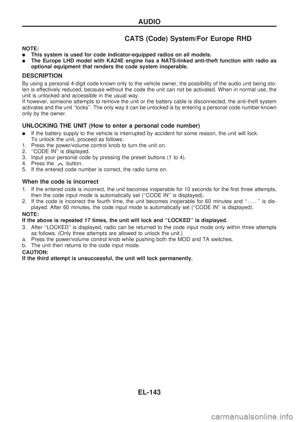
DESCRIPTION
By using a personal 4-digit code known only to the vehicle owner, the possibility of the audio unit being sto-
len is effectively reduced, because without the code the unit can not be activated. When in normal use, the
unit is unlocked and accessible in the usual way.
If however, someone attempts to remove the unit or the battery cable is disconnected, the anti-theft system
activates and the unit ``locks''. The only way it can be unlocked is by entering a personal code number known
only by the owner.
UNLOCKING THE UNIT (How to enter a personal code number)
lIf the battery supply to the vehicle is interrupted by accident for some reason, the unit will lock.
To unlock the unit, proceed as follows:
1. Press the power/volume control knob to turn the unit on.
2. ``CODE IN'' is displayed.
3. Input your personal code by pressing the preset buttons (1 to 4).
4. Press the
button.
5. If the entered code number is correct, the radio turns on.
When the code is incorrect
1. If the entered code is incorrect, the unit becomes inoperable for 10 seconds for the first three attempts,
then the code input mode is automatically set (``CODE IN'' is displayed).
2. If the code is incorrect the fourth time, the unit becomes inoperable for 60 minutes and ``
'' is dis-
played. After 60 minutes, the code input mode is automatically set (``CODE IN'' is displayed).
NOTE:
If the above is repeated 17 times, the unit will lock and ``LOCKED'' is displayed.
3. After ``LOCKED'' is displayed, radio can be returned to the code input mode only within three attempts
as follows. (Only three attempts are allowed to unlock the unit.)
a. Press the power/volume control knob while pushing both the MOD and TA switches.
b. The unit then returns to the code input mode.
CAUTION:
If the third attempt is unsuccessful, the unit will lock permanently.
AUDIO
EL-143
Page 534 of 1659
NATS Audio Link/For Europe LHD (KA24E)
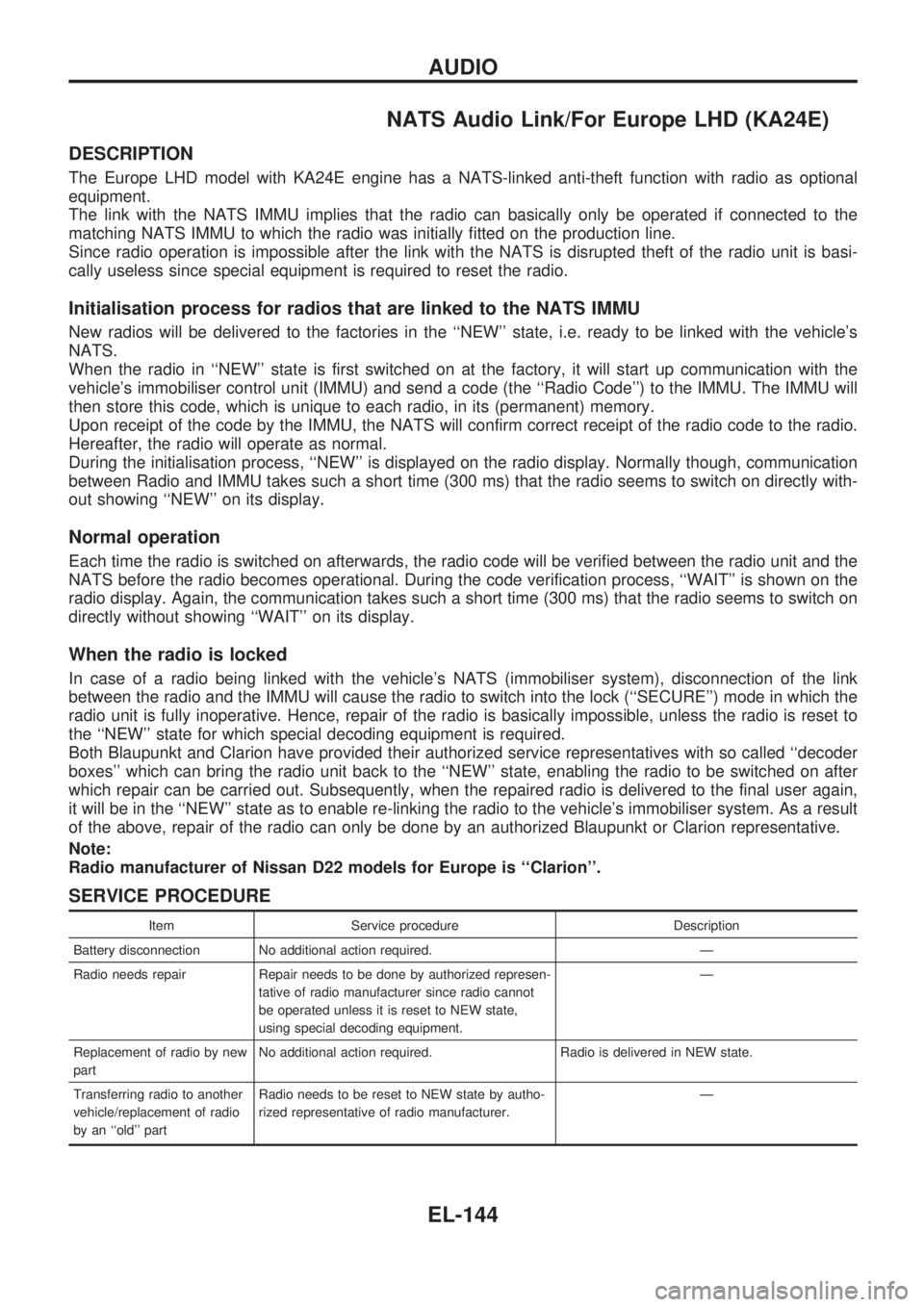
DESCRIPTION
The Europe LHD model with KA24E engine has a NATS-linked anti-theft function with radio as optional
equipment.
The link with the NATS IMMU implies that the radio can basically only be operated if connected to the
matching NATS IMMU to which the radio was initially fitted on the production line.
Since radio operation is impossible after the link with the NATS is disrupted theft of the radio unit is basi-
cally useless since special equipment is required to reset the radio.
Initialisation process for radios that are linked to the NATS IMMU
New radios will be delivered to the factories in the ``NEW'' state, i.e. ready to be linked with the vehicle's
NATS.
When the radio in ``NEW'' state is first switched on at the factory, it will start up communication with the
vehicle's immobiliser control unit (IMMU) and send a code (the ``Radio Code'') to the IMMU. The IMMU will
then store this code, which is unique to each radio, in its (permanent) memory.
Upon receipt of the code by the IMMU, the NATS will confirm correct receipt of the radio code to the radio.
Hereafter, the radio will operate as normal.
During the initialisation process, ``NEW'' is displayed on the radio display. Normally though, communication
between Radio and IMMU takes such a short time (300 ms) that the radio seems to switch on directly with-
out showing ``NEW'' on its display.
Normal operation
Each time the radio is switched on afterwards, the radio code will be verified between the radio unit and the
NATS before the radio becomes operational. During the code verification process, ``WAIT'' is shown on the
radio display. Again, the communication takes such a short time (300 ms) that the radio seems to switch on
directly without showing ``WAIT'' on its display.
When the radio is locked
In case of a radio being linked with the vehicle's NATS (immobiliser system), disconnection of the link
between the radio and the IMMU will cause the radio to switch into the lock (``SECURE'') mode in which the
radio unit is fully inoperative. Hence, repair of the radio is basically impossible, unless the radio is reset to
the ``NEW'' state for which special decoding equipment is required.
Both Blaupunkt and Clarion have provided their authorized service representatives with so called ``decoder
boxes'' which can bring the radio unit back to the ``NEW'' state, enabling the radio to be switched on after
which repair can be carried out. Subsequently, when the repaired radio is delivered to the final user again,
it will be in the ``NEW'' state as to enable re-linking the radio to the vehicle's immobiliser system. As a result
of the above, repair of the radio can only be done by an authorized Blaupunkt or Clarion representative.
Note:
Radio manufacturer of Nissan D22 models for Europe is ``Clarion''.
SERVICE PROCEDURE
Item Service procedure Description
Battery disconnection No additional action required. Ð
Radio needs repair Repair needs to be done by authorized represen-
tative of radio manufacturer since radio cannot
be operated unless it is reset to NEW state,
using special decoding equipment.Ð
Replacement of radio by new
partNo additional action required. Radio is delivered in NEW state.
Transferring radio to another
vehicle/replacement of radio
by an ``old'' partRadio needs to be reset to NEW state by autho-
rized representative of radio manufacturer.Ð
AUDIO
EL-144
Page 535 of 1659
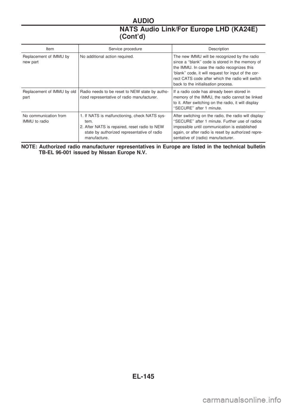
Item Service procedure Description
Replacement of IMMU by
new partNo additional action required. The new IMMU will be recognized by the radio
since a ``blank'' code is stored in the memory of
the IMMU. In case the radio recognizes this
`blank'' code, it will request for input of the cor-
rect CATS code after which the radio will switch
back to the initialisation process.
Replacement of IMMU by old
partRadio needs to be reset to NEW state by autho-
rized representative of radio manufacturer.If a radio code has already been stored in
memory of the IMMU, the radio cannot be linked
to it. After switching on the radio, it will display
``SECURE'' after 1 minute.
No communication from
IMMU to radio1. If NATS is malfunctioning, check NATS sys-
tem.
2. After NATS is repaired, reset radio to NEW
state by authorized representative of radio
manufacture.After switching on the radio, the radio will display
``SECURE'' after 1 minute. Further use of radios
impossible until communication is established
again, or after radio is reset by authorized repre-
sentative of (radio) manufacturer.
NOTE: Authorized radio manufacturer representatives in Europe are listed in the technical bulletin
TB-EL 96-001 issued by Nissan Europe N.V.
AUDIO
NATS Audio Link/For Europe LHD (KA24E)
(Cont'd)
EL-145
Page 1185 of 1659
Trouble Diagnoses Introduction
CAUTION:
lDo not use a circuit tester to check SRS harness connectors unless instructed to in this Service
Manual. SRS wiring harnesses can be identified with yellow harness protector or yellow insula-
tion tape before the harness connectors.
lDo not attempt to repair, splice or modify the SRS wiring harness. If the harness is damaged,
replace it with a new one.
lKeep ground portion clean.
DIAGNOSIS FUNCTION
The SRS self-diagnosis results can be read by using ``AIR BAG'' warning lamp and/or CONSULT. The
reading of these results is accomplished using one of two modes Ð ``User mode'' and ``Diagnosis mode''.
The User mode is exclusively prepared for the customer (driver). This mode warns the driver of a system
malfunction through the operation of the ``AIR BAG'' warning lamp.
The Diagnosis mode allows the technician to locate and inspect the malfunctioning part.
The mode applications for the ``AIR BAG'' warning lamp and CONSULT are as follows:
User mode Diagnosis mode Display type
``AIR BAG'' warning lamp X X ON-OFF operation
CONSULT Ð X Monitoring
DIAGNOSIS MODE FOR CONSULT
l``SELF-DIAG [CURRENT]''
A current Self-diagnosis result (also indicated by the warning lamp flashes in the Diagnosis mode) is
displayed on the CONSULT screen in real time. This refers to a malfunctioning part requiring repairs.
l``SELF-DIAG [PAST]''
Diagnosis results previously stored in the memory (also indicated by the warning lamp flashes in the
Diagnosis mode) are displayed on the CONSULT screen. The stored results are not erased until memory
erasing is executed.
l``TROUBLE DIAG RECORD''
With TROUBLE DIAG RECORD, diagnosis results previously erased by a reset operation can be dis-
played on the CONSULT screen.
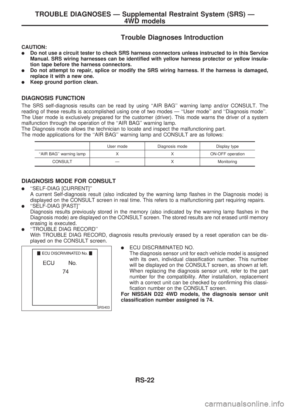
lECU DISCRIMINATED NO.
The diagnosis sensor unit for each vehicle model is assigned
with its own, individual classification number. This number
will be displayed on the CONSULT screen, as shown at left.
When replacing the diagnosis sensor unit, refer to the part
number for the compatibility. After installation, replacement
with a correct unit can be checked by confirming this classi-
fication number on the CONSULT screen.
For NISSAN D22 4WD models, the diagnosis sensor unit
classification number assigned is 74.
SRS403
TROUBLE DIAGNOSES Ð Supplemental Restraint System (SRS) Ð
4WD models
RS-22