combination lamp NISSAN PICK-UP 1998 Repair Manual
[x] Cancel search | Manufacturer: NISSAN, Model Year: 1998, Model line: PICK-UP, Model: NISSAN PICK-UP 1998Pages: 1659, PDF Size: 53.39 MB
Page 79 of 1659
Note: ABS may operate and cause vibration under any of the
following conditions.
lApplying brake gradually when shifting or operating
clutch.
lLow friction (slippery) road.
lHigh speed cornering.
lDriving over bumps and pot holes.
lEngine speed is over 5,000 rpm with vehicle stopped.
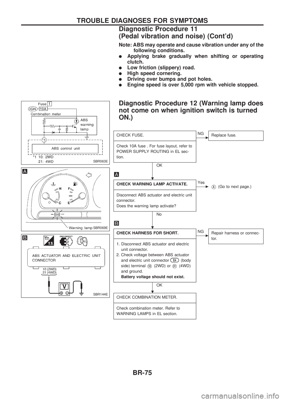
Diagnostic Procedure 12 (Warning lamp does
not come on when ignition switch is turned
ON.)
CHECK FUSE.
-------------------------------------------------------------------------------------------------------------------------------------------------------------------------------------------------------------------------------------------------------------------------------------------------------------
Check 10A fuse . For fuse layout, refer to
POWER SUPPLY ROUTING in EL sec-
tion.
OK
cNG
Replace fuse.
CHECK WARNING LAMP ACTIVATE.
-------------------------------------------------------------------------------------------------------------------------------------------------------------------------------------------------------------------------------------------------------------------------------------------------------------
Disconnect ABS actuator and electric unit
connector.
Does the warning lamp activate?
No
cYes
VA(Go to next page.)
CHECK HARNESS FOR SHORT.
-------------------------------------------------------------------------------------------------------------------------------------------------------------------------------------------------------------------------------------------------------------------------------------------------------------
1. Disconnect ABS actuator and electric
unit connector.
2. Check voltage between ABS actuator
and electric unit connector
E4(body
side) terminal
V10(2WD) orV21(4WD)
and ground.
Battery voltage should not exist.
OK
cNG
Repair harness or connec-
tor.
CHECK COMBINATION METER.
-------------------------------------------------------------------------------------------------------------------------------------------------------------------------------------------------------------------------------------------------------------------------------------------------------------
Check combination meter. Refer to
WARNING LAMPS in EL section.
SBR063E
SBR069E
SBR144E
.
.
.
TROUBLE DIAGNOSES FOR SYMPTOMS
Diagnostic Procedure 11
(Pedal vibration and noise) (Cont'd)
BR-75
Page 81 of 1659
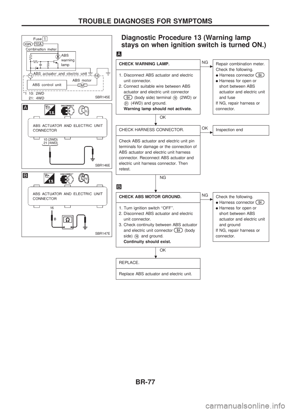
Diagnostic Procedure 13 (Warning lamp
stays on when ignition switch is turned ON.)
CHECK WARNING LAMP.
-------------------------------------------------------------------------------------------------------------------------------------------------------------------------------------------------------------------------------------------------------------------------------------------------------------
1. Disconnect ABS actuator and electric
unit connector.
2. Connect suitable wire between ABS
actuator and electric unit connector
E4(body side) terminalV10(2WD) or
V21(4WD) and ground.
Warning lamp should not activate.
OK
cNG
Repair combination meter.
Check the following.
lHarness connectorE4
lHarness for open or
short between ABS
actuator and electric unit
and fuse
If NG, repair harness or
connector.
CHECK HARNESS CONNECTOR.
-------------------------------------------------------------------------------------------------------------------------------------------------------------------------------------------------------------------------------------------------------------------------------------------------------------
Check ABS actuator and electric unit pin
terminals for damage or the connection of
ABS actuator and electric unit harness
connector. Reconnect ABS actuator and
electric unit harness connector. Then
retest.
NG
cOK
Inspection end
CHECK ABS MOTOR GROUND.
-------------------------------------------------------------------------------------------------------------------------------------------------------------------------------------------------------------------------------------------------------------------------------------------------------------
1. Turn ignition switch ``OFF''.
2. Disconnect ABS actuator and electric
unit connector.
3. Check continuity between ABS actuator
and electric unit connector
E4(body
side)
V16and ground.
Continuity should exist.
OK
cNG
Check the following.
lHarness connectorE4
lHarness for open or
short between ABS
actuator and electric unit
and ground
If NG, repair harness or
connector.
REPLACE.
-------------------------------------------------------------------------------------------------------------------------------------------------------------------------------------------------------------------------------------------------------------------------------------------------------------
Replace ABS actuator and electric unit.
SBR145E
SBR146E
SBR147E
.
.
.
TROUBLE DIAGNOSES FOR SYMPTOMS
BR-77
Page 105 of 1659
Body Front End
lWhen removing or installing hood, place a cloth or other padding on hood. This prevents vehicle body
from being scratched.
lBumper fascia is made of plastic. Do not use excessive force and be sure to keep oil away from it.
lHood adjustment: Adjust at hinge portion.
lHood lock adjustment: After adjusting, check hood lock control operation. Apply a coat of grease to hood
locks engaging mechanism.
lHood opener: Do not attempt to bend cable forcibly. Doing so increases effort required to unlock hood.
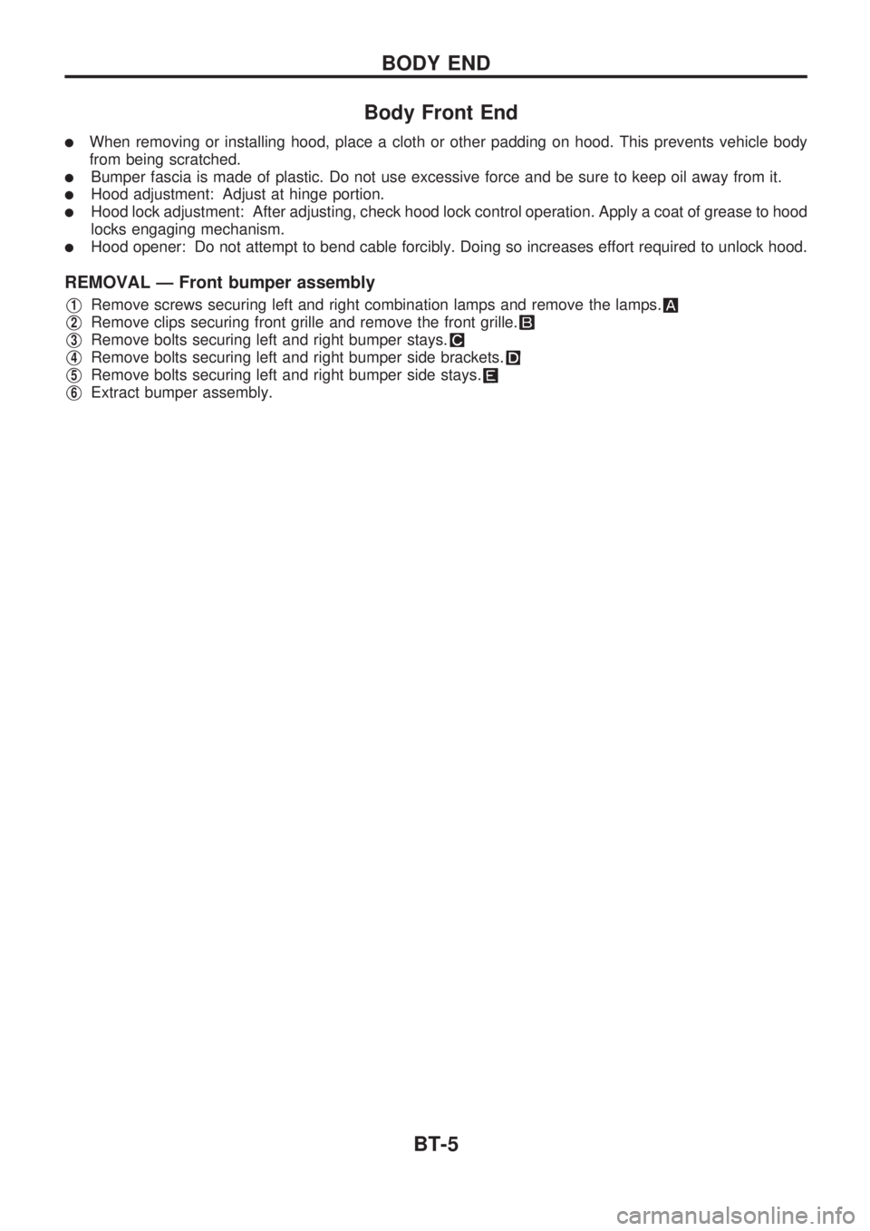
REMOVAL Ð Front bumper assembly
V1Remove screws securing left and right combination lamps and remove the lamps.
V2Remove clips securing front grille and remove the front grille.
V3Remove bolts securing left and right bumper stays.
V4Remove bolts securing left and right bumper side brackets.
V5Remove bolts securing left and right bumper side stays.
V6Extract bumper assembly.
BODY END
BT-5
Page 127 of 1659

V10Back windowV11Drafter duct
V12Over fender
V13Rear combination lamp
Mounted with bolts.
SBT450SBT455
SBT451
EXTERIOR
BT-27
Page 140 of 1659
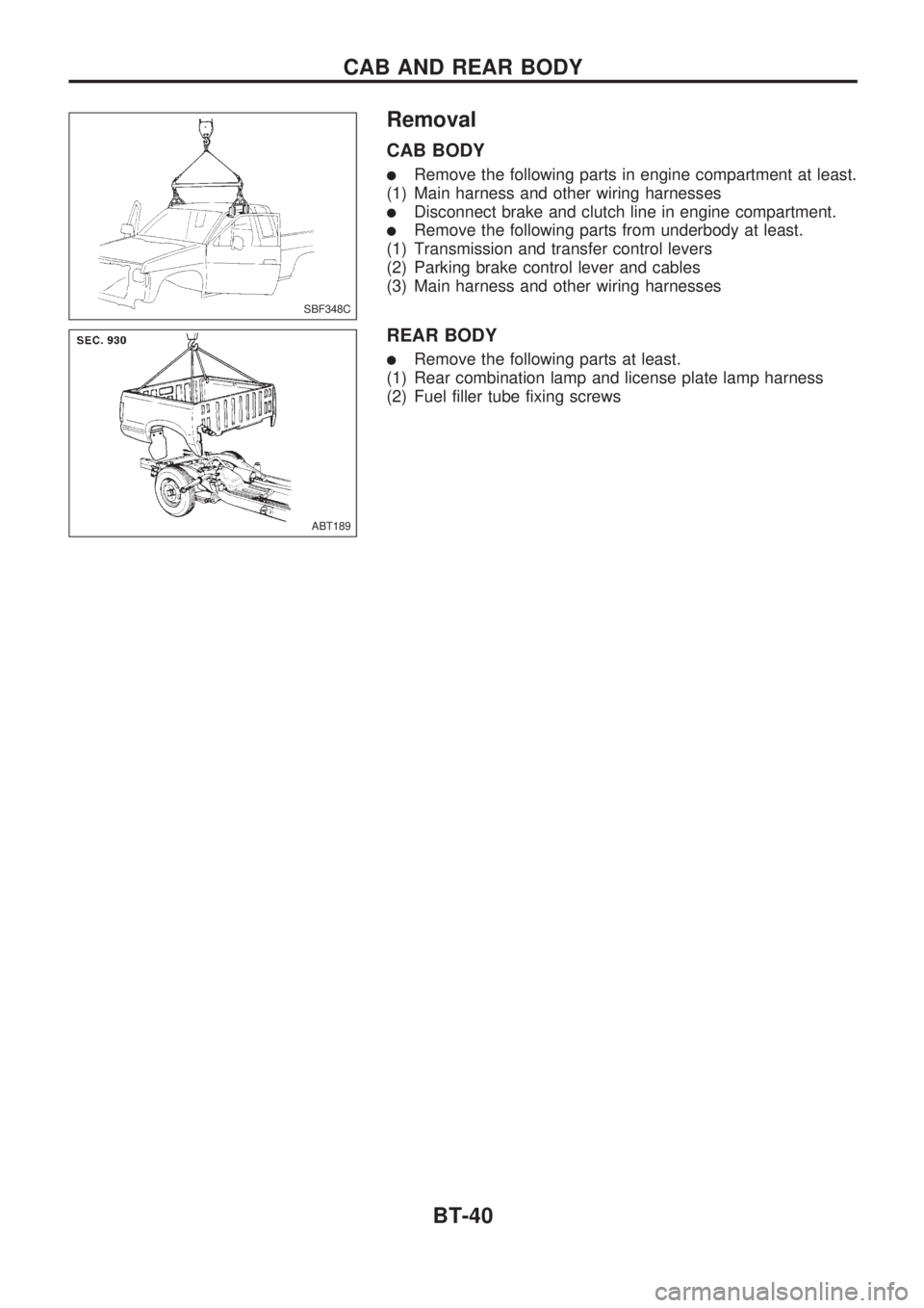
Removal
CAB BODY
lRemove the following parts in engine compartment at least.
(1) Main harness and other wiring harnesses
lDisconnect brake and clutch line in engine compartment.
lRemove the following parts from underbody at least.
(1) Transmission and transfer control levers
(2) Parking brake control lever and cables
(3) Main harness and other wiring harnesses
REAR BODY
lRemove the following parts at least.
(1) Rear combination lamp and license plate lamp harness
(2) Fuel filler tube fixing screws
SBF348C
ABT189
CAB AND REAR BODY
BT-40
Page 388 of 1659
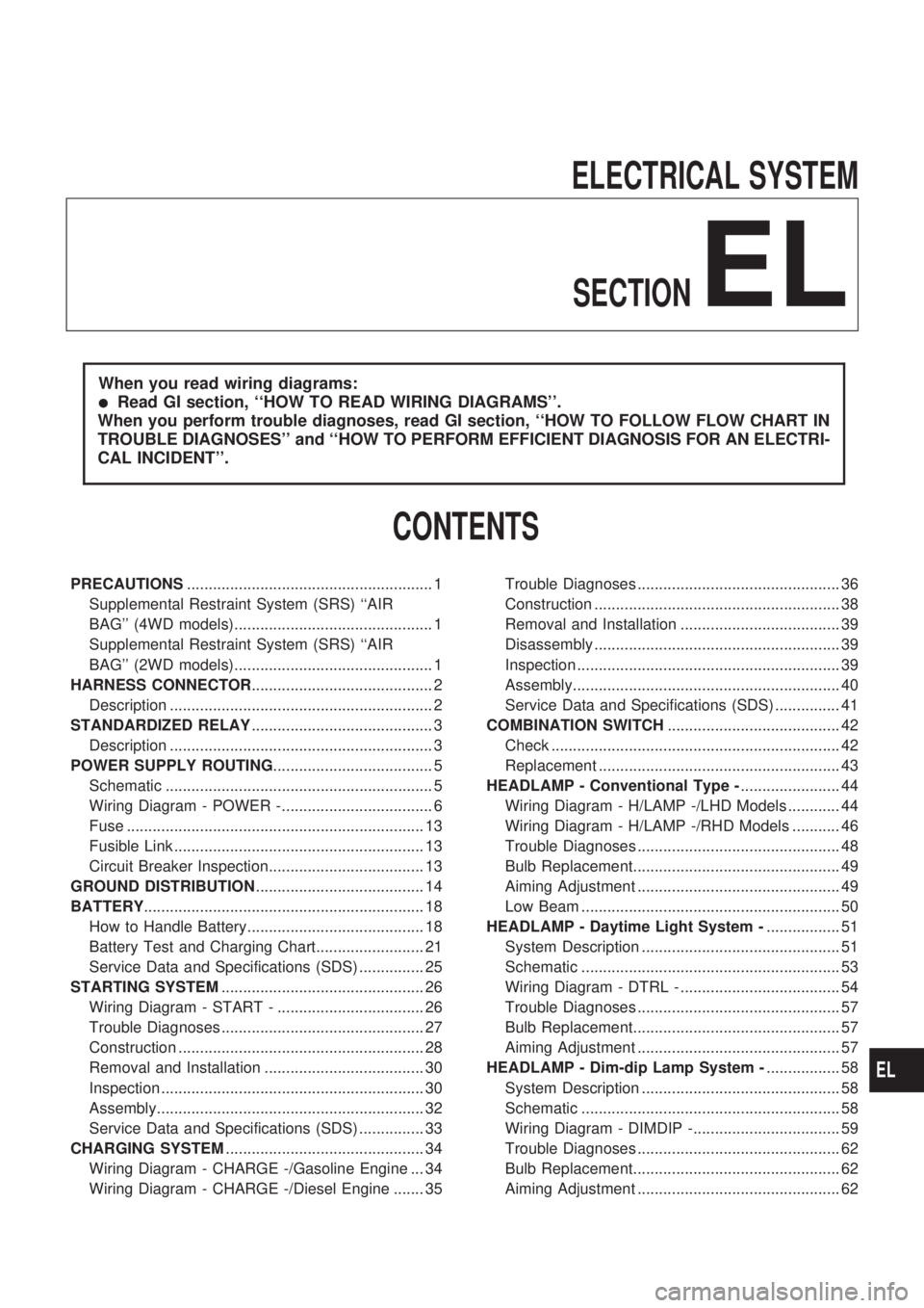
ELECTRICAL SYSTEM
SECTION
EL
When you read wiring diagrams:
lRead GI section, ``HOW TO READ WIRING DIAGRAMS''.
When you perform trouble diagnoses, read GI section, ``HOW TO FOLLOW FLOW CHART IN
TROUBLE DIAGNOSES'' and ``HOW TO PERFORM EFFICIENT DIAGNOSIS FOR AN ELECTRI-
CAL INCIDENT''.
CONTENTS
PRECAUTIONS......................................................... 1
Supplemental Restraint System (SRS) ``AIR
BAG'' (4WD models).............................................. 1
Supplemental Restraint System (SRS) ``AIR
BAG'' (2WD models).............................................. 1
HARNESS CONNECTOR.......................................... 2
Description ............................................................. 2
STANDARDIZED RELAY.......................................... 3
Description ............................................................. 3
POWER SUPPLY ROUTING..................................... 5
Schematic .............................................................. 5
Wiring Diagram - POWER -................................... 6
Fuse ..................................................................... 13
Fusible Link .......................................................... 13
Circuit Breaker Inspection.................................... 13
GROUND DISTRIBUTION....................................... 14
BATTERY................................................................. 18
How to Handle Battery......................................... 18
Battery Test and Charging Chart......................... 21
Service Data and Specifications (SDS) ............... 25
STARTING SYSTEM............................................... 26
Wiring Diagram - START - .................................. 26
Trouble Diagnoses ............................................... 27
Construction ......................................................... 28
Removal and Installation ..................................... 30
Inspection ............................................................. 30
Assembly.............................................................. 32
Service Data and Specifications (SDS) ............... 33
CHARGING SYSTEM.............................................. 34
Wiring Diagram - CHARGE -/Gasoline Engine ... 34
Wiring Diagram - CHARGE -/Diesel Engine ....... 35Trouble Diagnoses ............................................... 36
Construction ......................................................... 38
Removal and Installation ..................................... 39
Disassembly ......................................................... 39
Inspection ............................................................. 39
Assembly.............................................................. 40
Service Data and Specifications (SDS) ............... 41
COMBINATION SWITCH........................................ 42
Check ................................................................... 42
Replacement ........................................................ 43
HEADLAMP - Conventional Type -....................... 44
Wiring Diagram - H/LAMP -/LHD Models ............ 44
Wiring Diagram - H/LAMP -/RHD Models ........... 46
Trouble Diagnoses ............................................... 48
Bulb Replacement................................................ 49
Aiming Adjustment ............................................... 49
Low Beam ............................................................ 50
HEADLAMP - Daytime Light System -................. 51
System Description .............................................. 51
Schematic ............................................................ 53
Wiring Diagram - DTRL - ..................................... 54
Trouble Diagnoses ............................................... 57
Bulb Replacement................................................ 57
Aiming Adjustment ............................................... 57
HEADLAMP - Dim-dip Lamp System -................. 58
System Description .............................................. 58
Schematic ............................................................ 58
Wiring Diagram - DIMDIP -.................................. 59
Trouble Diagnoses ............................................... 62
Bulb Replacement................................................ 62
Aiming Adjustment ............................................... 62
EL
Page 389 of 1659
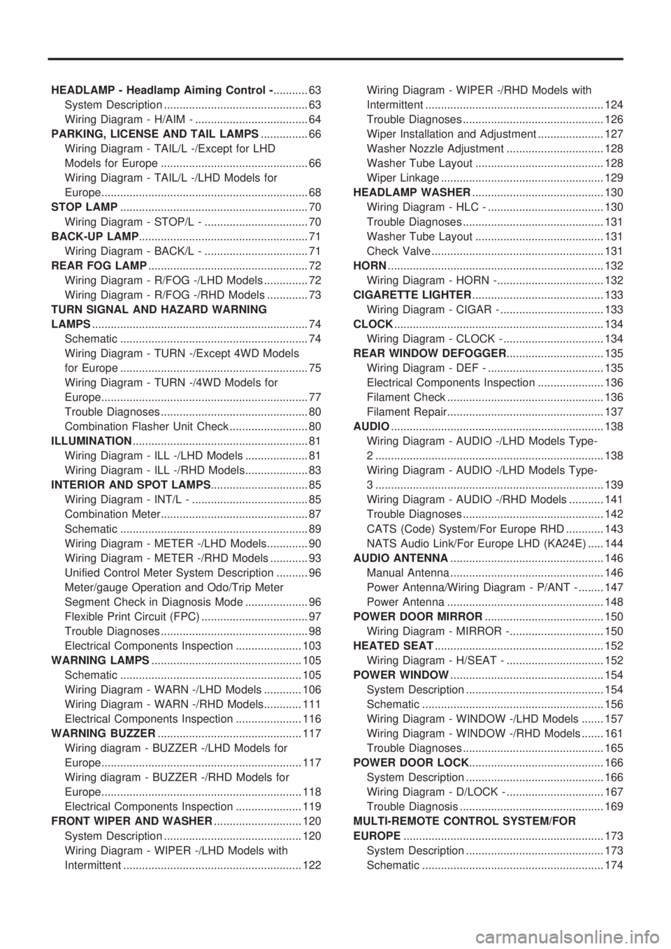
HEADLAMP - Headlamp Aiming Control -........... 63
System Description .............................................. 63
Wiring Diagram - H/AIM - .................................... 64
PARKING, LICENSE AND TAIL LAMPS............... 66
Wiring Diagram - TAIL/L -/Except for LHD
Models for Europe ............................................... 66
Wiring Diagram - TAIL/L -/LHD Models for
Europe.................................................................. 68
STOP LAMP............................................................ 70
Wiring Diagram - STOP/L - ................................. 70
BACK-UP LAMP...................................................... 71
Wiring Diagram - BACK/L - ................................. 71
REAR FOG LAMP................................................... 72
Wiring Diagram - R/FOG -/LHD Models .............. 72
Wiring Diagram - R/FOG -/RHD Models ............. 73
TURN SIGNAL AND HAZARD WARNING
LAMPS..................................................................... 74
Schematic ............................................................ 74
Wiring Diagram - TURN -/Except 4WD Models
for Europe ............................................................ 75
Wiring Diagram - TURN -/4WD Models for
Europe.................................................................. 77
Trouble Diagnoses ............................................... 80
Combination Flasher Unit Check ......................... 80
ILLUMINATION........................................................ 81
Wiring Diagram - ILL -/LHD Models .................... 81
Wiring Diagram - ILL -/RHD Models.................... 83
INTERIOR AND SPOT LAMPS............................... 85
Wiring Diagram - INT/L - ..................................... 85
Combination Meter............................................... 87
Schematic ............................................................ 89
Wiring Diagram - METER -/LHD Models............. 90
Wiring Diagram - METER -/RHD Models ............ 93
Unified Control Meter System Description .......... 96
Meter/gauge Operation and Odo/Trip Meter
Segment Check in Diagnosis Mode .................... 96
Flexible Print Circuit (FPC) .................................. 97
Trouble Diagnoses ............................................... 98
Electrical Components Inspection ..................... 103
WARNING LAMPS................................................ 105
Schematic .......................................................... 105
Wiring Diagram - WARN -/LHD Models ............ 106
Wiring Diagram - WARN -/RHD Models............ 111
Electrical Components Inspection ..................... 116
WARNING BUZZER.............................................. 117
Wiring diagram - BUZZER -/LHD Models for
Europe................................................................ 117
Wiring diagram - BUZZER -/RHD Models for
Europe................................................................ 118
Electrical Components Inspection ..................... 119
FRONT WIPER AND WASHER............................ 120
System Description ............................................ 120
Wiring Diagram - WIPER -/LHD Models with
Intermittent ......................................................... 122Wiring Diagram - WIPER -/RHD Models with
Intermittent ......................................................... 124
Trouble Diagnoses ............................................. 126
Wiper Installation and Adjustment ..................... 127
Washer Nozzle Adjustment ............................... 128
Washer Tube Layout ......................................... 128
Wiper Linkage .................................................... 129
HEADLAMP WASHER.......................................... 130
Wiring Diagram - HLC - ..................................... 130
Trouble Diagnoses ............................................. 131
Washer Tube Layout ......................................... 131
Check Valve ....................................................... 131
HORN..................................................................... 132
Wiring Diagram - HORN -.................................. 132
CIGARETTE LIGHTER.......................................... 133
Wiring Diagram - CIGAR - ................................. 133
CLOCK................................................................... 134
Wiring Diagram - CLOCK - ................................ 134
REAR WINDOW DEFOGGER............................... 135
Wiring Diagram - DEF - ..................................... 135
Electrical Components Inspection ..................... 136
Filament Check .................................................. 136
Filament Repair.................................................. 137
AUDIO.................................................................... 138
Wiring Diagram - AUDIO -/LHD Models Type-
2 ......................................................................... 138
Wiring Diagram - AUDIO -/LHD Models Type-
3 ......................................................................... 139
Wiring Diagram - AUDIO -/RHD Models ........... 141
Trouble Diagnoses ............................................. 142
CATS (Code) System/For Europe RHD ............ 143
NATS Audio Link/For Europe LHD (KA24E) ..... 144
AUDIO ANTENNA................................................. 146
Manual Antenna ................................................. 146
Power Antenna/Wiring Diagram - P/ANT - ........ 147
Power Antenna .................................................. 148
POWER DOOR MIRROR...................................... 150
Wiring Diagram - MIRROR -.............................. 150
HEATED SEAT...................................................... 152
Wiring Diagram - H/SEAT - ............................... 152
POWER WINDOW................................................. 154
System Description ............................................ 154
Schematic .......................................................... 156
Wiring Diagram - WINDOW -/LHD Models ....... 157
Wiring Diagram - WINDOW -/RHD Models ....... 161
Trouble Diagnoses ............................................. 165
POWER DOOR LOCK........................................... 166
System Description ............................................ 166
Wiring Diagram - D/LOCK - ............................... 167
Trouble Diagnosis .............................................. 169
MULTI-REMOTE CONTROL SYSTEM/FOR
EUROPE................................................................ 173
System Description ............................................ 173
Schematic .......................................................... 174
Page 404 of 1659
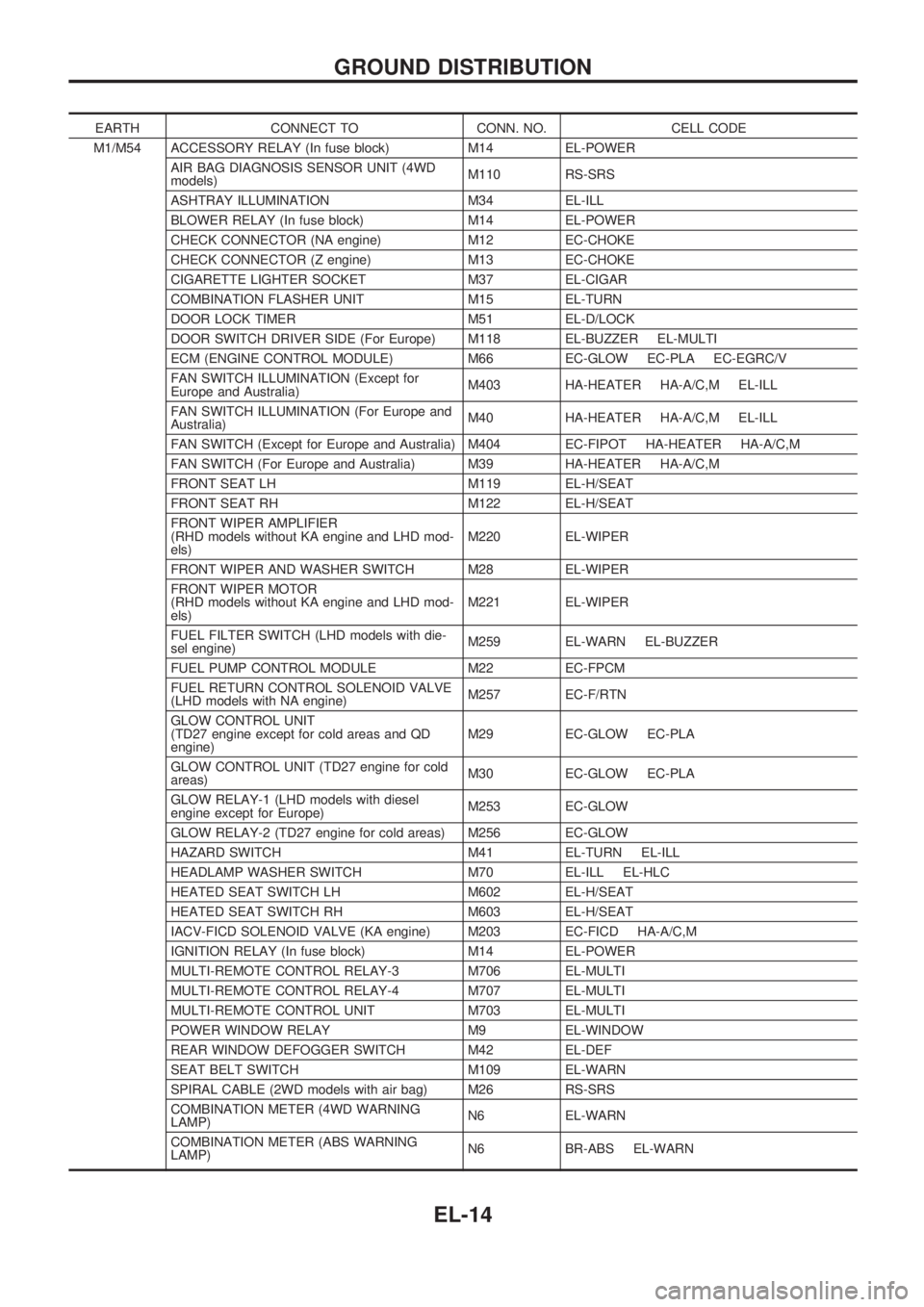
EARTH CONNECT TO CONN. NO. CELL CODE
M1/M54 ACCESSORY RELAY (In fuse block) M14 EL-POWER
AIR BAG DIAGNOSIS SENSOR UNIT (4WD
models)M110 RS-SRS
ASHTRAY ILLUMINATION M34 EL-ILL
BLOWER RELAY (In fuse block) M14 EL-POWER
CHECK CONNECTOR (NA engine) M12 EC-CHOKE
CHECK CONNECTOR (Z engine) M13 EC-CHOKE
CIGARETTE LIGHTER SOCKET M37 EL-CIGAR
COMBINATION FLASHER UNIT M15 EL-TURN
DOOR LOCK TIMER M51 EL-D/LOCK
DOOR SWITCH DRIVER SIDE (For Europe) M118 EL-BUZZER EL-MULTI
ECM (ENGINE CONTROL MODULE) M66 EC-GLOW EC-PLA EC-EGRC/V
FAN SWITCH ILLUMINATION (Except for
Europe and Australia)M403 HA-HEATER HA-A/C,M EL-ILL
FAN SWITCH ILLUMINATION (For Europe and
Australia)M40 HA-HEATER HA-A/C,M EL-ILL
FAN SWITCH (Except for Europe and Australia) M404 EC-FIPOT HA-HEATER HA-A/C,M
FAN SWITCH (For Europe and Australia) M39 HA-HEATER HA-A/C,M
FRONT SEAT LH M119 EL-H/SEAT
FRONT SEAT RH M122 EL-H/SEAT
FRONT WIPER AMPLIFIER
(RHD models without KA engine and LHD mod-
els)M220 EL-WIPER
FRONT WIPER AND WASHER SWITCH M28 EL-WIPER
FRONT WIPER MOTOR
(RHD models without KA engine and LHD mod-
els)M221 EL-WIPER
FUEL FILTER SWITCH (LHD models with die-
sel engine)M259 EL-WARN EL-BUZZER
FUEL PUMP CONTROL MODULE M22 EC-FPCM
FUEL RETURN CONTROL SOLENOID VALVE
(LHD models with NA engine)M257 EC-F/RTN
GLOW CONTROL UNIT
(TD27 engine except for cold areas and QD
engine)M29 EC-GLOW EC-PLA
GLOW CONTROL UNIT (TD27 engine for cold
areas)M30 EC-GLOW EC-PLA
GLOW RELAY-1 (LHD models with diesel
engine except for Europe)M253 EC-GLOW
GLOW RELAY-2 (TD27 engine for cold areas) M256 EC-GLOW
HAZARD SWITCH M41 EL-TURN EL-ILL
HEADLAMP WASHER SWITCH M70 EL-ILL EL-HLC
HEATED SEAT SWITCH LH M602 EL-H/SEAT
HEATED SEAT SWITCH RH M603 EL-H/SEAT
IACV-FICD SOLENOID VALVE (KA engine) M203 EC-FICD HA-A/C,M
IGNITION RELAY (In fuse block) M14 EL-POWER
MULTI-REMOTE CONTROL RELAY-3 M706 EL-MULTI
MULTI-REMOTE CONTROL RELAY-4 M707 EL-MULTI
MULTI-REMOTE CONTROL UNIT M703 EL-MULTI
POWER WINDOW RELAY M9 EL-WINDOW
REAR WINDOW DEFOGGER SWITCH M42 EL-DEF
SEAT BELT SWITCH M109 EL-WARN
SPIRAL CABLE (2WD models with air bag) M26 RS-SRS
COMBINATION METER (4WD WARNING
LAMP)N6 EL-WARN
COMBINATION METER (ABS WARNING
LAMP)N6 BR-ABS EL-WARN
GROUND DISTRIBUTION
EL-14
Page 405 of 1659
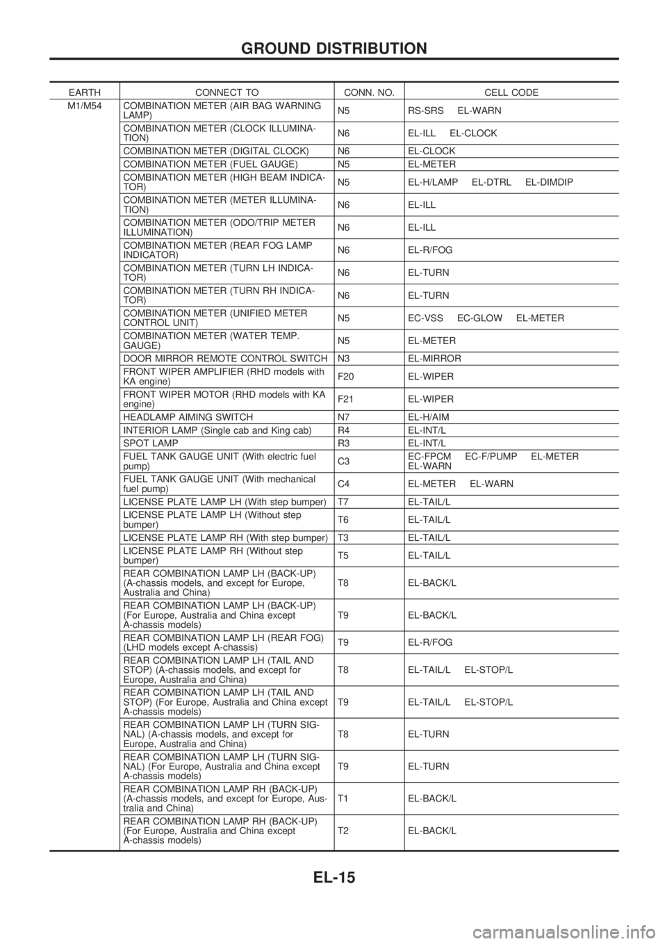
EARTH CONNECT TO CONN. NO. CELL CODE
M1/M54 COMBINATION METER (AIR BAG WARNING
LAMP)N5 RS-SRS EL-WARN
COMBINATION METER (CLOCK ILLUMINA-
TION)N6 EL-ILL EL-CLOCK
COMBINATION METER (DIGITAL CLOCK) N6 EL-CLOCK
COMBINATION METER (FUEL GAUGE) N5 EL-METER
COMBINATION METER (HIGH BEAM INDICA-
TOR)N5 EL-H/LAMP EL-DTRL EL-DIMDIP
COMBINATION METER (METER ILLUMINA-
TION)N6 EL-ILL
COMBINATION METER (ODO/TRIP METER
ILLUMINATION)N6 EL-ILL
COMBINATION METER (REAR FOG LAMP
INDICATOR)N6 EL-R/FOG
COMBINATION METER (TURN LH INDICA-
TOR)N6 EL-TURN
COMBINATION METER (TURN RH INDICA-
TOR)N6 EL-TURN
COMBINATION METER (UNIFIED METER
CONTROL UNIT)N5 EC-VSS EC-GLOW EL-METER
COMBINATION METER (WATER TEMP.
GAUGE)N5 EL-METER
DOOR MIRROR REMOTE CONTROL SWITCH N3 EL-MIRROR
FRONT WIPER AMPLIFIER (RHD models with
KA engine)F20 EL-WIPER
FRONT WIPER MOTOR (RHD models with KA
engine)F21 EL-WIPER
HEADLAMP AIMING SWITCH N7 EL-H/AIM
INTERIOR LAMP (Single cab and King cab) R4 EL-INT/L
SPOT LAMP R3 EL-INT/L
FUEL TANK GAUGE UNIT (With electric fuel
pump)C3EC-FPCM EC-F/PUMP EL-METER
EL-WARN
FUEL TANK GAUGE UNIT (With mechanical
fuel pump)C4 EL-METER EL-WARN
LICENSE PLATE LAMP LH (With step bumper) T7 EL-TAIL/L
LICENSE PLATE LAMP LH (Without step
bumper)T6 EL-TAIL/L
LICENSE PLATE LAMP RH (With step bumper) T3 EL-TAIL/L
LICENSE PLATE LAMP RH (Without step
bumper)T5 EL-TAIL/L
REAR COMBINATION LAMP LH (BACK-UP)
(A-chassis models, and except for Europe,
Australia and China)T8 EL-BACK/L
REAR COMBINATION LAMP LH (BACK-UP)
(For Europe, Australia and China except
A-chassis models)T9 EL-BACK/L
REAR COMBINATION LAMP LH (REAR FOG)
(LHD models except A-chassis)T9 EL-R/FOG
REAR COMBINATION LAMP LH (TAIL AND
STOP) (A-chassis models, and except for
Europe, Australia and China)T8 EL-TAIL/L EL-STOP/L
REAR COMBINATION LAMP LH (TAIL AND
STOP) (For Europe, Australia and China except
A-chassis models)T9 EL-TAIL/L EL-STOP/L
REAR COMBINATION LAMP LH (TURN SIG-
NAL) (A-chassis models, and except for
Europe, Australia and China)T8 EL-TURN
REAR COMBINATION LAMP LH (TURN SIG-
NAL) (For Europe, Australia and China except
A-chassis models)T9 EL-TURN
REAR COMBINATION LAMP RH (BACK-UP)
(A-chassis models, and except for Europe, Aus-
tralia and China)T1 EL-BACK/L
REAR COMBINATION LAMP RH (BACK-UP)
(For Europe, Australia and China except
A-chassis models)T2 EL-BACK/L
GROUND DISTRIBUTION
EL-15
Page 406 of 1659
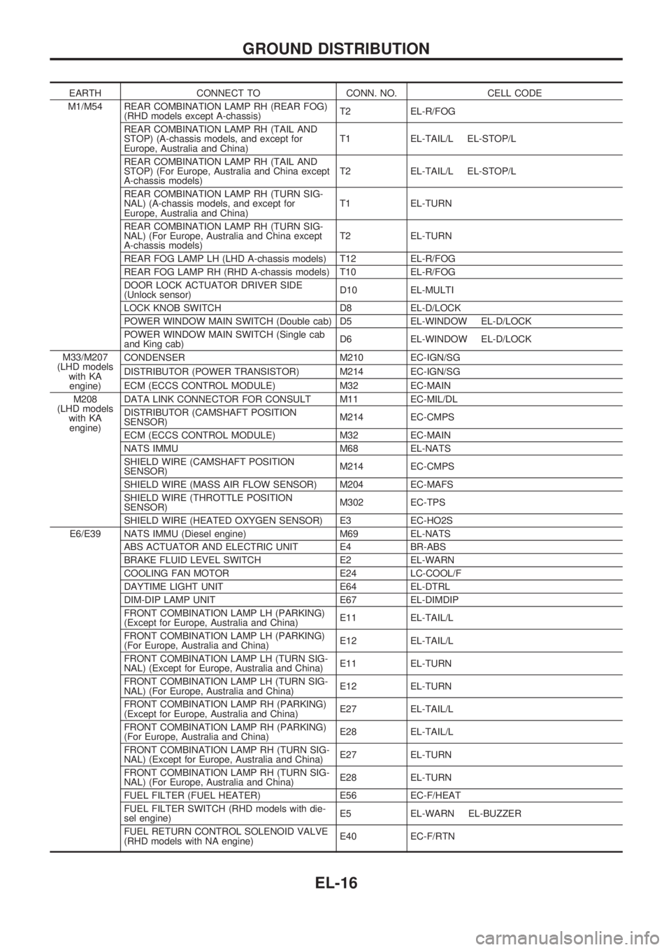
EARTH CONNECT TO CONN. NO. CELL CODE
M1/M54 REAR COMBINATION LAMP RH (REAR FOG)
(RHD models except A-chassis)T2 EL-R/FOG
REAR COMBINATION LAMP RH (TAIL AND
STOP) (A-chassis models, and except for
Europe, Australia and China)T1 EL-TAIL/L EL-STOP/L
REAR COMBINATION LAMP RH (TAIL AND
STOP) (For Europe, Australia and China except
A-chassis models)T2 EL-TAIL/L EL-STOP/L
REAR COMBINATION LAMP RH (TURN SIG-
NAL) (A-chassis models, and except for
Europe, Australia and China)T1 EL-TURN
REAR COMBINATION LAMP RH (TURN SIG-
NAL) (For Europe, Australia and China except
A-chassis models)T2 EL-TURN
REAR FOG LAMP LH (LHD A-chassis models) T12 EL-R/FOG
REAR FOG LAMP RH (RHD A-chassis models) T10 EL-R/FOG
DOOR LOCK ACTUATOR DRIVER SIDE
(Unlock sensor)D10 EL-MULTI
LOCK KNOB SWITCH D8 EL-D/LOCK
POWER WINDOW MAIN SWITCH (Double cab) D5 EL-WINDOW EL-D/LOCK
POWER WINDOW MAIN SWITCH (Single cab
and King cab)D6 EL-WINDOW EL-D/LOCK
M33/M207
(LHD models
with KA
engine)CONDENSER M210 EC-IGN/SG
DISTRIBUTOR (POWER TRANSISTOR) M214 EC-IGN/SG
ECM (ECCS CONTROL MODULE) M32 EC-MAIN
M208
(LHD models
with KA
engine)DATA LINK CONNECTOR FOR CONSULT M11 EC-MIL/DL
DISTRIBUTOR (CAMSHAFT POSITION
SENSOR)M214 EC-CMPS
ECM (ECCS CONTROL MODULE) M32 EC-MAIN
NATS IMMU M68 EL-NATS
SHIELD WIRE (CAMSHAFT POSITION
SENSOR)M214 EC-CMPS
SHIELD WIRE (MASS AIR FLOW SENSOR) M204 EC-MAFS
SHIELD WIRE (THROTTLE POSITION
SENSOR)M302 EC-TPS
SHIELD WIRE (HEATED OXYGEN SENSOR) E3 EC-HO2S
E6/E39 NATS IMMU (Diesel engine) M69 EL-NATS
ABS ACTUATOR AND ELECTRIC UNIT E4 BR-ABS
BRAKE FLUID LEVEL SWITCH E2 EL-WARN
COOLING FAN MOTOR E24 LC-COOL/F
DAYTIME LIGHT UNIT E64 EL-DTRL
DIM-DIP LAMP UNIT E67 EL-DIMDIP
FRONT COMBINATION LAMP LH (PARKING)
(Except for Europe, Australia and China)E11 EL-TAIL/L
FRONT COMBINATION LAMP LH (PARKING)
(For Europe, Australia and China)E12 EL-TAIL/L
FRONT COMBINATION LAMP LH (TURN SIG-
NAL) (Except for Europe, Australia and China)E11 EL-TURN
FRONT COMBINATION LAMP LH (TURN SIG-
NAL) (For Europe, Australia and China)E12 EL-TURN
FRONT COMBINATION LAMP RH (PARKING)
(Except for Europe, Australia and China)E27 EL-TAIL/L
FRONT COMBINATION LAMP RH (PARKING)
(For Europe, Australia and China)E28 EL-TAIL/L
FRONT COMBINATION LAMP RH (TURN SIG-
NAL) (Except for Europe, Australia and China)E27 EL-TURN
FRONT COMBINATION LAMP RH (TURN SIG-
NAL) (For Europe, Australia and China)E28 EL-TURN
FUEL FILTER (FUEL HEATER) E56 EC-F/HEAT
FUEL FILTER SWITCH (RHD models with die-
sel engine)E5 EL-WARN EL-BUZZER
FUEL RETURN CONTROL SOLENOID VALVE
(RHD models with NA engine)E40 EC-F/RTN
GROUND DISTRIBUTION
EL-16