key battery NISSAN PICK-UP 1998 Repair Manual
[x] Cancel search | Manufacturer: NISSAN, Model Year: 1998, Model line: PICK-UP, Model: NISSAN PICK-UP 1998Pages: 1659, PDF Size: 53.39 MB
Page 195 of 1659
DIAGNOSTIC TEST MODE IÐBULB CHECK
In this mode, the MALFUNCTION INDICATOR LAMP on the instrument panel should stay ON. If it remains
OFF, check the bulb. (See the WARNING LAMPS AND CHIME in the EL section. Or see EC-173, 174.)
DIAGNOSTIC TEST MODE IÐMALFUNCTION WARNING
MALFUNCTION
INDICATOR LAMPCondition
ON When the malfunction is detected (Refer to EC-1.) or the ECM's CPU is malfunctioning.
OFF No malfunction
lThese Diagnostic Trouble Code Numbers are clarified in Diagnostic Test Mode II (SELF-DIAGNOSTIC
RESULTS).
DIAGNOSTIC TEST MODE IIÐSELF-DIAGNOSTIC RESULTS
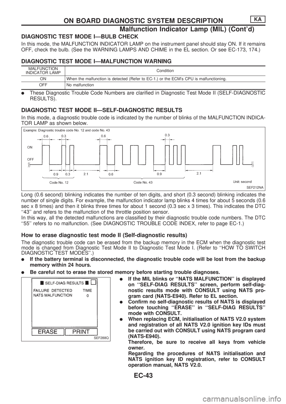
In this mode, a diagnostic trouble code is indicated by the number of blinks of the MALFUNCTION INDICA-
TOR LAMP as shown below.
Long (0.6 second) blinking indicates the number of ten digits, and short (0.3 second) blinking indicates the
number of single digits. For example, the malfunction indicator lamp blinks 4 times for about 5 seconds (0.6
sec x 8 times) and then it blinks three times for about 1 second (0.3 sec x 3 times). This indicates the DTC
``43'' and refers to the malfunction of the throttle position sensor.
In this way, all the detected malfunctions are classified by their diagnostic trouble code numbers. The DTC
``55'' refers to no malfunction. (See DIAGNOSTIC TROUBLE CODE INDEX, refer to page EC-1.)
How to erase diagnostic test mode II (Self-diagnostic results)
The diagnostic trouble code can be erased from the backup memory in the ECM when the diagnostic test
mode is changed from Diagnostic Test Mode II to Diagnostic Test Mode I. (Refer to ``HOW TO SWITCH
DIAGNOSTIC TEST MODES''.)
lIf the battery terminal is disconnected, the diagnostic trouble code will be lost from the backup
memory within 24 hours.
lBe careful not to erase the stored memory before starting trouble diagnoses.
lIf the MIL blinks or ``NATS MALFUNCTION'' is displayed
on ``SELF-DIAG RESULTS'' screen, perform self-diag-
nostic results mode with CONSULT using NATS pro-
gram card (NATS-E940). Refer to EL section.
lConfirm no self-diagnostic results of NATS is displayed
before touching ``ERASE'' in ``SELF-DIAG RESULTS''
mode with CONSULT.
lWhen replacing ECM, initialisation of NATS V2.0 system
and registration of all NATS V2.0 ignition key IDs must
be carried out with CONSULT using NATS program card
(NATS-E940).
Therefore, be sure to receive all keys from vehicle
owner.
Regarding the procedures of NATS initialisation and
NATS ignition key ID registration, refer to CONSULT
operation manual, NATS V2.0.
SEF212NA
SEF288Q
ON BOARD DIAGNOSTIC SYSTEM DESCRIPTIONKA
Malfunction Indicator Lamp (MIL) (Cont'd)
EC-43
Page 569 of 1659
Trouble Diagnoses
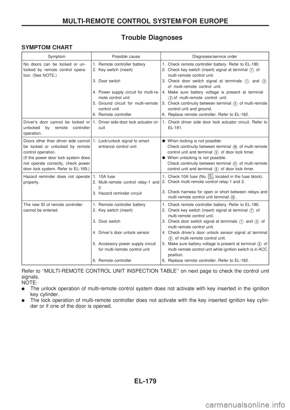
SYMPTOM CHART
Symptom Possible cause Diagnoses/service order
No doors can be locked or un-
locked by remote control opera-
tion. (See NOTE.)1. Remote controller battery
2. Key switch (insert)
3. Door switch
4. Power supply circuit for multi-re-
mote control unit
5. Ground circuit for multi-remote
control unit
6. Remote controller1. Check remote controller battery. Refer to EL-180.
2. Check key switch (insert) signal at terminal
V7of
multi-remote control unit.
3. Check door switch signal at terminals
V1andV2
of multi-remote control unit.
4. Make sure battery voltage is present at terminal
V3of multi-remote control unit.
5. Check continuity between terminal
V5of multi-remote
control unit and ground.
6. Replace remote controller. Refer to EL-182.
Driver's door cannot be locked or
unlocked by remote controller
operation.1. Driver side door lock actuator cir-
cuit1. Check driver side door lock actuator circuit. Refer to
EL-181.
Doors other than driver side cannot
be locked or unlocked by remote
control operation.
(If the power door lock system does
not operate correctly, check power
door lock system. Refer to EL-169.)1. Lock/unlock signal to smart
entrance control unit
lWhen locking is not possible:
Check continuity between terminal
V10of multi-remote
control unit and terminal
V5of door lock timer.
lWhen unlocking is not possible:
Check continuity between terminal
V11of multi-remote
control unit and terminal
V8of door lock timer.
Hazard reminder does not operate
properly.1. 10A fuse
2. Multi-remote control relay-1 and
2
3. Hazard reminder circuit1. Check 10A fuse (No.
5 , located in the fuse block).
2. Check multi-remote control relay-1 and 2.
3. Check harness for open or short between relays and
multi-remote control unit terminal
V12.
The new ID of remote controller
cannot be entered.1. Remote controller battery
2. Key switch (insert)
3. Door switch
4. Driver's door unlock sensor
5. Accessory power supply circuit
for multi-remote control unit
6. Remote controller1. Check remote controller battery. Refer to EL-180.
2. Check key switch (insert) signal at terminal
V7of
multi-remote control unit.
3. Check door switch signal at terminals
V1andV2of
multi-remote control unit.
4. Check driver's door unlock sensor signal at terminal
V6of multi-remote control unit.
5. Make sure battery voltage is present at terminal
V8of
multi-remote control unit while ignition switch is in ACC
position.
6. Replace remote controller. Refer to EL-182.
Refer to ``MULTI-REMOTE CONTROL UNIT INSPECTION TABLE'' on next page to check the control unit
signals.
NOTE:
lThe unlock operation of multi-remote control system does not activate with key inserted in the ignition
key cylinder.
lThe lock operation of multi-remote controller does not activate with the key inserted ignition key cylin-
der or if one of the door is opened.
MULTI-REMOTE CONTROL SYSTEM/FOR EUROPE
EL-179
Page 570 of 1659
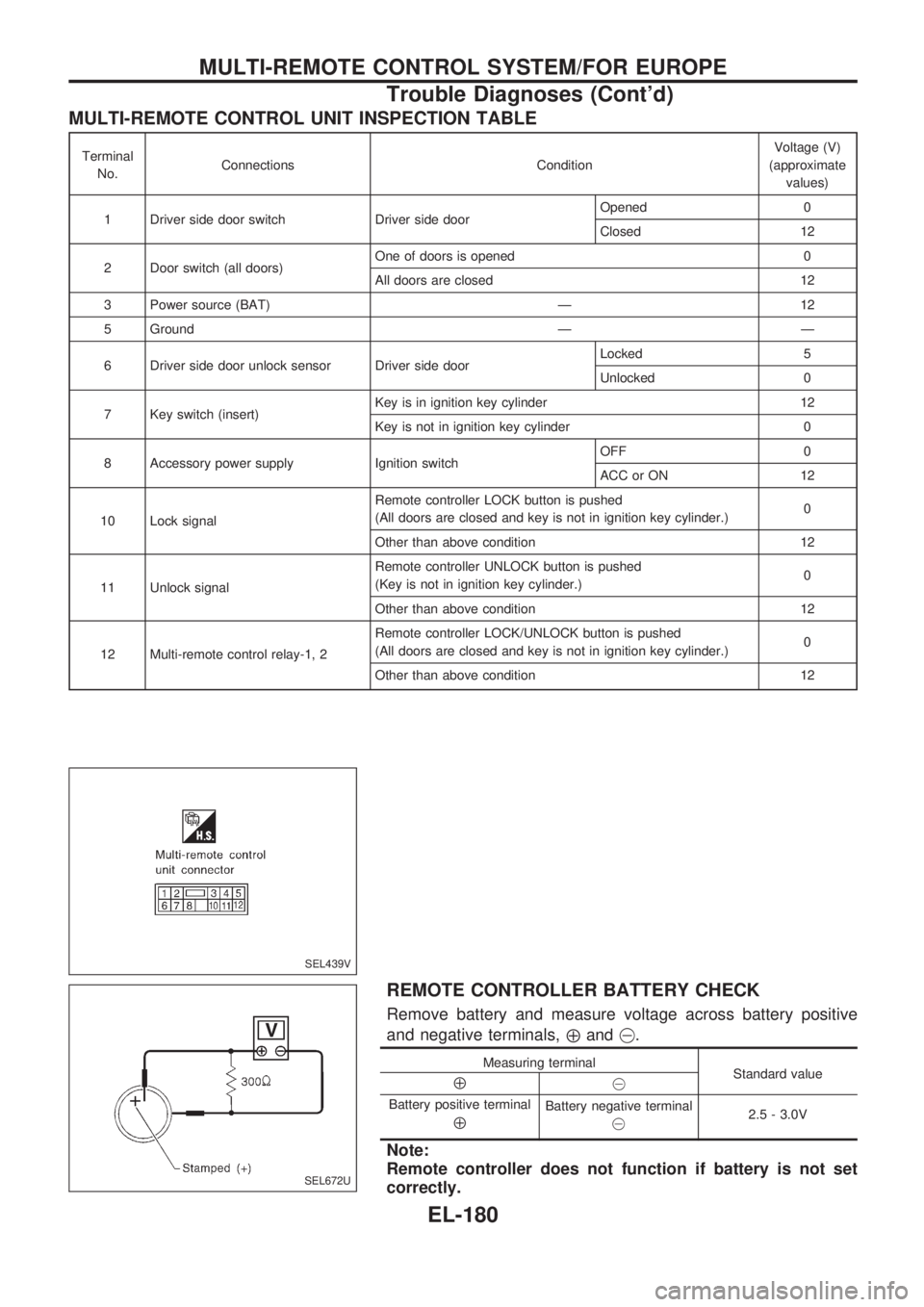
MULTI-REMOTE CONTROL UNIT INSPECTION TABLE
Terminal
No.Connections ConditionVoltage (V)
(approximate
values)
1 Driver side door switch Driver side doorOpened 0
Closed 12
2 Door switch (all doors)One of doors is opened 0
All doors are closed 12
3 Power source (BAT) Ð 12
5 Ground Ð Ð
6 Driver side door unlock sensor Driver side doorLocked 5
Unlocked 0
7 Key switch (insert)Key is in ignition key cylinder 12
Key is not in ignition key cylinder 0
8 Accessory power supply Ignition switchOFF 0
ACC or ON 12
10 Lock signalRemote controller LOCK button is pushed
(All doors are closed and key is not in ignition key cylinder.)0
Other than above condition 12
11 Unlock signalRemote controller UNLOCK button is pushed
(Key is not in ignition key cylinder.)0
Other than above condition 12
12 Multi-remote control relay-1, 2Remote controller LOCK/UNLOCK button is pushed
(All doors are closed and key is not in ignition key cylinder.)0
Other than above condition 12
REMOTE CONTROLLER BATTERY CHECK
Remove battery and measure voltage across battery positive
and negative terminals,
Åand@.
Measuring terminal
Standard value
Å@
Battery positive terminal
Å
Battery negative terminal
@2.5 - 3.0V
Note:
Remote controller does not function if battery is not set
correctly.
SEL439V
SEL672U
MULTI-REMOTE CONTROL SYSTEM/FOR EUROPE
Trouble Diagnoses (Cont'd)
EL-180
Page 579 of 1659
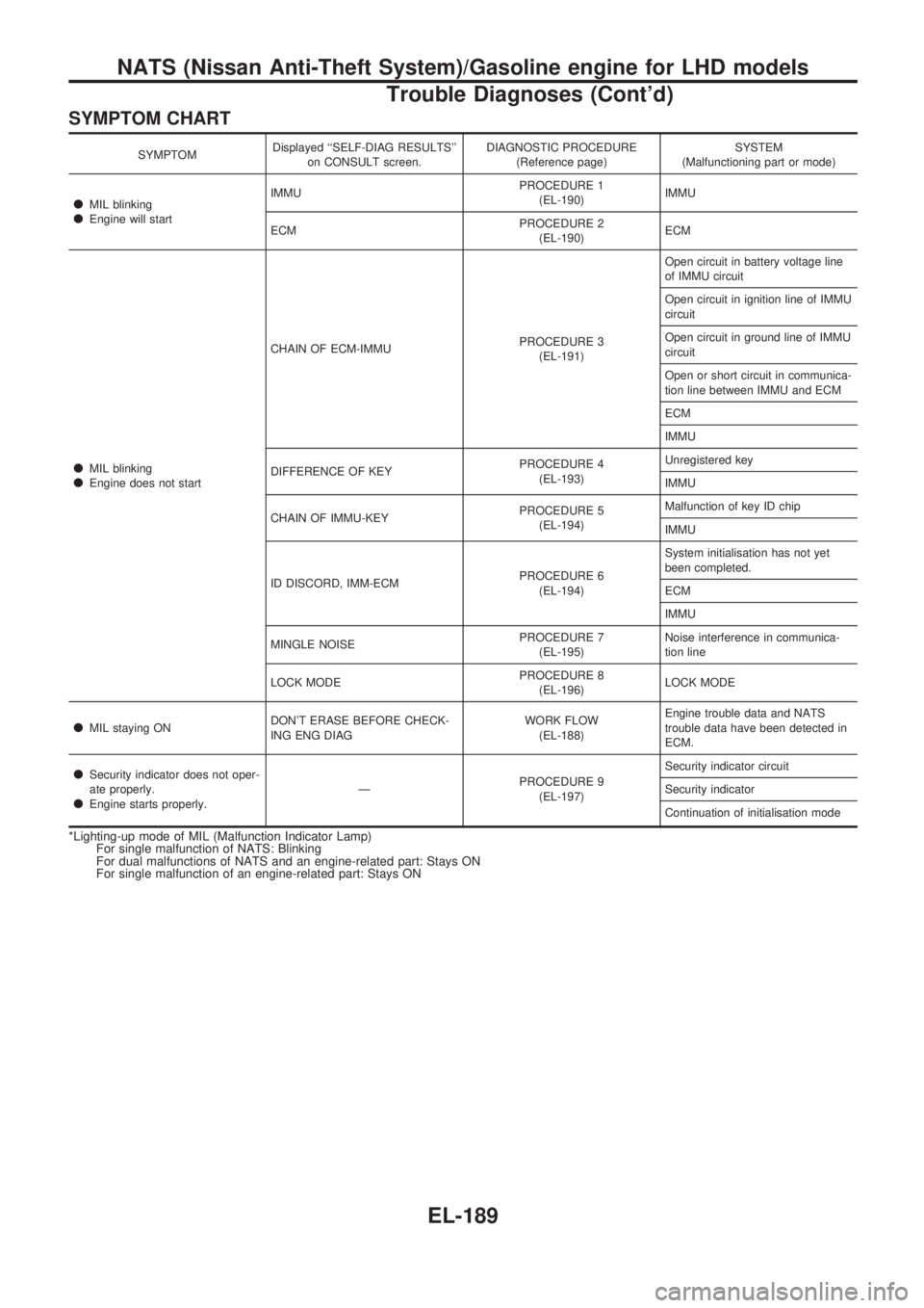
SYMPTOM CHART
SYMPTOMDisplayed ``SELF-DIAG RESULTS''
on CONSULT screen.DIAGNOSTIC PROCEDURE
(Reference page)SYSTEM
(Malfunctioning part or mode)
lMIL blinkinglEngine will startIMMUPROCEDURE 1
(EL-190)IMMU
ECMPROCEDURE 2
(EL-190)ECM
lMIL blinkinglEngine does not startCHAIN OF ECM-IMMUPROCEDURE 3
(EL-191)Open circuit in battery voltage line
of IMMU circuit
Open circuit in ignition line of IMMU
circuit
Open circuit in ground line of IMMU
circuit
Open or short circuit in communica-
tion line between IMMU and ECM
ECM
IMMU
DIFFERENCE OF KEYPROCEDURE 4
(EL-193)Unregistered key
IMMU
CHAIN OF IMMU-KEYPROCEDURE 5
(EL-194)Malfunction of key ID chip
IMMU
ID DISCORD, IMM-ECMPROCEDURE 6
(EL-194)System initialisation has not yet
been completed.
ECM
IMMU
MINGLE NOISEPROCEDURE 7
(EL-195)Noise interference in communica-
tion line
LOCK MODEPROCEDURE 8
(EL-196)LOCK MODE
lMIL staying ONDON'T ERASE BEFORE CHECK-
ING ENG DIAGWORK FLOW
(EL-188)Engine trouble data and NATS
trouble data have been detected in
ECM.
lSecurity indicator does not oper-
ate properly.
lEngine starts properly.ÐPROCEDURE 9
(EL-197)Security indicator circuit
Security indicator
Continuation of initialisation mode
*Lighting-up mode of MIL (Malfunction Indicator Lamp)
For single malfunction of NATS: Blinking
For dual malfunctions of NATS and an engine-related part: Stays ON
For single malfunction of an engine-related part: Stays ON
NATS (Nissan Anti-Theft System)/Gasoline engine for LHD models
Trouble Diagnoses (Cont'd)
EL-189
Page 587 of 1659
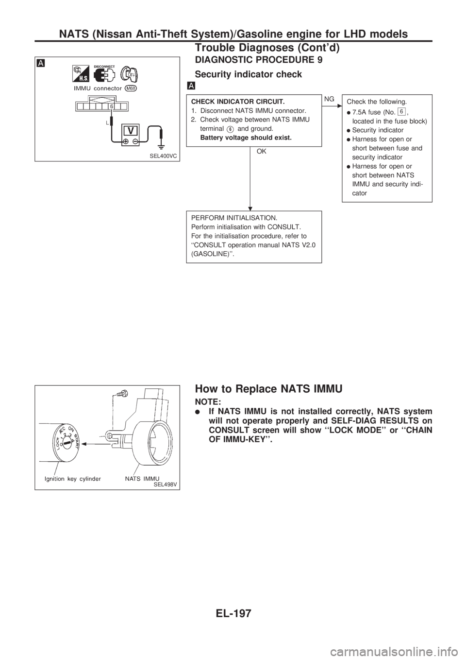
DIAGNOSTIC PROCEDURE 9
Security indicator check
CHECK INDICATOR CIRCUIT.
1. Disconnect NATS IMMU connector.
2. Check voltage between NATS IMMU
terminal
V6and ground.
Battery voltage should exist.
OK
cNG
Check the following.
l7.5A fuse (No.6,
located in the fuse block)
lSecurity indicator
lHarness for open or
short between fuse and
security indicator
lHarness for open or
short between NATS
IMMU and security indi-
cator
PERFORM INITIALISATION.
Perform initialisation with CONSULT.
For the initialisation procedure, refer to
``CONSULT operation manual NATS V2.0
(GASOLINE)''.
How to Replace NATS IMMU
NOTE:
lIf NATS IMMU is not installed correctly, NATS system
will not operate properly and SELF-DIAG RESULTS on
CONSULT screen will show ``LOCK MODE'' or ``CHAIN
OF IMMU-KEY''.
SEL400VC
SEL498V
.
NATS (Nissan Anti-Theft System)/Gasoline engine for LHD models
Trouble Diagnoses (Cont'd)
EL-197
Page 807 of 1659
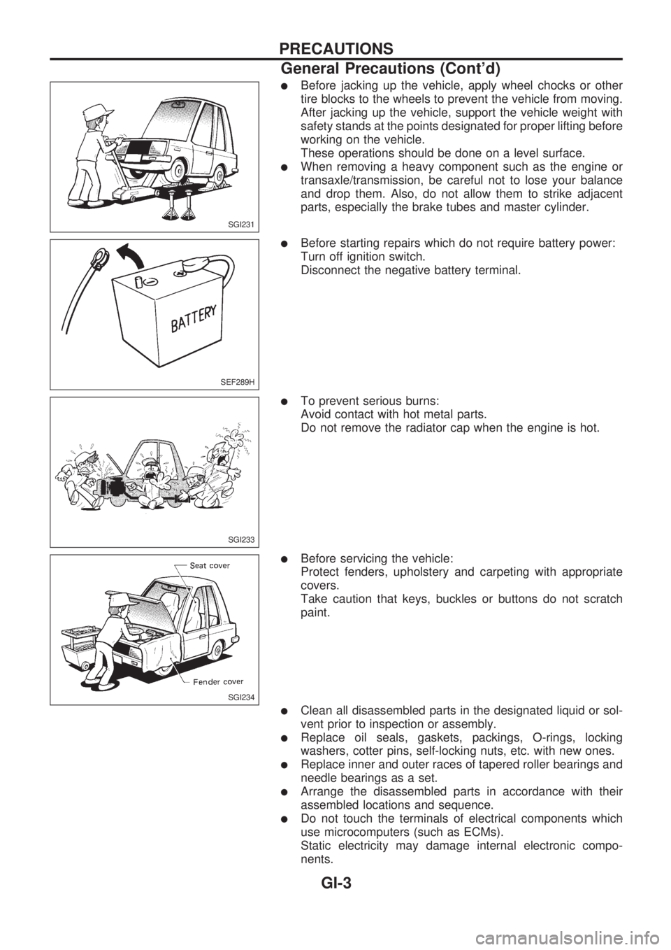
lBefore jacking up the vehicle, apply wheel chocks or other
tire blocks to the wheels to prevent the vehicle from moving.
After jacking up the vehicle, support the vehicle weight with
safety stands at the points designated for proper lifting before
working on the vehicle.
These operations should be done on a level surface.
lWhen removing a heavy component such as the engine or
transaxle/transmission, be careful not to lose your balance
and drop them. Also, do not allow them to strike adjacent
parts, especially the brake tubes and master cylinder.
lBefore starting repairs which do not require battery power:
Turn off ignition switch.
Disconnect the negative battery terminal.
lTo prevent serious burns:
Avoid contact with hot metal parts.
Do not remove the radiator cap when the engine is hot.
lBefore servicing the vehicle:
Protect fenders, upholstery and carpeting with appropriate
covers.
Take caution that keys, buckles or buttons do not scratch
paint.
lClean all disassembled parts in the designated liquid or sol-
vent prior to inspection or assembly.
lReplace oil seals, gaskets, packings, O-rings, locking
washers, cotter pins, self-locking nuts, etc. with new ones.
lReplace inner and outer races of tapered roller bearings and
needle bearings as a set.
lArrange the disassembled parts in accordance with their
assembled locations and sequence.
lDo not touch the terminals of electrical components which
use microcomputers (such as ECMs).
Static electricity may damage internal electronic compo-
nents.
SGI231
SEF289H
SGI233
SGI234
PRECAUTIONS
General Precautions (Cont'd)
GI-3
Page 831 of 1659
Voltage check method
1. Remove the blown fuse and disconnect all loads (i.e. SW1 open, relay disconnected and solenoid dis-
connected) powered through the fuse.
2. Turn the ignition key to the ON or START position. Verify battery voltage at the B
+side of the fuse ter-
minal (one lead on the B
+terminal side of the fuse block and one lead on a known good ground).
3. With SW1 open and the DMM leads across both fuse terminals, check for voltage.
voltage; short is between fuse block and SW1 (point A).
no voltage; short is further down the circuit than SW1.
4. With SW1 closed, relay and solenoid disconnected and the DMM leads across both fuse terminals, check
for voltage.
voltage; short is between SW1 and the relay (point B).
no voltage; short is further down the circuit than the relay.
5. With SW1 closed, relay contacts jumped with fused jumper wire check for voltage.
voltage; short is down the circuit of the relay or between the relay and the disconnected solenoid
(point C).
no voltage; retrace steps and check power to fuse block.
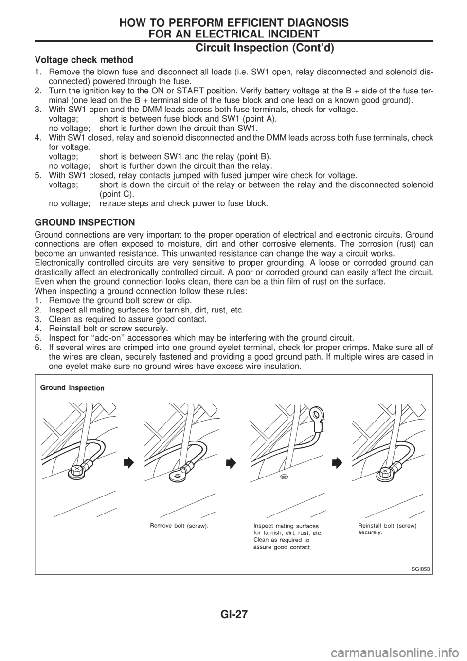
GROUND INSPECTION
Ground connections are very important to the proper operation of electrical and electronic circuits. Ground
connections are often exposed to moisture, dirt and other corrosive elements. The corrosion (rust) can
become an unwanted resistance. This unwanted resistance can change the way a circuit works.
Electronically controlled circuits are very sensitive to proper grounding. A loose or corroded ground can
drastically affect an electronically controlled circuit. A poor or corroded ground can easily affect the circuit.
Even when the ground connection looks clean, there can be a thin film of rust on the surface.
When inspecting a ground connection follow these rules:
1. Remove the ground bolt screw or clip.
2. Inspect all mating surfaces for tarnish, dirt, rust, etc.
3. Clean as required to assure good contact.
4. Reinstall bolt or screw securely.
5. Inspect for ``add-on'' accessories which may be interfering with the ground circuit.
6. If several wires are crimped into one ground eyelet terminal, check for proper crimps. Make sure all of
the wires are clean, securely fastened and providing a good ground path. If multiple wires are cased in
one eyelet make sure no ground wires have excess wire insulation.
SGI853
HOW TO PERFORM EFFICIENT DIAGNOSIS
FOR AN ELECTRICAL INCIDENT
Circuit Inspection (Cont'd)
GI-27
Page 837 of 1659
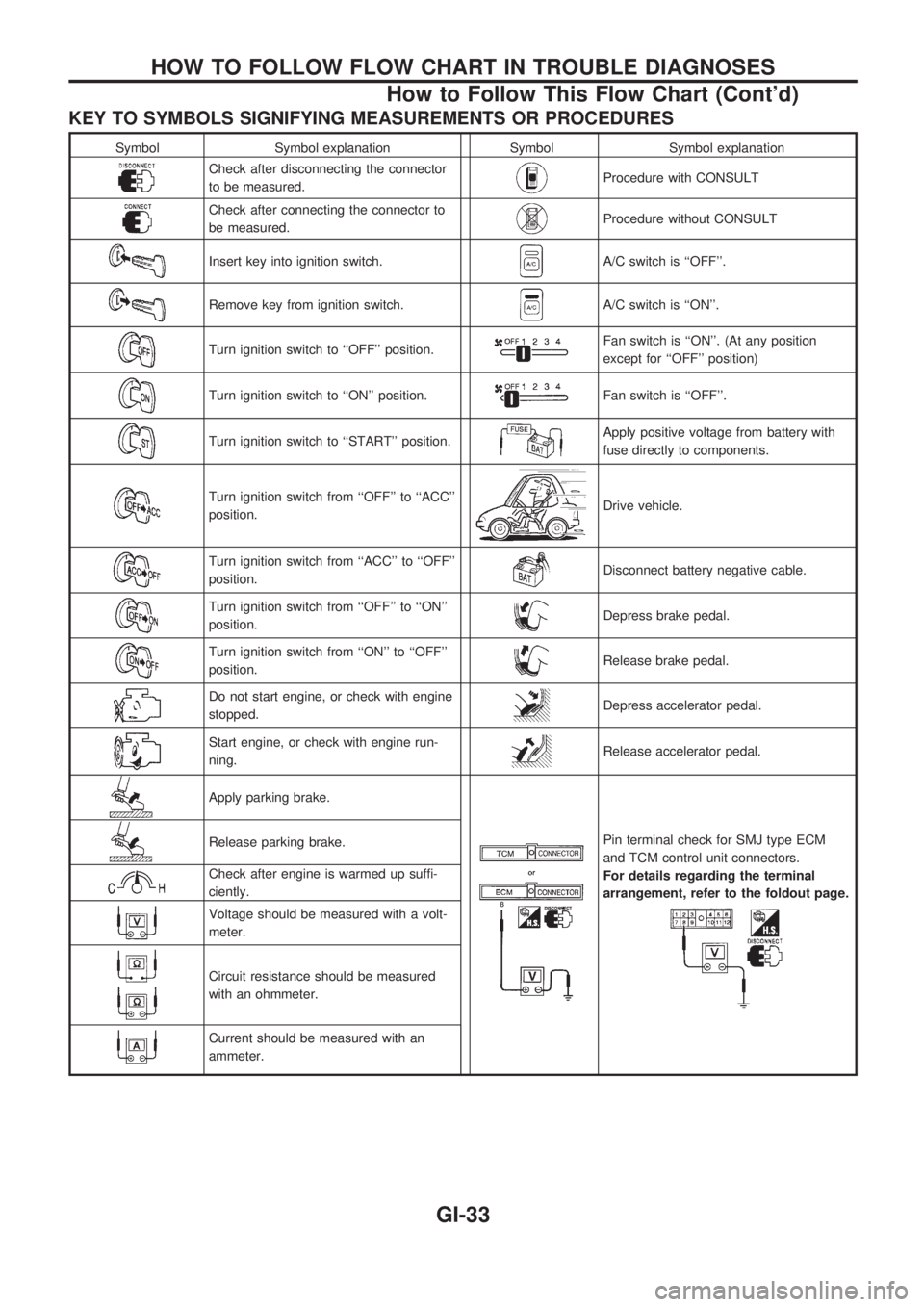
KEY TO SYMBOLS SIGNIFYING MEASUREMENTS OR PROCEDURES
Symbol Symbol explanation Symbol Symbol explanation
Check after disconnecting the connector
to be measured.Procedure with CONSULT
Check after connecting the connector to
be measured.Procedure without CONSULT
Insert key into ignition switch.A/C switch is ``OFF''.
Remove key from ignition switch.A/C switch is ``ON''.
Turn ignition switch to ``OFF'' position.Fan switch is ``ON''. (At any position
except for ``OFF'' position)
Turn ignition switch to ``ON'' position.Fan switch is ``OFF''.
Turn ignition switch to ``START'' position.Apply positive voltage from battery with
fuse directly to components.
Turn ignition switch from ``OFF'' to ``ACC''
position.Drive vehicle.
Turn ignition switch from ``ACC'' to ``OFF''
position.Disconnect battery negative cable.
Turn ignition switch from ``OFF'' to ``ON''
position.Depress brake pedal.
Turn ignition switch from ``ON'' to ``OFF''
position.Release brake pedal.
Do not start engine, or check with engine
stopped.Depress accelerator pedal.
Start engine, or check with engine run-
ning.Release accelerator pedal.
Apply parking brake.
Pin terminal check for SMJ type ECM
and TCM control unit connectors.
For details regarding the terminal
arrangement, refer to the foldout page.Release parking brake.
Check after engine is warmed up suffi-
ciently.
Voltage should be measured with a volt-
meter.
Circuit resistance should be measured
with an ohmmeter.
Current should be measured with an
ammeter.
HOW TO FOLLOW FLOW CHART IN TROUBLE DIAGNOSES
How to Follow This Flow Chart (Cont'd)
GI-33
Page 838 of 1659
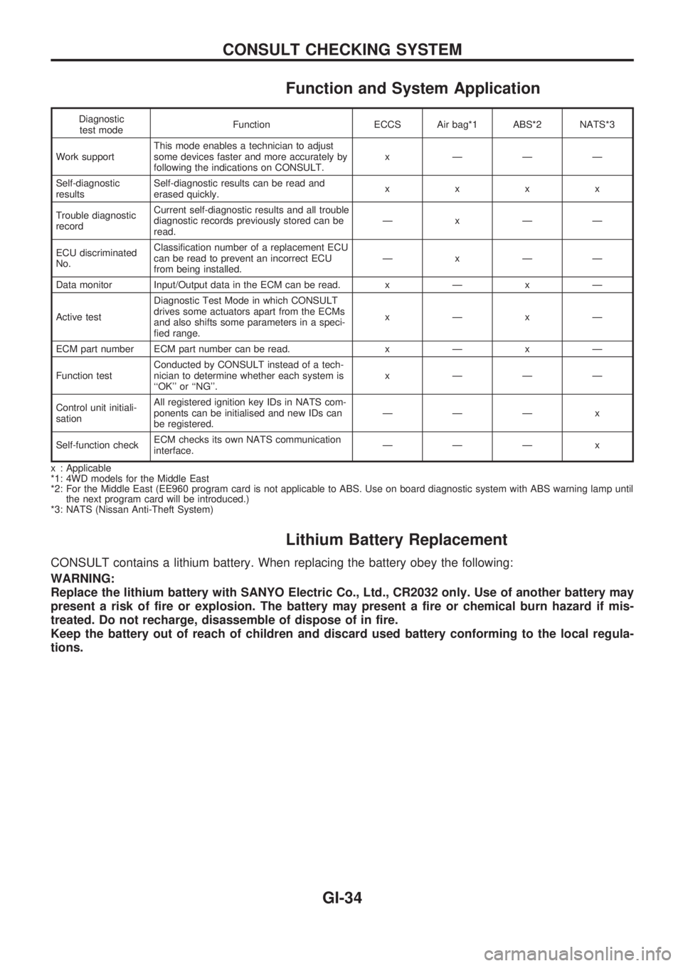
Function and System Application
Diagnostic
test modeFunction ECCS Air bag*1 ABS*2 NATS*3
Work supportThis mode enables a technician to adjust
some devices faster and more accurately by
following the indications on CONSULT.x ÐÐÐ
Self-diagnostic
resultsSelf-diagnostic results can be read and
erased quickly.xxxx
Trouble diagnostic
recordCurrent self-diagnostic results and all trouble
diagnostic records previously stored can be
read.ÐxÐÐ
ECU discriminated
No.Classification number of a replacement ECU
can be read to prevent an incorrect ECU
from being installed.ÐxÐÐ
Data monitor Input/Output data in the ECM can be read.xÐxÐ
Active testDiagnostic Test Mode in which CONSULT
drives some actuators apart from the ECMs
and also shifts some parameters in a speci-
fied range.xÐxÐ
ECM part number ECM part number can be read.xÐxÐ
Function testConducted by CONSULT instead of a tech-
nician to determine whether each system is
``OK'' or ``NG''.x ÐÐÐ
Control unit initiali-
sationAll registered ignition key IDs in NATS com-
ponents can be initialised and new IDs can
be registered.ÐÐÐ x
Self-function checkECM checks its own NATS communication
interface.ÐÐÐ x
x : Applicable
*1: 4WD models for the Middle East
*2: For the Middle East (EE960 program card is not applicable to ABS. Use on board diagnostic system with ABS warning lamp until
the next program card will be introduced.)
*3: NATS (Nissan Anti-Theft System)
Lithium Battery Replacement
CONSULT contains a lithium battery. When replacing the battery obey the following:
WARNING:
Replace the lithium battery with SANYO Electric Co., Ltd., CR2032 only. Use of another battery may
present a risk of fire or explosion. The battery may present a fire or chemical burn hazard if mis-
treated. Do not recharge, disassemble of dispose of in fire.
Keep the battery out of reach of children and discard used battery conforming to the local regula-
tions.
CONSULT CHECKING SYSTEM
GI-34
Page 976 of 1659
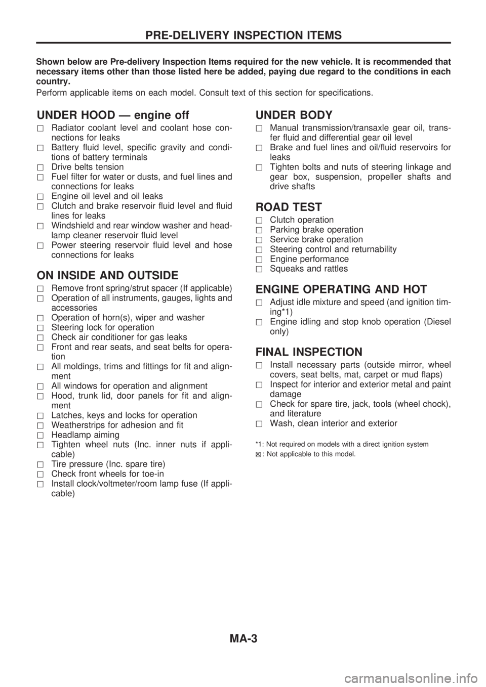
Shown below are Pre-delivery Inspection Items required for the new vehicle. It is recommended that
necessary items other than those listed here be added, paying due regard to the conditions in each
country.
Perform applicable items on each model. Consult text of this section for specifications.
UNDER HOOD Ð engine off
hRadiator coolant level and coolant hose con-
nections for leaks
hBattery fluid level, specific gravity and condi-
tions of battery terminals
hDrive belts tension
hFuel filter for water or dusts, and fuel lines and
connections for leaks
hEngine oil level and oil leaks
hClutch and brake reservoir fluid level and fluid
lines for leaks
hWindshield and rear window washer and head-
lamp cleaner reservoir fluid level
hPower steering reservoir fluid level and hose
connections for leaks
ON INSIDE AND OUTSIDE
hRemove front spring/strut spacer (If applicable)
hOperation of all instruments, gauges, lights and
accessories
hOperation of horn(s), wiper and washer
hSteering lock for operation
hCheck air conditioner for gas leaks
hFront and rear seats, and seat belts for opera-
tion
hAll moldings, trims and fittings for fit and align-
ment
hAll windows for operation and alignment
hHood, trunk lid, door panels for fit and align-
ment
hLatches, keys and locks for operation
hWeatherstrips for adhesion and fit
hHeadlamp aiming
hTighten wheel nuts (Inc. inner nuts if appli-
cable)
hTire pressure (Inc. spare tire)
hCheck front wheels for toe-in
hInstall clock/voltmeter/room lamp fuse (If appli-
cable)
UNDER BODY
hManual transmission/transaxle gear oil, trans-
fer fluid and differential gear oil level
hBrake and fuel lines and oil/fluid reservoirs for
leaks
hTighten bolts and nuts of steering linkage and
gear box, suspension, propeller shafts and
drive shafts
ROAD TEST
hClutch operation
hParking brake operation
hService brake operation
hSteering control and returnability
hEngine performance
hSqueaks and rattles
ENGINE OPERATING AND HOT
hAdjust idle mixture and speed (and ignition tim-
ing*1)
hEngine idling and stop knob operation (Diesel
only)
FINAL INSPECTION
hInstall necessary parts (outside mirror, wheel
covers, seat belts, mat, carpet or mud flaps)
hInspect for interior and exterior metal and paint
damage
hCheck for spare tire, jack, tools (wheel chock),
and literature
hWash, clean interior and exterior
*1: Not required on models with a direct ignition system
h
X: Not applicable to this model.
PRE-DELIVERY INSPECTION ITEMS
MA-3