roof NISSAN PICK-UP 1998 Repair Manual
[x] Cancel search | Manufacturer: NISSAN, Model Year: 1998, Model line: PICK-UP, Model: NISSAN PICK-UP 1998Pages: 1659, PDF Size: 53.39 MB
Page 96 of 1659

WATERPROOF Ð for 4WD model
lApply recommended sealant to contact surface of transmis-
sion case dust cover and withdrawal lever, then install dust
cover clip.
Recommended sealant:
Nissan genuine part KP115-00100, Three Bond TB
1212 or equivalent.
SCL760
SCL761
CLUTCH RELEASE MECHANISM
CL-11
Page 100 of 1659
BODY & TRIM
SECTIONBT
CONTENTS
PRECAUTIONS......................................................... 1
Service Notice ........................................................ 1
Supplemental Restraint System (SRS) ``AIR
BAG'' (4WD models).............................................. 1
Supplemental Restraint System (SRS) ``AIR
BAG'' (2WD models).............................................. 1
GENERAL SERVICING............................................. 2
Clip and Fastener .................................................. 2
BODY END................................................................ 5
Body Front End ...................................................... 5
Body Rear End ...................................................... 8
DOOR....................................................................... 10
Front Door ............................................................ 10
Rear Door ............................................................ 11
INSTRUMENT PANEL............................................. 12
INTERIOR TRIM...................................................... 15
Side and Floor Trim ............................................. 15
Door Trim ............................................................. 18
Roof Trim ............................................................. 21EXTERIOR............................................................... 24
SEAT........................................................................ 30
Front Seat ............................................................ 30
Heated Seat ......................................................... 32
Rear Seat ............................................................. 33
Jump Seat ............................................................ 34
SUNROOF................................................................ 35
WINDSHIELD AND WINDOWS.............................. 36
Windshield............................................................ 37
Side Window ........................................................ 38
MIRROR................................................................... 39
Door Mirror ........................................................... 39
CAB AND REAR BODY.......................................... 40
Removal ............................................................... 40
Body Mounting ..................................................... 41
BODY ALIGNMENT................................................. 43
Engine Compartment ........................................... 44
Underbody............................................................ 46
.For seat belt, refer to MA and RS section.
.For wiring diagrams of body electrical systems, refer to EL section.BT
Page 121 of 1659
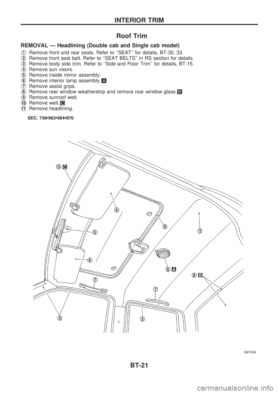
Roof Trim
REMOVAL Ð Headlining (Double cab and Single cab model)
V1Remove front and rear seats. Refer to ``SEAT'' for details, BT-30, 33.
V2Remove front seat belt. Refer to ``SEAT BELTS'' in RS section for details.
V3Remove body side trim. Refer to ``Side and Floor Trim'' for details, BT-15.
V4Remove sun visors.
V5Remove inside mirror assembly.
V6Remove interior lamp assembly.
V7Remove assist grips.
V8Remove rear window weatherstrip and remove rear window glass.
V9Remove sunroof welt.
V10Remove welt.
V11Remove headlining.
SBT439
INTERIOR TRIM
BT-21
Page 122 of 1659

SBT440
INTERIOR TRIM
Roof Trim (Cont'd)
BT-22
Page 123 of 1659
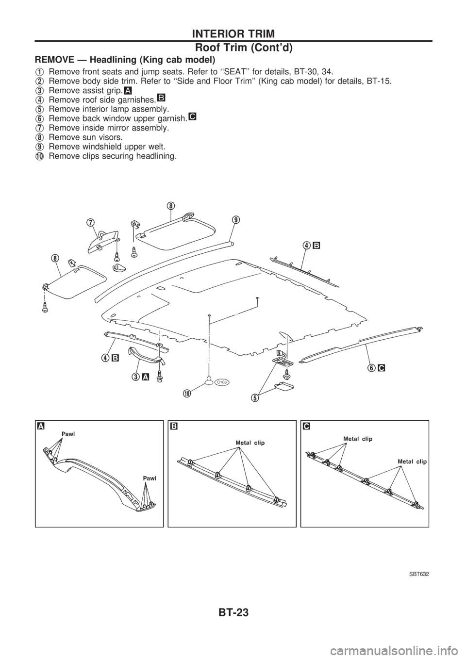
REMOVE Ð Headlining (King cab model)
V1Remove front seats and jump seats. Refer to ``SEAT'' for details, BT-30, 34.
V2Remove body side trim. Refer to ``Side and Floor Trim'' (King cab model) for details, BT-15.
V3Remove assist grip.
V4Remove roof side garnishes.
V5Remove interior lamp assembly.
V6Remove back window upper garnish.
V7Remove inside mirror assembly.
V8Remove sun visors.
V9Remove windshield upper welt.
V10Remove clips securing headlining.
SBT632
INTERIOR TRIM
Roof Trim (Cont'd)
BT-23
Page 125 of 1659

V1Hood front sealing rubber
V2Cowl top seal and cowl top grille
V3Windshield side molding
Mounted with screws.
V4Windshield upper molding
V5Sunroof weatherstrip and lid protector
SBT442
SBT443
SBT444-A
SBT445
EXTERIOR
BT-25
Page 135 of 1659

SBT456
SUNROOF
BT-35
Page 611 of 1659

How to Read Harness Layout
Example:
G2E1B/6: ASCD ACTUATOR
Connector color / Cavity
Connector number
Grid reference
The following Harness Layouts use a map style grid to help locate connectors on the drawings:
lMain Harness (Instrument Panel, Engine Compartment)
lEngine Room Harness
lEngine Control Harness
To use the grid reference
1) Find the desired connector number on the connector list.
2) Find the grid reference.
3) On the drawing, find the crossing of the grid reference letter column and number row.
4) Find the connector number in the crossing zone.
5) Follow the line (if used) to the connector.
CONNECTOR SYMBOL
Main symbols of connector (in Harness Layout) are indicated in the below.
Connector typeWater proof type Standard type
Male Female Male Female
lCavity: Less than 4
lRelay connector
lCavity: From 5 to 8
lCavity: More than 9
lGround terminal etc.
Ð
HARNESS LAYOUT
EL-221
Page 759 of 1659
WARNING:
When replacing fuel line parts, be sure to observe the following:
lPut a ``CAUTION: INFLAMMABLE'' sign in workshop.
lDo not smoke while servicing fuel system. Keep open flames and sparks away from work area.
lBe sure to disconnect battery ground cable before conducting operations.
lBe sure to furnish workshop with a CO2fire extinguisher.
lDrain fuel from fuel tank and put drained fuel in an explosion-proof container and put lid on
securely.
CAUTION:
lBefore disconnecting fuel hose of ECCS engine model, release fuel pressure from fuel line. Refer
to ``Changing Fuel Filter'' in MA section.
lDo not disconnect any fuel line unless absolutely necessary.
lPlug hose and pipe openings to prevent entry of dust or dirt.
lAlways replace O-ring and clamps with new ones.
lDo not kink or twist hose and tube when they are installed.
lDo not tighten hose clamps excessively to avoid damaging hoses.
lWhen installing fuel check valve, be careful of its designated direction. (Refer to ``EVAPORATIVE
EMISSION SYSTEM'' in EC section.)
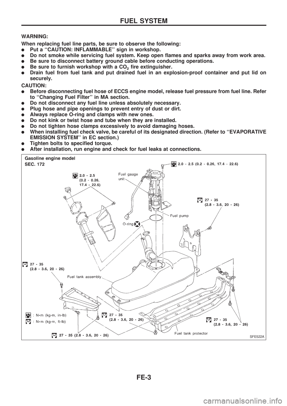
lTighten bolts to specified torque.
lAfter installation, run engine and check for fuel leaks at connections.
SFE522A
FUEL SYSTEM
FE-3
Page 804 of 1659
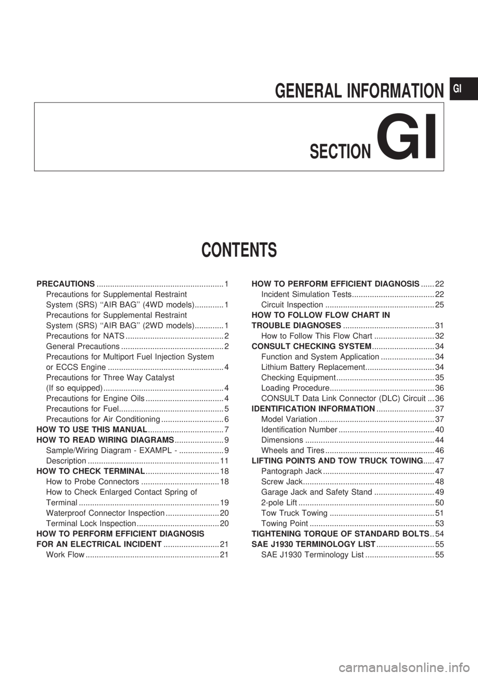
GENERAL INFORMATION
SECTION
GI
CONTENTS
PRECAUTIONS......................................................... 1
Precautions for Supplemental Restraint
System (SRS) ``AIR BAG'' (4WD models)............. 1
Precautions for Supplemental Restraint
System (SRS) ``AIR BAG'' (2WD models)............. 1
Precautions for NATS ............................................ 2
General Precautions .............................................. 2
Precautions for Multiport Fuel Injection System
or ECCS Engine .................................................... 4
Precautions for Three Way Catalyst
(If so equipped) ...................................................... 4
Precautions for Engine Oils ................................... 4
Precautions for Fuel............................................... 5
Precautions for Air Conditioning ............................ 6
HOW TO USE THIS MANUAL.................................. 7
HOW TO READ WIRING DIAGRAMS...................... 9
Sample/Wiring Diagram - EXAMPL - .................... 9
Description ........................................................... 11
HOW TO CHECK TERMINAL................................. 18
How to Probe Connectors ................................... 18
How to Check Enlarged Contact Spring of
Terminal ............................................................... 19
Waterproof Connector Inspection ........................ 20
Terminal Lock Inspection ..................................... 20
HOW TO PERFORM EFFICIENT DIAGNOSIS
FOR AN ELECTRICAL INCIDENT......................... 21
Work Flow ............................................................ 21HOW TO PERFORM EFFICIENT DIAGNOSIS...... 22
Incident Simulation Tests..................................... 22
Circuit Inspection ................................................. 25
HOW TO FOLLOW FLOW CHART IN
TROUBLE DIAGNOSES......................................... 31
How to Follow This Flow Chart ........................... 32
CONSULT CHECKING SYSTEM............................ 34
Function and System Application ........................ 34
Lithium Battery Replacement............................... 34
Checking Equipment ............................................ 35
Loading Procedure............................................... 36
CONSULT Data Link Connector (DLC) Circuit ... 36
IDENTIFICATION INFORMATION.......................... 37
Model Variation .................................................... 37
Identification Number ........................................... 40
Dimensions .......................................................... 44
Wheels and Tires ................................................. 46
LIFTING POINTS AND TOW TRUCK TOWING..... 47
Pantograph Jack .................................................. 47
Screw Jack........................................................... 48
Garage Jack and Safety Stand ........................... 49
2-pole Lift ............................................................. 50
Tow Truck Towing ............................................... 51
Towing Point ........................................................ 53
TIGHTENING TORQUE OF STANDARD BOLTS.. 54
SAE J1930 TERMINOLOGY LIST.......................... 55
SAE J1930 Terminology List ............................... 55
GI