suspension NISSAN PICK-UP 1998 Repair Manual
[x] Cancel search | Manufacturer: NISSAN, Model Year: 1998, Model line: PICK-UP, Model: NISSAN PICK-UP 1998Pages: 1659, PDF Size: 53.39 MB
Page 1 of 1659
GENERAL INFORMATIONGI
MAINTENANCEMA
ENGINE MECHANICALEM
ENGINE LUBRICATION &
COOLING SYSTEMSLC
ENGINE CONTROL SYSTEMEC
ACCELERATOR CONTROL, FUEL &
EXHAUST SYSTEMSFE
CLUTCHCL
MANUAL TRANSAXLEMT
TRANSFERTF
PROPELLER SHAFT &
DIFFERENTIAL CARRIERPD
FRONT AXLE & FRONT SUSPENSIONFA
REAR AXLE & REAR SUSPENSIONRA
BRAKE SYSTEMBR
STEERING SYSTEMST
RESTRAINT SYSTEMRS
BODY & TRIMBT
HEATER & AIR CONDITIONERHA
ELECTRICAL SYSTEMEL
ALPHABETICAL INDEXIDX
PICKUP
MODEL D22 SERIES
Edition: February 1998
Printing: May 1998 (01)
Publication No.: SM8E-0D22E0E
NISSAN EUROPE S.A.S.
1998 NISSAN EUROPE S.A.S. Printed in the Netherlands
Not to be reproduced in whole or in part without the prior written permission of Nissan Europe S.A.S., Paris, France.
QUICK REFERENCE INDEX
Page 656 of 1659
Removal
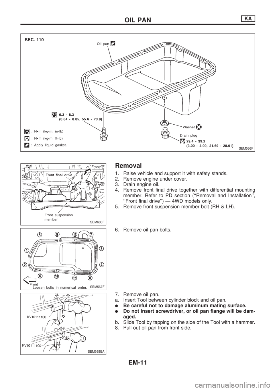
1. Raise vehicle and support it with safety stands.
2. Remove engine under cover.
3. Drain engine oil.
4. Remove front final drive together with differential mounting
member. Refer to PD section (``Removal and Installation'',
``Front final drive'') Ð 4WD models only.
5. Remove front suspension member bolt (RH & LH).
6. Remove oil pan bolts.
7. Remove oil pan.
a. Insert Tool between cylinder block and oil pan.
lBe careful not to damage aluminum mating surface.
lDo not insert screwdriver, or oil pan flange will be dam-
aged.
b. Slide Tool by tapping on the side of the Tool with a hammer.
8. Pull out oil pan from front side.
SEM566F
SEM600F
SEM567F
SEM365EA
OIL PANKA
EM-11
Page 697 of 1659
Removal
Removal order and pointsApplied model
2WD 4WD
1 Remove undercover.jj
2 Drain engine oil.jj
3Remove front propeller shaft
from front differential carrier.Ðj
4Remove front drive shaft fix-
ing bolts (RH & LH).Ðj
5Remove front suspension
crossmember.jj
6Remove differential front
mounting bolts (RH & LH)
and rear mounting bolts.Ðj
7Remove front differential car-
rier.ÐjRemoval order and pointsApplied model
2WD 4WD
8Remove front differential car-
rier mounting bracket.Ðj
9Remove transmission to rear
engine mounting bracket
nuts (RH & LH).jj
10Remove engine mounting
bolts or nuts (RH & LH).jj
11Lift up engine.
If necessary, disconnect
exhaust tube.jj
12 Remove oil pan.jj
WARNING:
lPlace vehicle on a flat and solid surface.
lPlace chocks at front and rear of rear wheels.
lYou should not remove oil pan until exhaust system and
cooling system have completely cooled off.
Otherwise, you may burn yourself and/or fire may break
out in the fuel line.
lWhen removing front and/or rear engine mounting bolts
or nuts, lift up slightly engine for safety work.
CAUTION:
lIn lifting engine, be careful not to hit against adjacent
parts, especially against accelerator wire casing end,
brake tube and brake master cylinder.
lFor tightening torque, refer to EM-71, MT and PD sec-
tions.
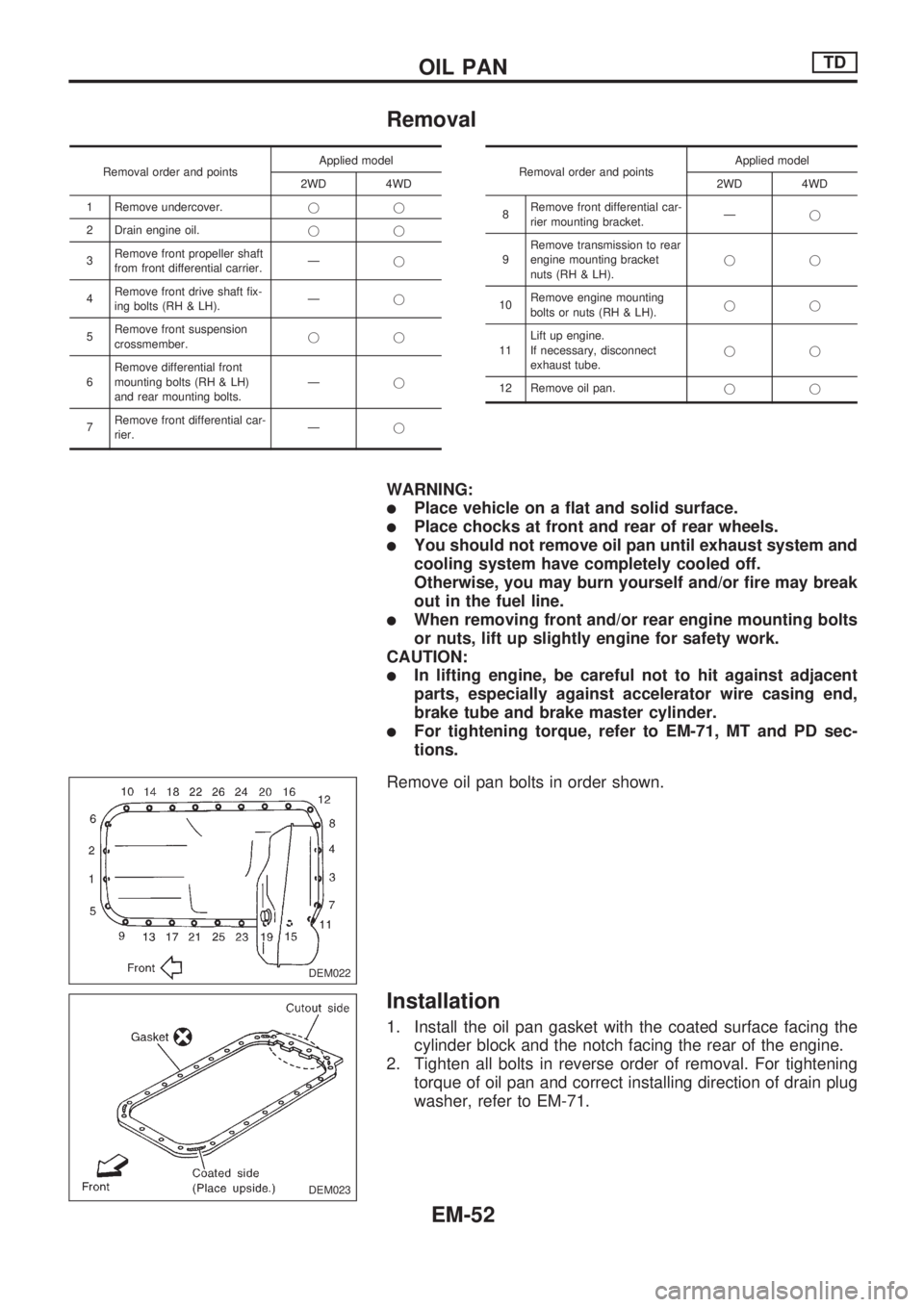
Remove oil pan bolts in order shown.
Installation
1. Install the oil pan gasket with the coated surface facing the
cylinder block and the notch facing the rear of the engine.
2. Tighten all bolts in reverse order of removal. For tightening
torque of oil pan and correct installing direction of drain plug
washer, refer to EM-71.
DEM022
DEM023
OIL PANTD
EM-52
Page 765 of 1659
FRONT AXLE &
FRONT SUSPENSION
SECTION
FA
CONTENTS
PRECAUTIONS AND PREPARATION..................... 1
Precautions ............................................................ 1
Special Service Tools ............................................ 1
Commercial Service Tools ..................................... 2
FRONT AXLE AND FRONT SUSPENSION............. 3
ON-VEHICLE SERVICE............................................ 5
Front Axle and Front Suspension Parts ................ 5
Front Wheel Bearing .............................................. 5
Front Wheel Alignment .......................................... 7
Drive Shaft ........................................................... 11
FRONT AXLE.......................................................... 12
Manual-lock Free-running Hub - 4WD - .............. 14
Auto-lock Free-running Hub - 4WD -................... 15
Removal ............................................................... 15
Installation ............................................................ 15Wheel Hub and Rotor Disc .................................. 16
Knuckle Spindle ................................................... 18
Drive Shaft - 4WD - ............................................. 21
FRONT SUSPENSION............................................ 26
Shock Absorber ................................................... 28
Torsion Bar Spring ............................................... 28
Stabilizer Bar........................................................ 31
Upper Link............................................................ 31
Tension Rod......................................................... 33
Lower Link............................................................ 33
Upper Ball Joint and Lower Ball Joint ................. 34
SERVICE DATA AND SPECIFICATIONS (SDS)... 35
General Specifications ......................................... 35
Inspection and Adjustment .................................. 35
FA
Page 766 of 1659
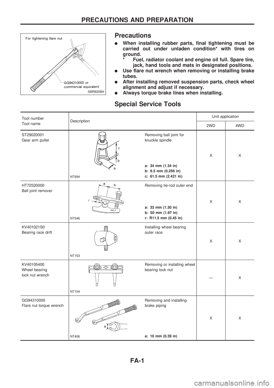
Precautions
lWhen installing rubber parts, final tightening must be
carried out under unladen condition* with tires on
ground.
* Fuel, radiator coolant and engine oil full. Spare tire,
jack, hand tools and mats in designated positions.
lUse flare nut wrench when removing or installing brake
tubes.
lAfter installing removed suspension parts, check wheel
alignment and adjust if necessary.
lAlways torque brake lines when installing.
Special Service Tools
Tool number
Tool nameDescriptionUnit application
2WD 4WD
ST29020001
Gear arm puller
NT694
Removing ball joint for
knuckle spindle
XX
a: 34 mm (1.34 in)
b: 6.5 mm (0.256 in)
c: 61.5 mm (2.421 in)
HT72520000
Ball joint remover
NT546
Removing tie-rod outer end
XX
a: 33 mm (1.30 in)
b: 50 mm (1.97 in)
r: R11.5 mm (0.45 in)
KV401021S0
Bearing race drift
NT153
Installing wheel bearing
outer race
XX
KV40105400
Wheel bearing
lock nut wrench
NT154
Removing or installing wheel
bearing lock nut
ÐX
GG94310000
Flare nut torque wrench
NT406
Removing and installing
brake piping
XX
a: 10 mm (0.39 in)
SBR820BA
PRECAUTIONS AND PREPARATION
FA-1
Page 768 of 1659
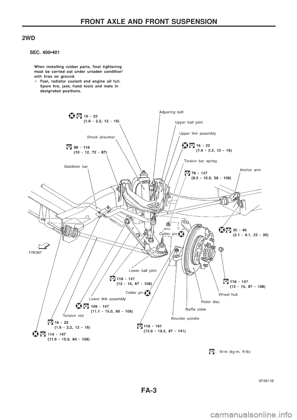
2WD
SFA811B
FRONT AXLE AND FRONT SUSPENSION
FA-3
Page 769 of 1659
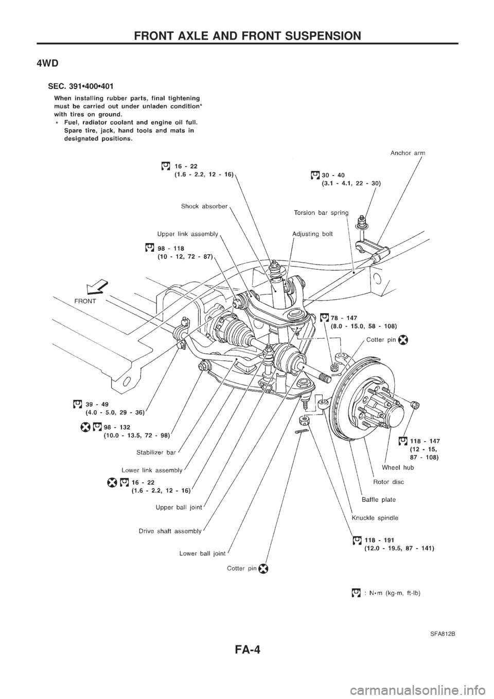
4WD
SFA812B
FRONT AXLE AND FRONT SUSPENSION
FA-4
Page 770 of 1659
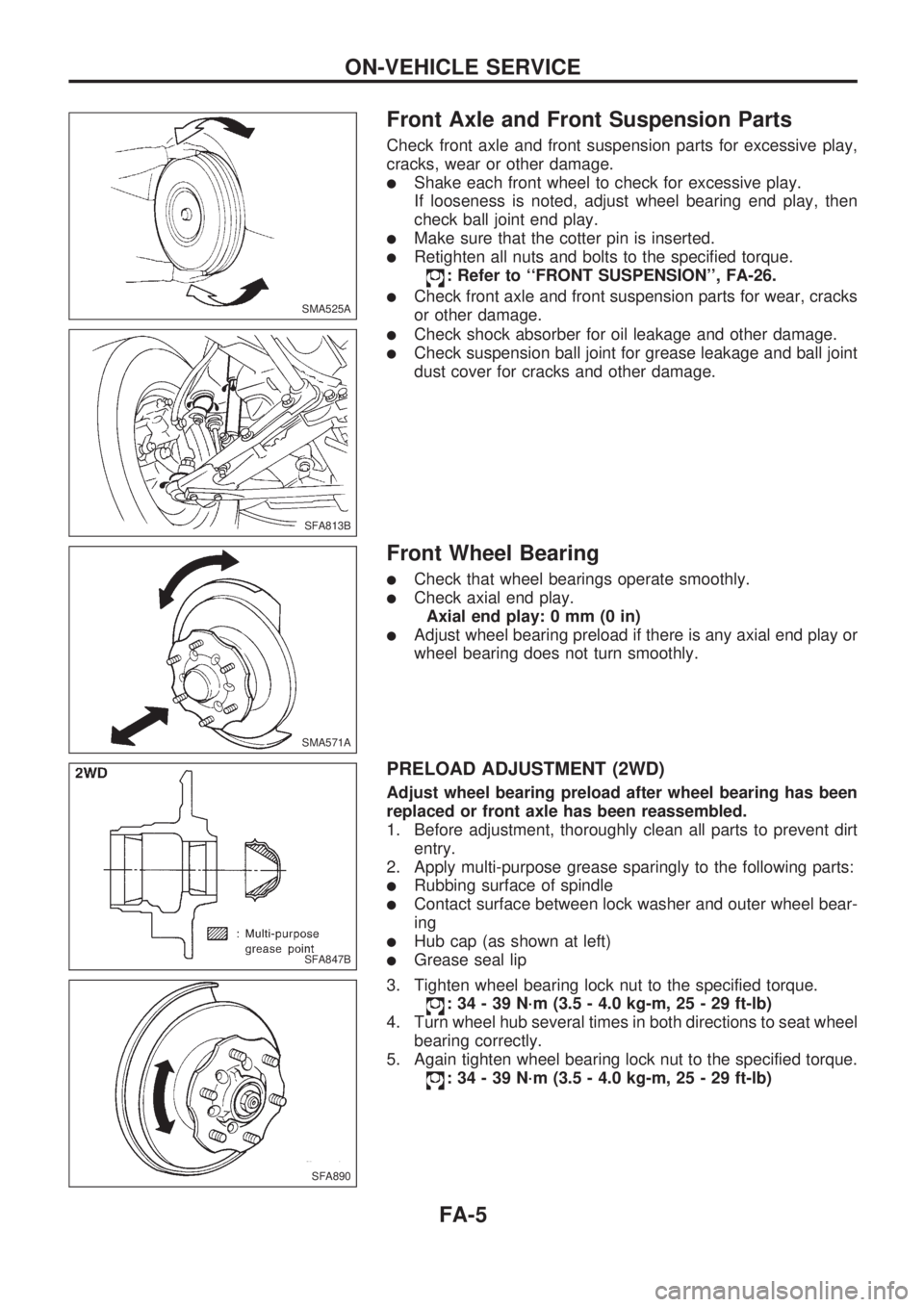
Front Axle and Front Suspension Parts
Check front axle and front suspension parts for excessive play,
cracks, wear or other damage.
lShake each front wheel to check for excessive play.
If looseness is noted, adjust wheel bearing end play, then
check ball joint end play.
lMake sure that the cotter pin is inserted.
lRetighten all nuts and bolts to the specified torque.
: Refer to ``FRONT SUSPENSION'', FA-26.
lCheck front axle and front suspension parts for wear, cracks
or other damage.
lCheck shock absorber for oil leakage and other damage.
lCheck suspension ball joint for grease leakage and ball joint
dust cover for cracks and other damage.
Front Wheel Bearing
lCheck that wheel bearings operate smoothly.
lCheck axial end play.
Axial end play: 0 mm (0 in)
lAdjust wheel bearing preload if there is any axial end play or
wheel bearing does not turn smoothly.
PRELOAD ADJUSTMENT (2WD)
Adjust wheel bearing preload after wheel bearing has been
replaced or front axle has been reassembled.
1. Before adjustment, thoroughly clean all parts to prevent dirt
entry.
2. Apply multi-purpose grease sparingly to the following parts:
lRubbing surface of spindle
lContact surface between lock washer and outer wheel bear-
ing
lHub cap (as shown at left)
lGrease seal lip
3. Tighten wheel bearing lock nut to the specified torque.
: 34 - 39 N´m (3.5 - 4.0 kg-m, 25 - 29 ft-lb)
4. Turn wheel hub several times in both directions to seat wheel
bearing correctly.
5. Again tighten wheel bearing lock nut to the specified torque.
: 34 - 39 N´m (3.5 - 4.0 kg-m, 25 - 29 ft-lb)
SMA525A
SFA813B
SMA571A
SFA847B
SFA890
ON-VEHICLE SERVICE
FA-5
Page 772 of 1659
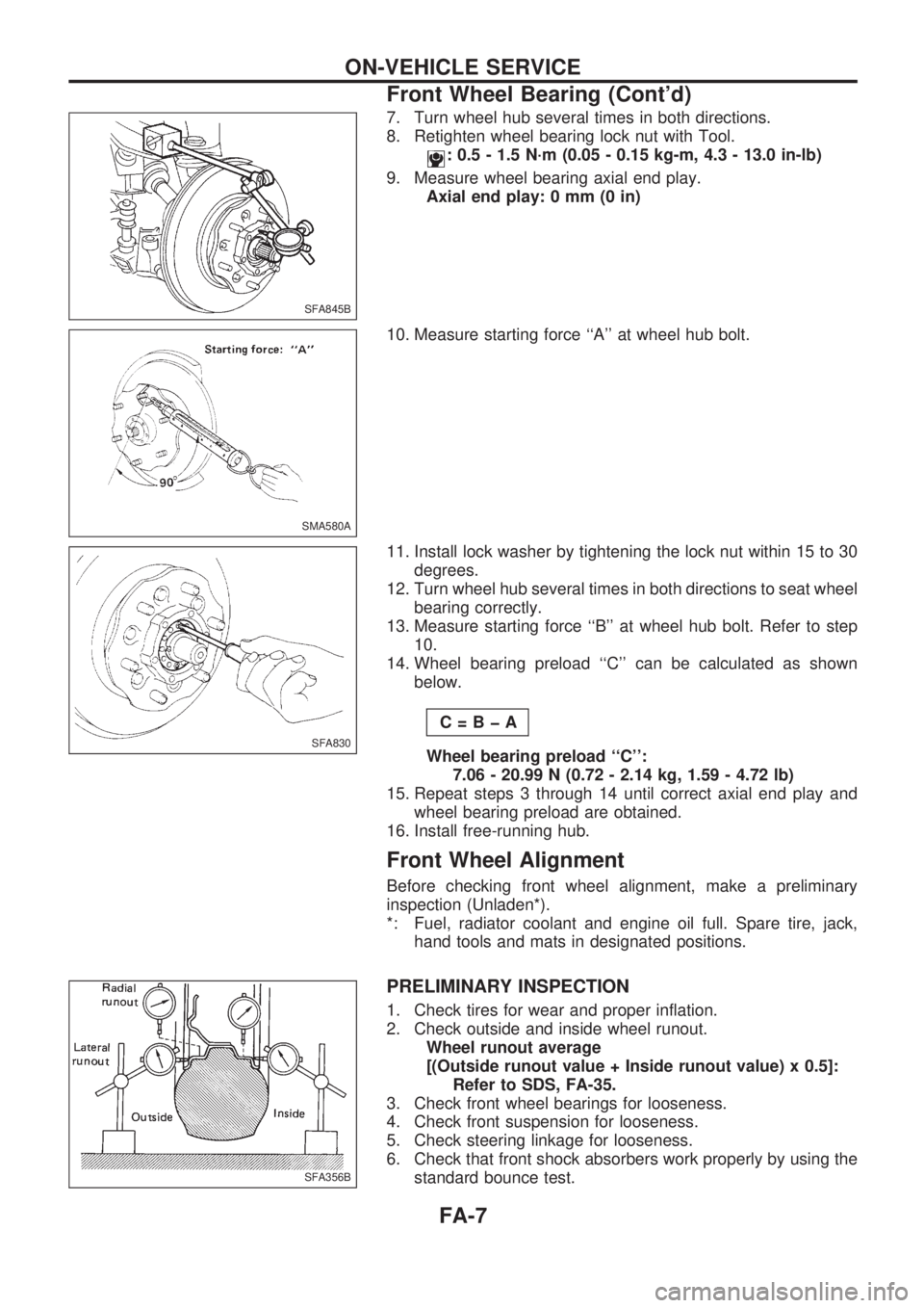
7. Turn wheel hub several times in both directions.
8. Retighten wheel bearing lock nut with Tool.
: 0.5 - 1.5 N´m (0.05 - 0.15 kg-m, 4.3 - 13.0 in-lb)
9. Measure wheel bearing axial end play.
Axial end play: 0 mm (0 in)
10. Measure starting force ``A'' at wheel hub bolt.
11. Install lock washer by tightening the lock nut within 15 to 30
degrees.
12. Turn wheel hub several times in both directions to seat wheel
bearing correctly.
13. Measure starting force ``B'' at wheel hub bolt. Refer to step
10.
14. Wheel bearing preload ``C'' can be calculated as shown
below.
C=BþA
Wheel bearing preload ``C'':
7.06 - 20.99 N (0.72 - 2.14 kg, 1.59 - 4.72 lb)
15. Repeat steps 3 through 14 until correct axial end play and
wheel bearing preload are obtained.
16. Install free-running hub.
Front Wheel Alignment
Before checking front wheel alignment, make a preliminary
inspection (Unladen*).
*: Fuel, radiator coolant and engine oil full. Spare tire, jack,
hand tools and mats in designated positions.
PRELIMINARY INSPECTION
1. Check tires for wear and proper inflation.
2. Check outside and inside wheel runout.
Wheel runout average
[(Outside runout value + Inside runout value) x 0.5]:
Refer to SDS, FA-35.
3. Check front wheel bearings for looseness.
4. Check front suspension for looseness.
5. Check steering linkage for looseness.
6. Check that front shock absorbers work properly by using the
standard bounce test.
SFA845B
SMA580A
SFA830
SFA356B
ON-VEHICLE SERVICE
Front Wheel Bearing (Cont'd)
FA-7
Page 773 of 1659
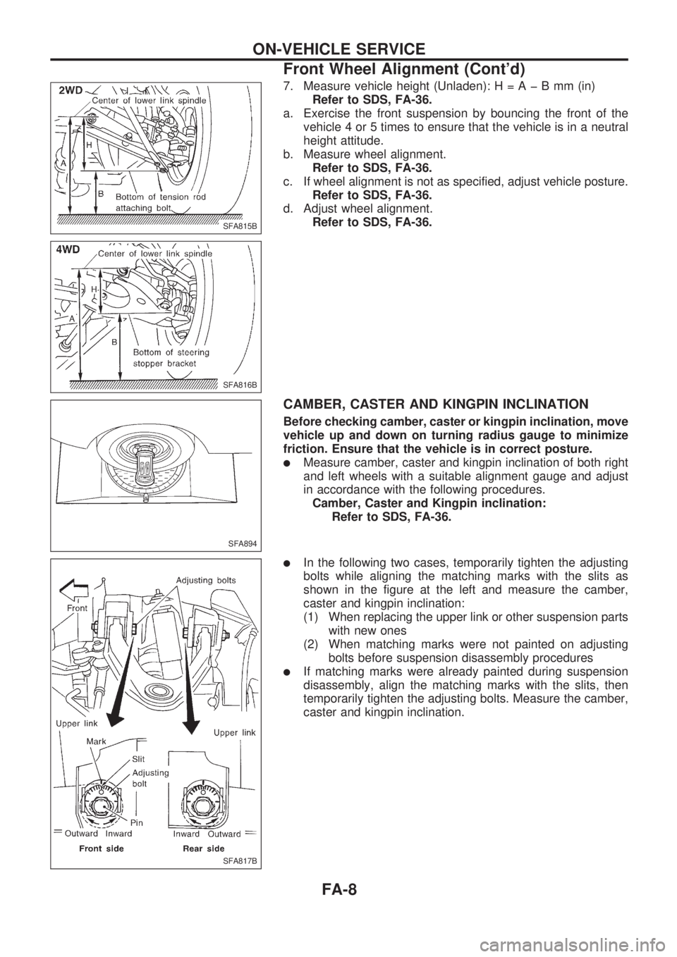
7. Measure vehicle height (Unladen):H=AþBmm(in)
Refer to SDS, FA-36.
a. Exercise the front suspension by bouncing the front of the
vehicle 4 or 5 times to ensure that the vehicle is in a neutral
height attitude.
b. Measure wheel alignment.
Refer to SDS, FA-36.
c. If wheel alignment is not as specified, adjust vehicle posture.
Refer to SDS, FA-36.
d. Adjust wheel alignment.
Refer to SDS, FA-36.
CAMBER, CASTER AND KINGPIN INCLINATION
Before checking camber, caster or kingpin inclination, move
vehicle up and down on turning radius gauge to minimize
friction. Ensure that the vehicle is in correct posture.
lMeasure camber, caster and kingpin inclination of both right
and left wheels with a suitable alignment gauge and adjust
in accordance with the following procedures.
Camber, Caster and Kingpin inclination:
Refer to SDS, FA-36.
lIn the following two cases, temporarily tighten the adjusting
bolts while aligning the matching marks with the slits as
shown in the figure at the left and measure the camber,
caster and kingpin inclination:
(1) When replacing the upper link or other suspension parts
with new ones
(2) When matching marks were not painted on adjusting
bolts before suspension disassembly procedures
lIf matching marks were already painted during suspension
disassembly, align the matching marks with the slits, then
temporarily tighten the adjusting bolts. Measure the camber,
caster and kingpin inclination.
SFA815B
SFA816B
SFA894
SFA817B
ON-VEHICLE SERVICE
Front Wheel Alignment (Cont'd)
FA-8