tire type NISSAN PICK-UP 1998 Repair Manual
[x] Cancel search | Manufacturer: NISSAN, Model Year: 1998, Model line: PICK-UP, Model: NISSAN PICK-UP 1998Pages: 1659, PDF Size: 53.39 MB
Page 439 of 1659

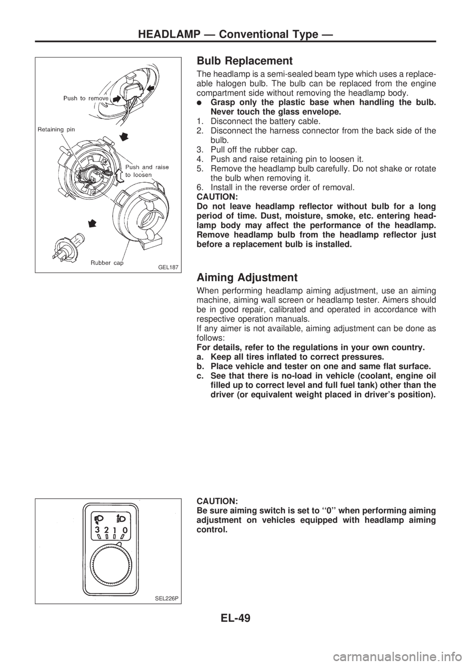
Bulb Replacement
The headlamp is a semi-sealed beam type which uses a replace-
able halogen bulb. The bulb can be replaced from the engine
compartment side without removing the headlamp body.
lGrasp only the plastic base when handling the bulb.
Never touch the glass envelope.
1. Disconnect the battery cable.
2. Disconnect the harness connector from the back side of the
bulb.
3. Pull off the rubber cap.
4. Push and raise retaining pin to loosen it.
5. Remove the headlamp bulb carefully. Do not shake or rotate
the bulb when removing it.
6. Install in the reverse order of removal.
CAUTION:
Do not leave headlamp reflector without bulb for a long
period of time. Dust, moisture, smoke, etc. entering head-
lamp body may affect the performance of the headlamp.
Remove headlamp bulb from the headlamp reflector just
before a replacement bulb is installed.
Aiming Adjustment
When performing headlamp aiming adjustment, use an aiming
machine, aiming wall screen or headlamp tester. Aimers should
be in good repair, calibrated and operated in accordance with
respective operation manuals.
If any aimer is not available, aiming adjustment can be done as
follows:
For details, refer to the regulations in your own country.
a. Keep all tires inflated to correct pressures.
b. Place vehicle and tester on one and same flat surface.
c. See that there is no-load in vehicle (coolant, engine oil
filled up to correct level and full fuel tank) other than the
driver (or equivalent weight placed in driver's position).
CAUTION:
Be sure aiming switch is set to ``0'' when performing aiming
adjustment on vehicles equipped with headlamp aiming
control.
GEL187
SEL226P
HEADLAMP Ð Conventional Type Ð
EL-49
Page 849 of 1659

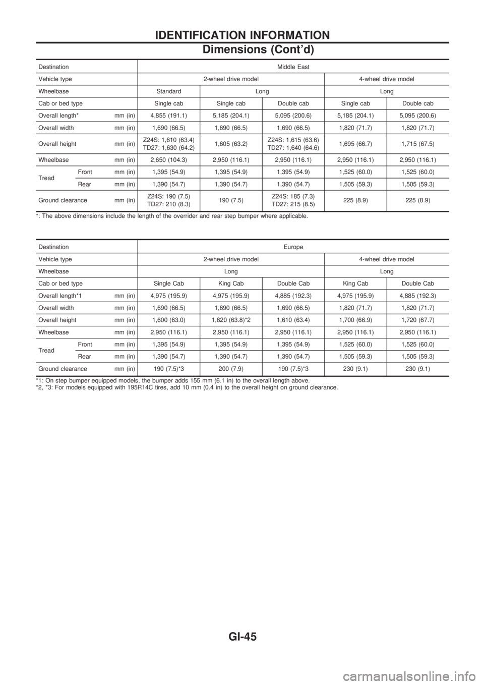
DestinationMiddle East
Vehicle type 2-wheel drive model 4-wheel drive model
Wheelbase Standard Long Long
Cab or bed type Single cab Single cab Double cab Single cab Double cab
Overall length* mm (in) 4,855 (191.1) 5,185 (204.1) 5,095 (200.6) 5,185 (204.1) 5,095 (200.6)
Overall width mm (in) 1,690 (66.5) 1,690 (66.5) 1,690 (66.5) 1,820 (71.7) 1,820 (71.7)
Overall height mm (in)Z24S: 1,610 (63.4)
TD27: 1,630 (64.2)1,605 (63.2)Z24S: 1,615 (63.6)
TD27: 1,640 (64.6)1,695 (66.7) 1,715 (67.5)
Wheelbase mm (in) 2,650 (104.3) 2,950 (116.1) 2,950 (116.1) 2,950 (116.1) 2,950 (116.1)
TreadFront mm (in) 1,395 (54.9) 1,395 (54.9) 1,395 (54.9) 1,525 (60.0) 1,525 (60.0)
Rear mm (in) 1,390 (54.7) 1,390 (54.7) 1,390 (54.7) 1,505 (59.3) 1,505 (59.3)
Ground clearance mm (in)Z24S: 190 (7.5)
TD27: 210 (8.3)190 (7.5)Z24S: 185 (7.3)
TD27: 215 (8.5)225 (8.9) 225 (8.9)
*: The above dimensions include the length of the overrider and rear step bumper where applicable.
DestinationEurope
Vehicle type 2-wheel drive model 4-wheel drive model
Wheelbase Long Long
Cab or bed type Single Cab King Cab Double Cab King Cab Double Cab
Overall length*1 mm (in) 4,975 (195.9) 4,975 (195.9) 4,885 (192.3) 4,975 (195.9) 4,885 (192.3)
Overall width mm (in) 1,690 (66.5) 1,690 (66.5) 1,690 (66.5) 1,820 (71.7) 1,820 (71.7)
Overall height mm (in) 1,600 (63.0) 1,620 (63.8)*2 1,610 (63.4) 1,700 (66.9) 1,720 (67.7)
Wheelbase mm (in) 2,950 (116.1) 2,950 (116.1) 2,950 (116.1) 2,950 (116.1) 2,950 (116.1)
TreadFront mm (in) 1,395 (54.9) 1,395 (54.9) 1,395 (54.9) 1,525 (60.0) 1,525 (60.0)
Rear mm (in) 1,390 (54.7) 1,390 (54.7) 1,390 (54.7) 1,505 (59.3) 1,505 (59.3)
Ground clearance mm (in) 190 (7.5)*3 200 (7.9) 190 (7.5)*3 230 (9.1) 230 (9.1)
*1: On step bumper equipped models, the bumper adds 155 mm (6.1 in) to the overall length above.
*2, *3: For models equipped with 195R14C tires, add 10 mm (0.4 in) to the overall height on ground clearance.
IDENTIFICATION INFORMATION
Dimensions (Cont'd)
GI-45
Page 1228 of 1659

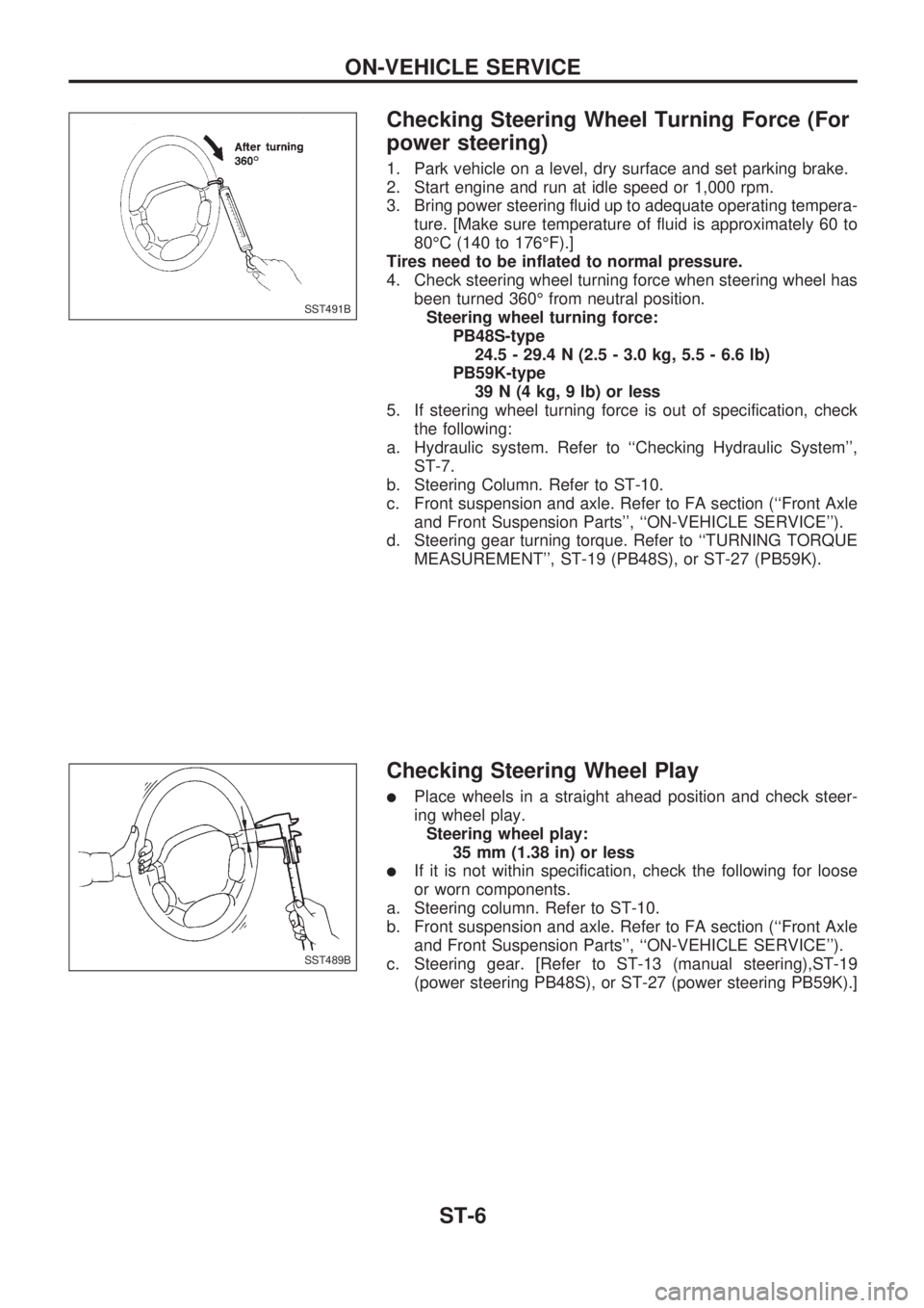
Checking Steering Wheel Turning Force (For
power steering)
1. Park vehicle on a level, dry surface and set parking brake.
2. Start engine and run at idle speed or 1,000 rpm.
3. Bring power steering fluid up to adequate operating tempera-
ture. [Make sure temperature of fluid is approximately 60 to
80ÉC (140 to 176ÉF).]
Tires need to be inflated to normal pressure.
4. Check steering wheel turning force when steering wheel has
been turned 360É from neutral position.
Steering wheel turning force:
PB48S-type
24.5 - 29.4 N (2.5 - 3.0 kg, 5.5 - 6.6 lb)
PB59K-type
39 N (4 kg, 9 lb) or less
5. If steering wheel turning force is out of specification, check
the following:
a. Hydraulic system. Refer to ``Checking Hydraulic System'',
ST-7.
b. Steering Column. Refer to ST-10.
c. Front suspension and axle. Refer to FA section (``Front Axle
and Front Suspension Parts'', ``ON-VEHICLE SERVICE'').
d. Steering gear turning torque. Refer to ``TURNING TORQUE
MEASUREMENT'', ST-19 (PB48S), or ST-27 (PB59K).
Checking Steering Wheel Play
lPlace wheels in a straight ahead position and check steer-
ing wheel play.
Steering wheel play:
35 mm (1.38 in) or less
lIf it is not within specification, check the following for loose
or worn components.
a. Steering column. Refer to ST-10.
b. Front suspension and axle. Refer to FA section (``Front Axle
and Front Suspension Parts'', ``ON-VEHICLE SERVICE'').
c. Steering gear. [Refer to ST-13 (manual steering),ST-19
(power steering PB48S), or ST-27 (power steering PB59K).]
SST491B
SST489B
ON-VEHICLE SERVICE
ST-6
Page 1347 of 1659

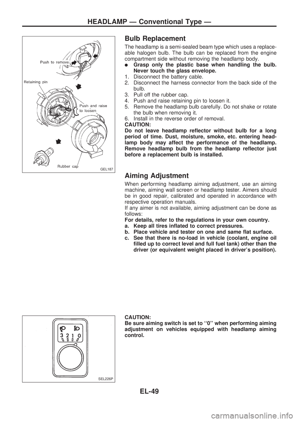
Bulb Replacement
The headlamp is a semi-sealed beam type which uses a replace-
able halogen bulb. The bulb can be replaced from the engine
compartment side without removing the headlamp body.
lGrasp only the plastic base when handling the bulb.
Never touch the glass envelope.
1. Disconnect the battery cable.
2. Disconnect the harness connector from the back side of the
bulb.
3. Pull off the rubber cap.
4. Push and raise retaining pin to loosen it.
5. Remove the headlamp bulb carefully. Do not shake or rotate
the bulb when removing it.
6. Install in the reverse order of removal.
CAUTION:
Do not leave headlamp reflector without bulb for a long
period of time. Dust, moisture, smoke, etc. entering head-
lamp body may affect the performance of the headlamp.
Remove headlamp bulb from the headlamp reflector just
before a replacement bulb is installed.
Aiming Adjustment
When performing headlamp aiming adjustment, use an aiming
machine, aiming wall screen or headlamp tester. Aimers should
be in good repair, calibrated and operated in accordance with
respective operation manuals.
If any aimer is not available, aiming adjustment can be done as
follows:
For details, refer to the regulations in your own country.
a. Keep all tires inflated to correct pressures.
b. Place vehicle and tester on one and same flat surface.
c. See that there is no-load in vehicle (coolant, engine oil
filled up to correct level and full fuel tank) other than the
driver (or equivalent weight placed in driver's position).
CAUTION:
Be sure aiming switch is set to ``0'' when performing aiming
adjustment on vehicles equipped with headlamp aiming
control.
GEL187
SEL226P
HEADLAMP Ð Conventional Type Ð
EL-49