torque NISSAN PICK-UP 1998 Repair Manual
[x] Cancel search | Manufacturer: NISSAN, Model Year: 1998, Model line: PICK-UP, Model: NISSAN PICK-UP 1998Pages: 1659, PDF Size: 53.39 MB
Page 5 of 1659
Supplemental Restraint System (SRS) ``AIR
BAG'' (4WD models)
The Supplemental Restraint System ``AIR BAG'', used along with a seat belt, helps to reduce the risk or
severity of injury to the driver in a frontal collision. The Supplemental Restraint System consists of air bag
module (located in the center of the steering wheel), a diagnosis sensor unit, warning lamp, wiring harness
and spiral cable. Information necessary to service the system safely is included in theRS sectionof this
Service Manual.
WARNING:
lTo avoid rendering the SRS inoperative, which could increase the risk of personal injury or death
in the event of a collision which would result in air bag inflation, all maintenance must be per-
formed by an authorized NISSAN dealer.
lImproper maintenance, including incorrect removal and installation of the SRS, can lead to per-
sonal injury caused by unintentional activation of the system.
lDo not use electrical test equipment on any circuit related to the SRS unless instructed to in this
Service Manual. SRS wiring harnesses are covered with yellow insulation either just before the
harness connectors or for the complete harness, for easy identification.
Supplemental Restraint System (SRS) ``AIR
BAG'' (2WD models)
The Supplemental Restraint System ``AIR BAG'', used along with a seat belt, helps to reduce the risk or
severity of injury to the driver in a frontal collision. The Supplemental Restraint System consists of an air
bag module (located in the center of the steering wheel), a diagnosis sensor unit, warning lamp and spiral
cable. Information necessary to service the system safely is included in theRS sectionof this Service
Manual.
WARNING:
lTo avoid rendering the SRS inoperative, which could increase the risk of personal injury or death
in the event of a collision which would result in air bag inflation, all maintenance must be per-
formed by an authorized NISSAN dealer.
lImproper maintenance, including incorrect removal and installation of the SRS, can lead to per-
sonal injury caused by unintentional activation of the system.
lDo not use electrical test equipment on any circuit related to the SRS.
Precautions for Brake System
lUse brake fluid DOT 3 or DOT 4*1.
lNever reuse drained brake fluid.
lBe careful not to splash brake fluid on painted areas; it
may cause paint damage. If brake fluid is splashed on
painted areas, wash it away with water immediately.
lTo clean master cylinder parts, disc brake caliper parts
or wheel cylinder parts, use clean brake fluid.
lNever use mineral oils such as gasoline or kerosene.
They will ruin rubber parts of the hydraulic system.
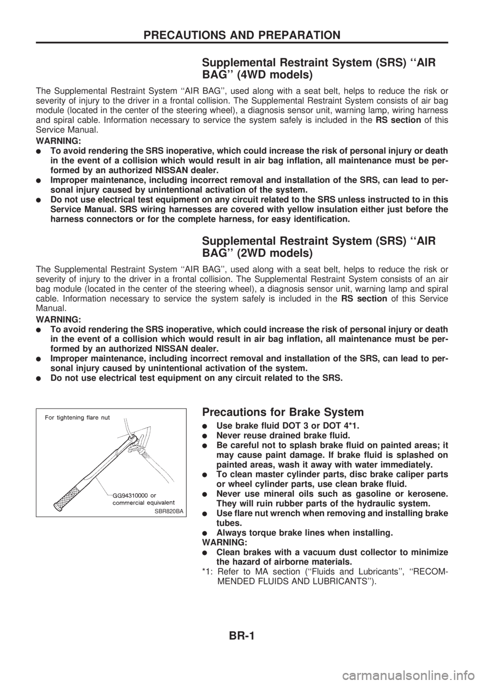
lUse flare nut wrench when removing and installing brake
tubes.
lAlways torque brake lines when installing.
WARNING:
lClean brakes with a vacuum dust collector to minimize
the hazard of airborne materials.
*1: Refer to MA section (``Fluids and Lubricants'', ``RECOM-
MENDED FLUIDS AND LUBRICANTS'').
SBR820BA
PRECAUTIONS AND PREPARATION
BR-1
Page 6 of 1659
Special Service Tools
Tool number
Tool nameDescription
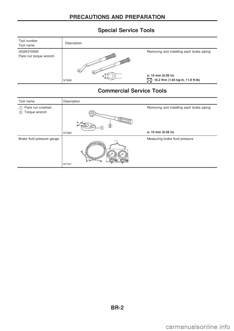
GG94310000
Flare nut torque wrench
NT406
Removing and installing each brake piping
a: 10 mm (0.39 in)
: 16.2 Nzm (1.65 kg-m, 11.9 ft-lb)
Commercial Service Tools
Tool name Description
V1Flare nut crowfoot
V2Torque wrench
NT360
Removing and installing each brake piping
a: 10 mm (0.39 in)
Brake fluid pressure gauge
NT151
Measuring brake fluid pressure
PRECAUTIONS AND PREPARATION
BR-2
Page 8 of 1659
Bleeding Brake System
CAUTION:
lCarefully monitor brake fluid level at master cylinder
during bleeding operation.
lIf master cylinder is suspected to have air inside, bleed
air from master cylinder first. Refer to ``Installation'',
``MASTER CYLINDER'', BR-14.
lFill reservoir with new brake fluid DOT 3 or DOT 4*1.
Make sure it is full at all times while bleeding air out of
system.
lPlace a container under master cylinder to avoid spillage
of brake fluid.
lFor models with ABS, turn ignition switch OFF and dis-
connect ABS actuator connector or battery cable.
lBleed air in the following order.
a. LSV air bleeder
b. Left rear brake
c. Right rear brake
d. Left front brake
e. Right front brake
*1: Refer to MA section (``Fluids and Lubricants'', ``RECOM-
MENDED FLUIDS AND LUBRICANTS'').
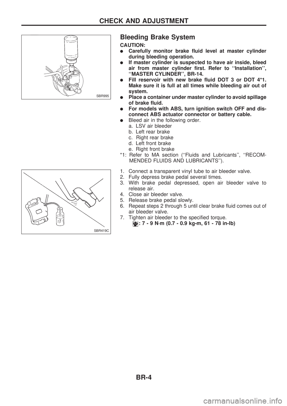
1. Connect a transparent vinyl tube to air bleeder valve.
2. Fully depress brake pedal several times.
3. With brake pedal depressed, open air bleeder valve to
release air.
4. Close air bleeder valve.
5. Release brake pedal slowly.
6. Repeat steps 2 through 5 until clear brake fluid comes out of
air bleeder valve.
7. Tighten air bleeder to the specified torque.
:7-9N´m(0.7 - 0.9 kg-m, 61 - 78 in-lb)
SBR995
SBR419C
CHECK AND ADJUSTMENT
BR-4
Page 26 of 1659
Removal
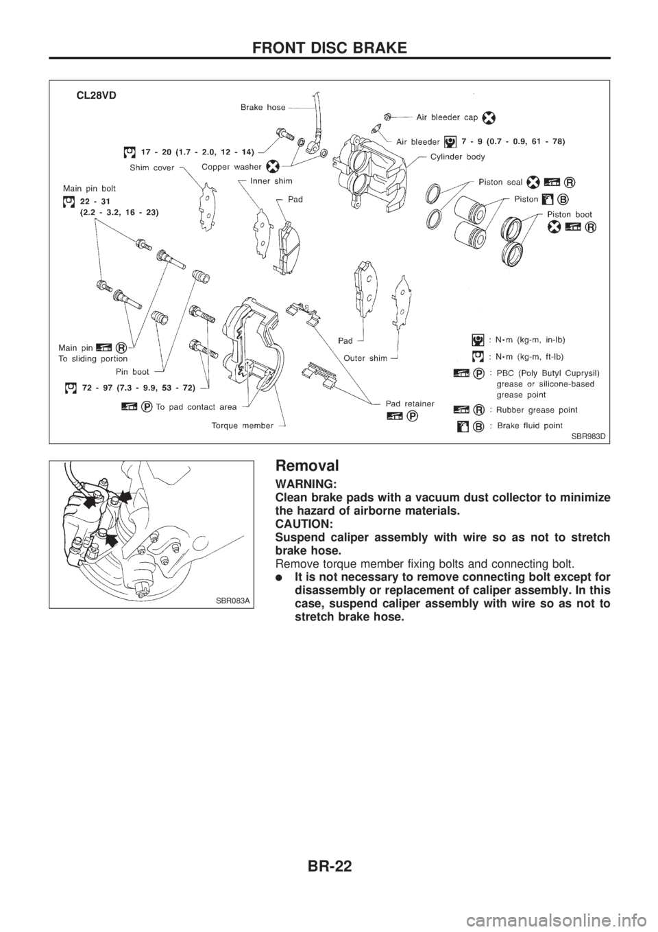
WARNING:
Clean brake pads with a vacuum dust collector to minimize
the hazard of airborne materials.
CAUTION:
Suspend caliper assembly with wire so as not to stretch
brake hose.
Remove torque member fixing bolts and connecting bolt.
lIt is not necessary to remove connecting bolt except for
disassembly or replacement of caliper assembly. In this
case, suspend caliper assembly with wire so as not to
stretch brake hose.
SBR983D
SBR083A
FRONT DISC BRAKE
BR-22
Page 86 of 1659
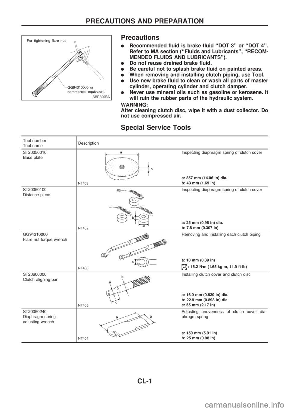
Precautions
lRecommended fluid is brake fluid ``DOT 3'' or ``DOT 4''.
Refer to MA section (``Fluids and Lubricants'', ``RECOM-
MENDED FLUIDS AND LUBRICANTS'').
lDo not reuse drained brake fluid.
lBe careful not to splash brake fluid on painted areas.
lWhen removing and installing clutch piping, use Tool.
lUse new brake fluid to clean or wash all parts of master
cylinder, operating cylinder and clutch damper.
lNever use mineral oils such as gasoline or kerosene. It
will ruin the rubber parts of the hydraulic system.
WARNING:
After cleaning clutch disc, wipe it with a dust collector. Do
not use compressed air.
Special Service Tools
Tool number
Tool nameDescription
ST20050010
Base plate
NT403
Inspecting diaphragm spring of clutch cover
a: 357 mm (14.06 in) dia.
b: 43 mm (1.69 in)
ST20050100
Distance piece
NT402
Inspecting diaphragm spring of clutch cover
a: 25 mm (0.98 in) dia.
b: 7.8 mm (0.307 in)
GG94310000
Flare nut torque wrench
NT406
Removing and installing each clutch piping
a: 10 mm (0.39 in)
: 16.2 Nzm (1.65 kg-m, 11.9 ft-lb)
ST20600000
Clutch aligning bar
NT405
Installing clutch cover and clutch disc
a: 16.0 mm (0.630 in) dia.
b: 22.8 mm (0.898 in) dia.
c: 55 mm (2.17 in)
ST20050240
Diaphragm spring
adjusting wrench
NT404
Adjusting unevenness of clutch cover dia-
phragm spring
a: 150 mm (5.91 in)
b: 25 mm (0.98 in)
SBR820BA
PRECAUTIONS AND PREPARATION
CL-1
Page 87 of 1659
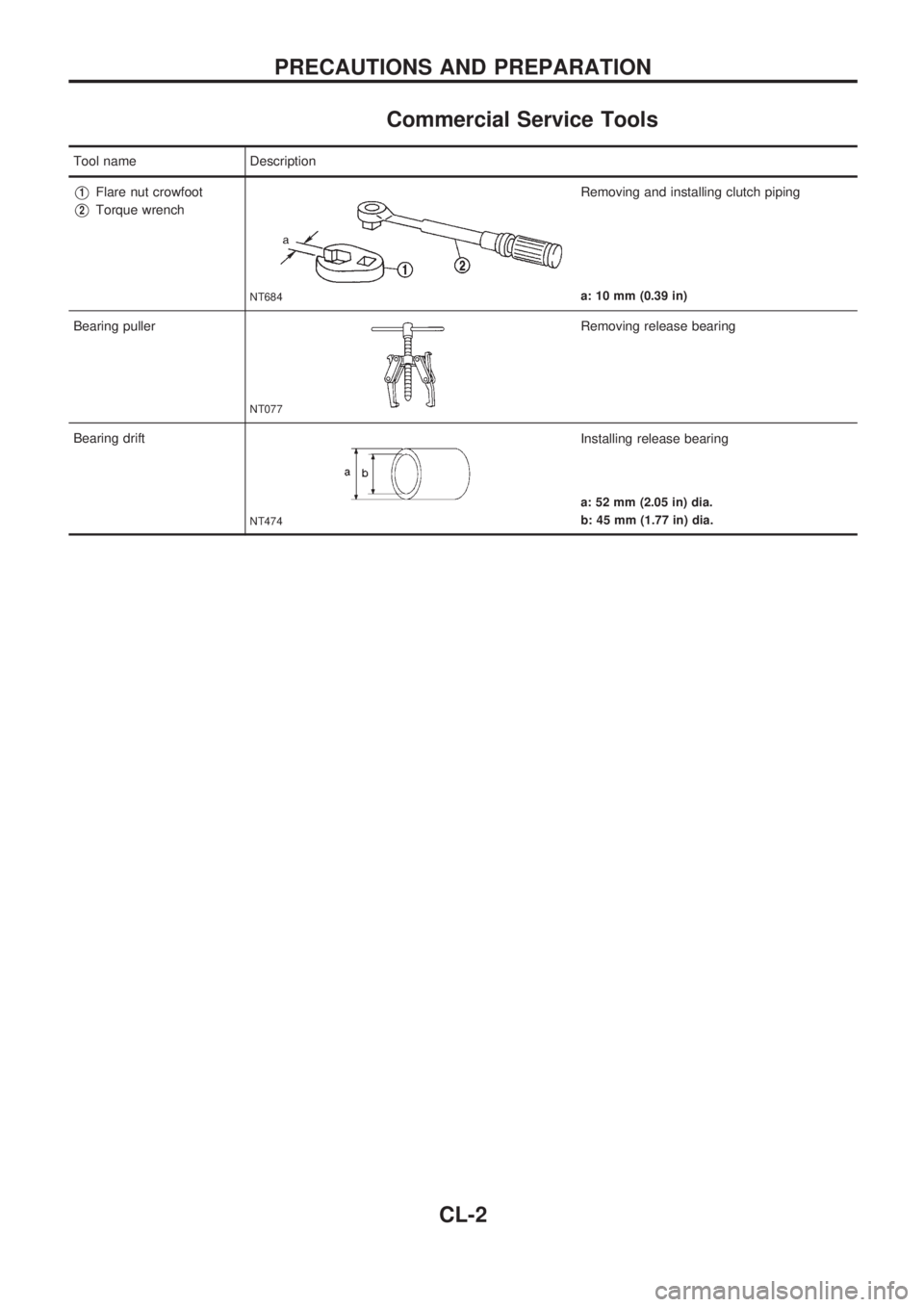
Commercial Service Tools
Tool name Description
V1Flare nut crowfoot
V2Torque wrench
NT684
Removing and installing clutch piping
a: 10 mm (0.39 in)
Bearing puller
NT077
Removing release bearing
Bearing drift
NT474
Installing release bearing
a: 52 mm (2.05 in) dia.
b: 45 mm (1.77 in) dia.
PRECAUTIONS AND PREPARATION
CL-2
Page 174 of 1659
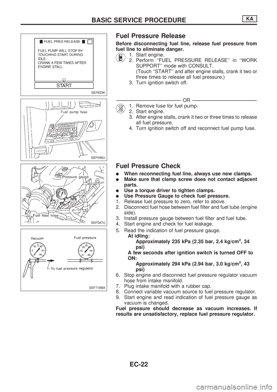
Fuel Pressure Release
Before disconnecting fuel line, release fuel pressure from
fuel line to eliminate danger.
1. Start engine.
2. Perform ``FUEL PRESSURE RELEASE'' in ``WORK
SUPPORT'' mode with CONSULT.
(Touch ``START'' and after engine stalls, crank it two or
three times to release all fuel pressure.)
3. Turn ignition switch off.
-------------------------------------------------------------------------------------------------------------------------------------------------------------------------------------------------------------------------------------------------OR-------------------------------------------------------------------------------------------------------------------------------------------------------------------------------------------------------------------------------------------------
1. Remove fuse for fuel pump.
2. Start engine.
3. After engine stalls, crank it two or three times to release
all fuel pressure.
4. Turn ignition switch off and reconnect fuel pump fuse.
Fuel Pressure Check
lWhen reconnecting fuel line, always use new clamps.
lMake sure that clamp screw does not contact adjacent
parts.
lUse a torque driver to tighten clamps.
lUse Pressure Gauge to check fuel pressure.
1. Release fuel pressure to zero, refer to above.
2. Disconnect fuel hose between fuel filter and fuel tube (engine
side).
3. Install pressure gauge between fuel filter and fuel tube.
4. Start engine and check for fuel leakage.
5. Read the indication of fuel pressure gauge.
At idling:
Approximately 235 kPa (2.35 bar, 2.4 kg/cm
2,34
psi)
A few seconds after ignition switch is turned OFF to
ON:
Approximately 294 kPa (2.94 bar, 3.0 kg/cm
2,43
psi)
6. Stop engine and disconnect fuel pressure regulator vacuum
hose from intake manifold.
7. Plug intake manifold with a rubber cap.
8. Connect variable vacuum source to fuel pressure regulator.
9. Start engine and read indication of fuel pressure gauge as
vacuum is changed.
Fuel pressure should decrease as vacuum increases. If
results are unsatisfactory, replace fuel pressure regulator.
SEF823K
SEF046U
SEF047U
SEF718BA
BASIC SERVICE PROCEDUREKA
EC-22
Page 344 of 1659
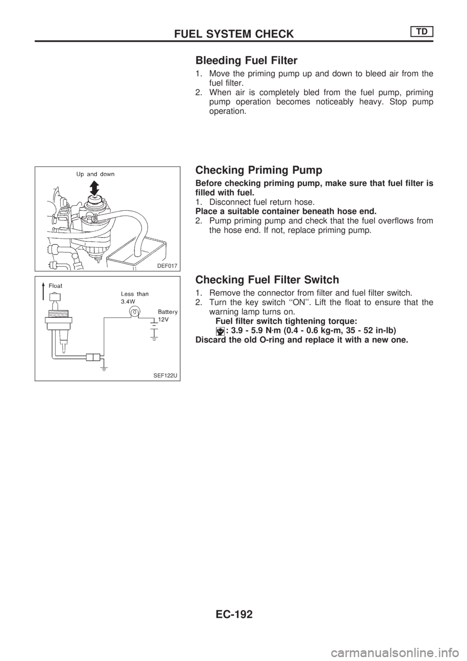
Bleeding Fuel Filter
1. Move the priming pump up and down to bleed air from the
fuel filter.
2. When air is completely bled from the fuel pump, priming
pump operation becomes noticeably heavy. Stop pump
operation.
Checking Priming Pump
Before checking priming pump, make sure that fuel filter is
filled with fuel.
1. Disconnect fuel return hose.
Place a suitable container beneath hose end.
2. Pump priming pump and check that the fuel overflows from
the hose end. If not, replace priming pump.
Checking Fuel Filter Switch
1. Remove the connector from filter and fuel filter switch.
2. Turn the key switch ``ON''. Lift the float to ensure that the
warning lamp turns on.
Fuel filter switch tightening torque:
: 3.9 - 5.9 Nzm (0.4 - 0.6 kg-m, 35 - 52 in-lb)
Discard the old O-ring and replace it with a new one.
DEF017
SEF122U
FUEL SYSTEM CHECKTD
EC-192
Page 426 of 1659
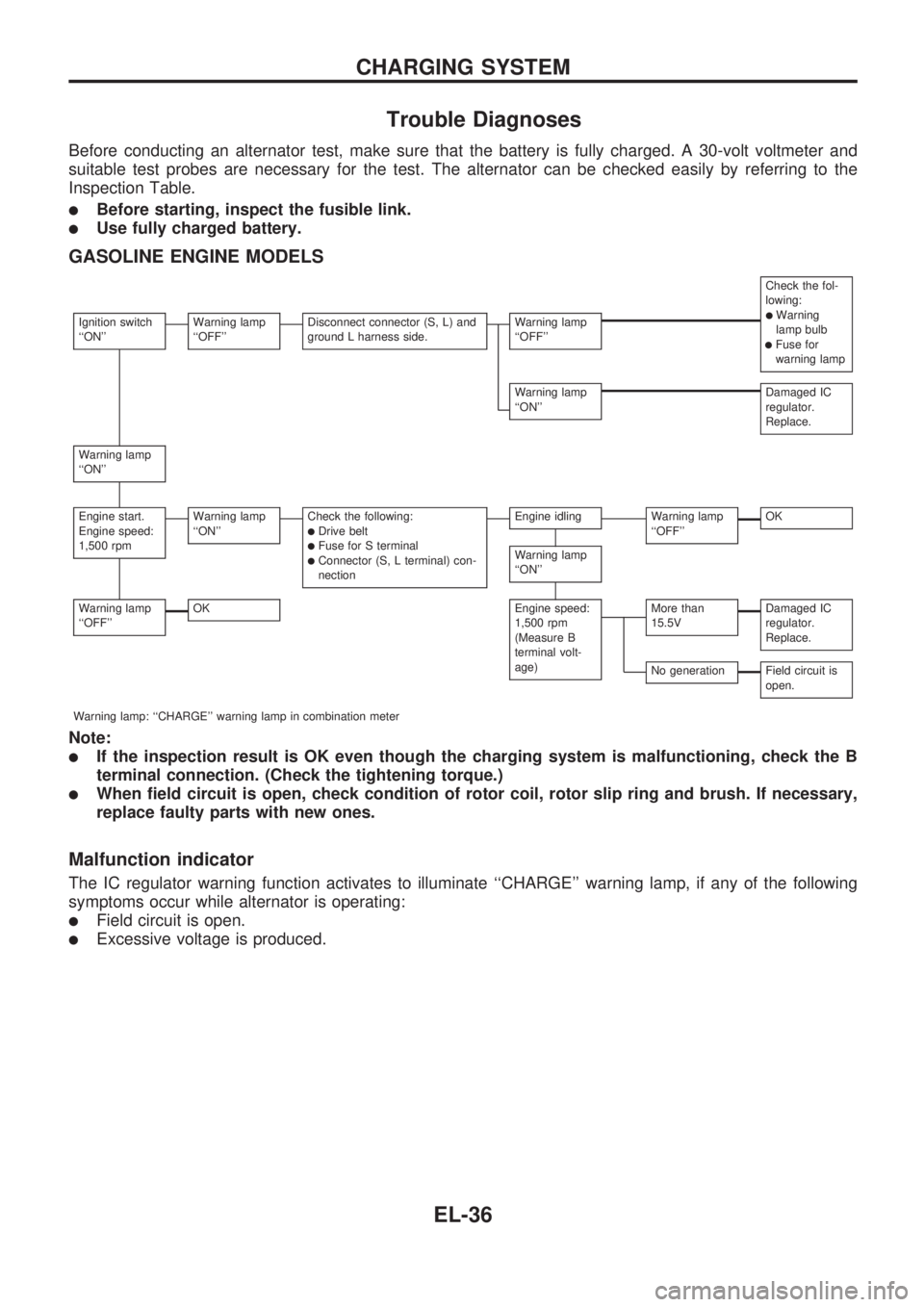
Trouble Diagnoses
Before conducting an alternator test, make sure that the battery is fully charged. A 30-volt voltmeter and
suitable test probes are necessary for the test. The alternator can be checked easily by referring to the
Inspection Table.
lBefore starting, inspect the fusible link.
lUse fully charged battery.
GASOLINE ENGINE MODELS
Check the fol-
lowing:
lWarning
lamp bulb
lFuse for
warning lamp
Ignition switch
``ON''Warning lamp
``OFF''Disconnect connector (S, L) and
ground L harness side.Warning lamp
``OFF''
Warning lamp
``ON''Damaged IC
regulator.
Replace.
Warning lamp
``ON''
Engine start.
Engine speed:
1,500 rpmWarning lamp
``ON''Check the following:lDrive beltlFuse for S terminallConnector (S, L terminal) con-
nection
Engine idlingWarning lamp
``OFF''OK
Warning lamp
``ON''
Warning lamp
``OFF''OKEngine speed:
1,500 rpm
(Measure B
terminal volt-
age)More than
15.5VDamaged IC
regulator.
Replace.
No generationField circuit is
open.
Warning lamp: ``CHARGE'' warning lamp in combination meter
Note:
lIf the inspection result is OK even though the charging system is malfunctioning, check the B
terminal connection. (Check the tightening torque.)
lWhen field circuit is open, check condition of rotor coil, rotor slip ring and brush. If necessary,
replace faulty parts with new ones.
Malfunction indicator
The IC regulator warning function activates to illuminate ``CHARGE'' warning lamp, if any of the following
symptoms occur while alternator is operating:
lField circuit is open.
lExcessive voltage is produced.
CHARGING SYSTEM
EL-36
Page 427 of 1659
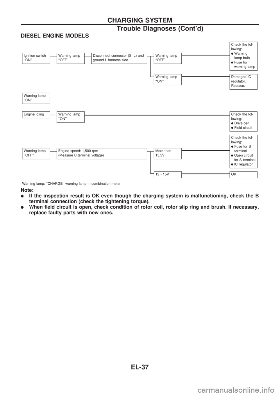
DIESEL ENGINE MODELS
Check the fol-
lowing:
lWarning
lamp bulb
lFuse for
warning lamp
Ignition switch
``ON''Warning lamp
``OFF''Disconnect connector (S, L) and
ground L harness side.Warning lamp
``OFF''
Warning lamp
``ON''Damaged IC
regulator.
Replace.
Warning lamp
``ON''
Engine idlingWarning lamp
``ON''Check the fol-
lowing:
lDrive beltlField circuit
Check the fol-
lowing:
lFuse for S
terminal
lOpen circuit
for S terminal
lIC regulator
Warning lamp
``OFF''Engine speed: 1,500 rpm
(Measure B terminal voltage)More than
15.5V
13 - 15VOK
Warning lamp: ``CHARGE'' warning lamp in combination meter
Note:
lIf the inspection result is OK even though the charging system is malfunctioning, check the B
terminal connection (check the tightening torque).
lWhen field circuit is open, check condition of rotor coil, rotor slip ring and brush. If necessary,
replace faulty parts with new ones.
CHARGING SYSTEM
Trouble Diagnoses (Cont'd)
EL-37