battery location NISSAN PICK-UP 1998 Repair Manual
[x] Cancel search | Manufacturer: NISSAN, Model Year: 1998, Model line: PICK-UP, Model: NISSAN PICK-UP 1998Pages: 1659, PDF Size: 53.39 MB
Page 538 of 1659
Power Antenna
TROUBLE DIAGNOSES
Symptom Possible causes Repair order
Power antenna does not oper-
ate.1. 7.5A fuse
2. Radio signal
3. Grounds
E6andE39
1. Check 7.5A fuse (No.6, located in fuse block). Verify that
battery positive voltage is present at terminal
V1of power
antenna.
2. Turn ignition switch and radio ON. Verify that battery positive
voltage is present at terminal
V3of power antenna.
3. Check groundsE6andE39.
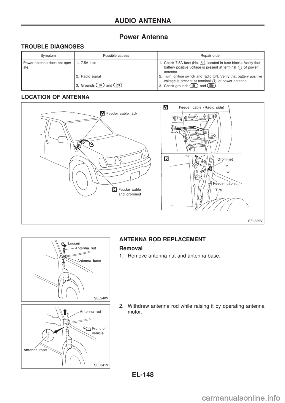
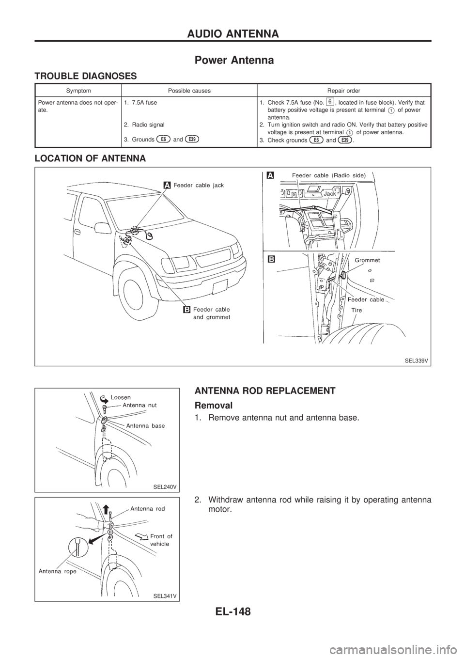
LOCATION OF ANTENNA
ANTENNA ROD REPLACEMENT
Removal
1. Remove antenna nut and antenna base.
2. Withdraw antenna rod while raising it by operating antenna
motor.
SEL339V
SEL240V
SEL341V
AUDIO ANTENNA
EL-148
Page 807 of 1659
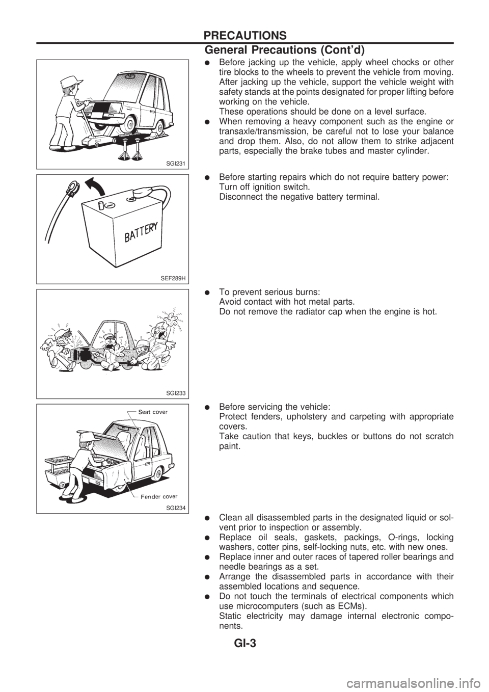
lBefore jacking up the vehicle, apply wheel chocks or other
tire blocks to the wheels to prevent the vehicle from moving.
After jacking up the vehicle, support the vehicle weight with
safety stands at the points designated for proper lifting before
working on the vehicle.
These operations should be done on a level surface.
lWhen removing a heavy component such as the engine or
transaxle/transmission, be careful not to lose your balance
and drop them. Also, do not allow them to strike adjacent
parts, especially the brake tubes and master cylinder.
lBefore starting repairs which do not require battery power:
Turn off ignition switch.
Disconnect the negative battery terminal.
lTo prevent serious burns:
Avoid contact with hot metal parts.
Do not remove the radiator cap when the engine is hot.
lBefore servicing the vehicle:
Protect fenders, upholstery and carpeting with appropriate
covers.
Take caution that keys, buckles or buttons do not scratch
paint.
lClean all disassembled parts in the designated liquid or sol-
vent prior to inspection or assembly.
lReplace oil seals, gaskets, packings, O-rings, locking
washers, cotter pins, self-locking nuts, etc. with new ones.
lReplace inner and outer races of tapered roller bearings and
needle bearings as a set.
lArrange the disassembled parts in accordance with their
assembled locations and sequence.
lDo not touch the terminals of electrical components which
use microcomputers (such as ECMs).
Static electricity may damage internal electronic compo-
nents.
SGI231
SEF289H
SGI233
SGI234
PRECAUTIONS
General Precautions (Cont'd)
GI-3
Page 815 of 1659
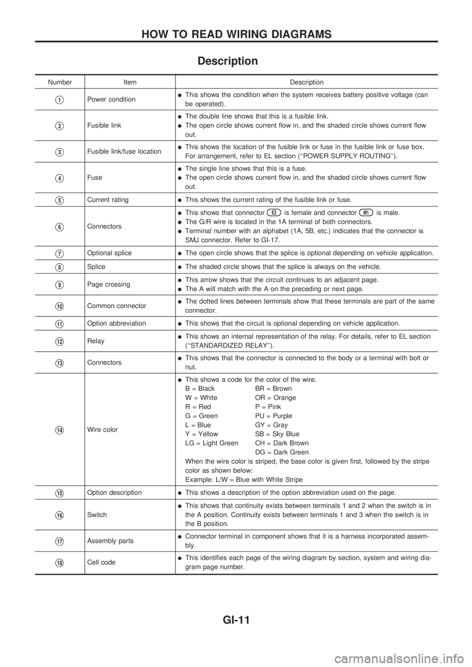
Description
Number Item Description
V1Power conditionlThis shows the condition when the system receives battery positive voltage (can
be operated).
V2Fusible link
lThe double line shows that this is a fusible link.
lThe open circle shows current flow in, and the shaded circle shows current flow
out.
V3Fusible link/fuse locationlThis shows the location of the fusible link or fuse in the fusible link or fuse box.
For arrangement, refer to EL section (``POWER SUPPLY ROUTING'').
V4Fuse
lThe single line shows that this is a fuse.
lThe open circle shows current flow in, and the shaded circle shows current flow
out.
V5Current ratinglThis shows the current rating of the fusible link or fuse.
V6Connectors
lThis shows that connectorE3is female and connectorM1is male.
lThe G/R wire is located in the 1A terminal of both connectors.
lTerminal number with an alphabet (1A, 5B, etc.) indicates that the connector is
SMJ connector. Refer to GI-17.
V7Optional splicelThe open circle shows that the splice is optional depending on vehicle application.
V8SplicelThe shaded circle shows that the splice is always on the vehicle.
V9Page crossinglThis arrow shows that the circuit continues to an adjacent page.
lThe A will match with the A on the preceding or next page.
V10Common connectorlThe dotted lines between terminals show that these terminals are part of the same
connector.
V11Option abbreviationlThis shows that the circuit is optional depending on vehicle application.
V12RelaylThis shows an internal representation of the relay. For details, refer to EL section
(``STANDARDIZED RELAY'').
V13ConnectorslThis shows that the connector is connected to the body or a terminal with bolt or
nut.
V14Wire color
lThis shows a code for the color of the wire.
B = Black BR = Brown
W = White OR = Orange
R = Red P = Pink
G = Green PU = Purple
L = Blue GY = Gray
Y = Yellow SB = Sky Blue
LG = Light Green CH = Dark Brown
DG = Dark Green
When the wire color is striped, the base color is given first, followed by the stripe
color as shown below:
Example: L/W = Blue with White Stripe
V15Option descriptionlThis shows a description of the option abbreviation used on the page.
V16Switch
lThis shows that continuity exists between terminals 1 and 2 when the switch is in
the A position. Continuity exists between terminals 1 and 3 when the switch is in
the B position.
V17Assembly partslConnector terminal in component shows that it is a harness incorporated assem-
bly.
V18Cell codelThis identifies each page of the wiring diagram by section, system and wiring dia-
gram page number.
HOW TO READ WIRING DIAGRAMS
GI-11
Page 835 of 1659
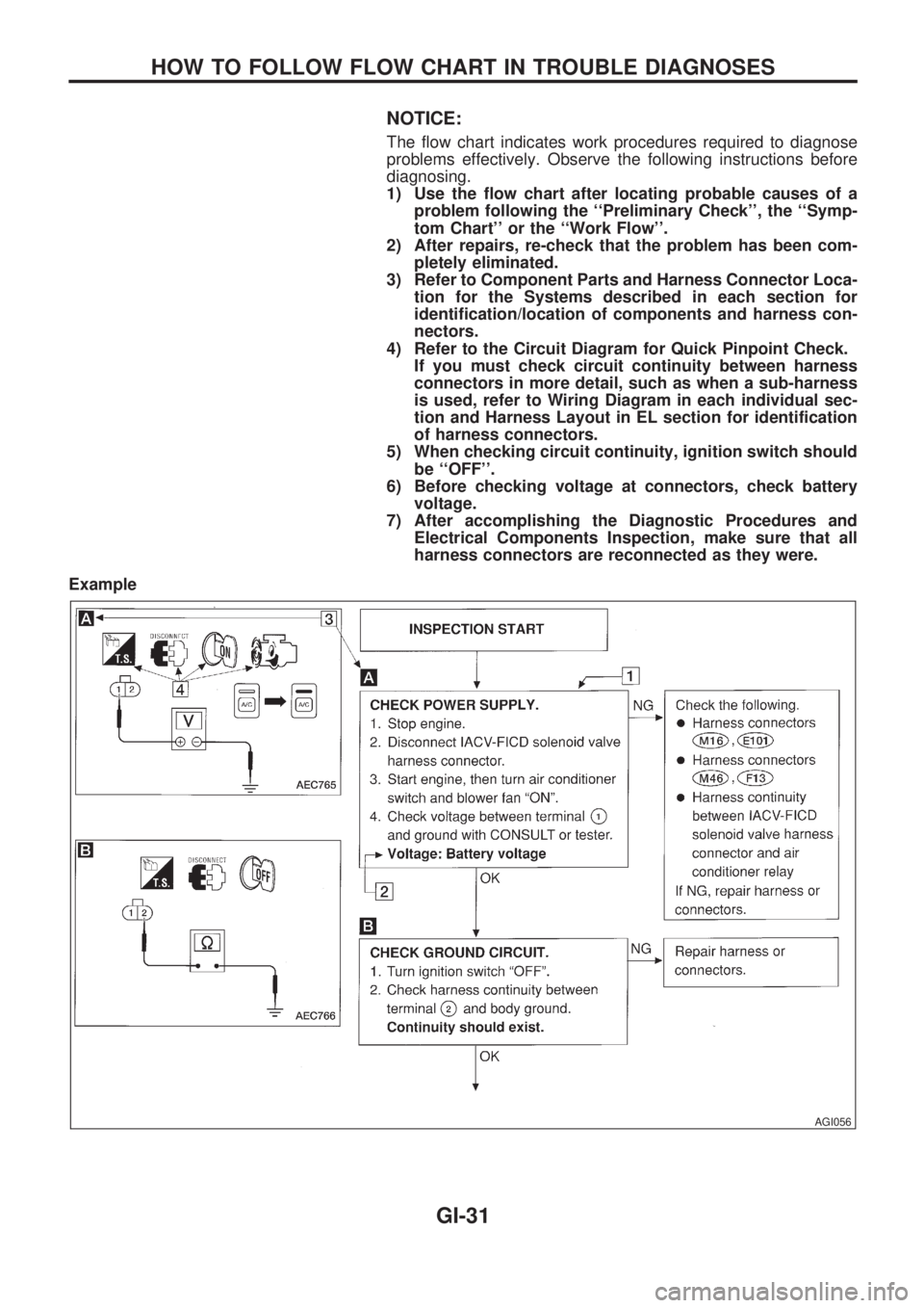
NOTICE:
The flow chart indicates work procedures required to diagnose
problems effectively. Observe the following instructions before
diagnosing.
1) Use the flow chart after locating probable causes of a
problem following the ``Preliminary Check'', the ``Symp-
tom Chart'' or the ``Work Flow''.
2) After repairs, re-check that the problem has been com-
pletely eliminated.
3) Refer to Component Parts and Harness Connector Loca-
tion for the Systems described in each section for
identification/location of components and harness con-
nectors.
4) Refer to the Circuit Diagram for Quick Pinpoint Check.
If you must check circuit continuity between harness
connectors in more detail, such as when a sub-harness
is used, refer to Wiring Diagram in each individual sec-
tion and Harness Layout in EL section for identification
of harness connectors.
5) When checking circuit continuity, ignition switch should
be ``OFF''.
6) Before checking voltage at connectors, check battery
voltage.
7) After accomplishing the Diagnostic Procedures and
Electrical Components Inspection, make sure that all
harness connectors are reconnected as they were.
Example
AGI056
HOW TO FOLLOW FLOW CHART IN TROUBLE DIAGNOSES
GI-31
Page 1446 of 1659
Power Antenna
TROUBLE DIAGNOSES
Symptom Possible causes Repair order
Power antenna does not oper-
ate.1. 7.5A fuse
2. Radio signal
3. Grounds
E6andE39
1. Check 7.5A fuse (No.6, located in fuse block). Verify that
battery positive voltage is present at terminal
V1of power
antenna.
2. Turn ignition switch and radio ON. Verify that battery positive
voltage is present at terminal
V3of power antenna.
3. Check groundsE6andE39.
LOCATION OF ANTENNA
ANTENNA ROD REPLACEMENT
Removal
1. Remove antenna nut and antenna base.
2. Withdraw antenna rod while raising it by operating antenna
motor.
SEL339V
SEL240V
SEL341V
AUDIO ANTENNA
EL-148