towing NISSAN PICK-UP 1998 Repair Manual
[x] Cancel search | Manufacturer: NISSAN, Model Year: 1998, Model line: PICK-UP, Model: NISSAN PICK-UP 1998Pages: 1659, PDF Size: 53.39 MB
Page 804 of 1659
GENERAL INFORMATION
SECTION
GI
CONTENTS
PRECAUTIONS......................................................... 1
Precautions for Supplemental Restraint
System (SRS) ``AIR BAG'' (4WD models)............. 1
Precautions for Supplemental Restraint
System (SRS) ``AIR BAG'' (2WD models)............. 1
Precautions for NATS ............................................ 2
General Precautions .............................................. 2
Precautions for Multiport Fuel Injection System
or ECCS Engine .................................................... 4
Precautions for Three Way Catalyst
(If so equipped) ...................................................... 4
Precautions for Engine Oils ................................... 4
Precautions for Fuel............................................... 5
Precautions for Air Conditioning ............................ 6
HOW TO USE THIS MANUAL.................................. 7
HOW TO READ WIRING DIAGRAMS...................... 9
Sample/Wiring Diagram - EXAMPL - .................... 9
Description ........................................................... 11
HOW TO CHECK TERMINAL................................. 18
How to Probe Connectors ................................... 18
How to Check Enlarged Contact Spring of
Terminal ............................................................... 19
Waterproof Connector Inspection ........................ 20
Terminal Lock Inspection ..................................... 20
HOW TO PERFORM EFFICIENT DIAGNOSIS
FOR AN ELECTRICAL INCIDENT......................... 21
Work Flow ............................................................ 21HOW TO PERFORM EFFICIENT DIAGNOSIS...... 22
Incident Simulation Tests..................................... 22
Circuit Inspection ................................................. 25
HOW TO FOLLOW FLOW CHART IN
TROUBLE DIAGNOSES......................................... 31
How to Follow This Flow Chart ........................... 32
CONSULT CHECKING SYSTEM............................ 34
Function and System Application ........................ 34
Lithium Battery Replacement............................... 34
Checking Equipment ............................................ 35
Loading Procedure............................................... 36
CONSULT Data Link Connector (DLC) Circuit ... 36
IDENTIFICATION INFORMATION.......................... 37
Model Variation .................................................... 37
Identification Number ........................................... 40
Dimensions .......................................................... 44
Wheels and Tires ................................................. 46
LIFTING POINTS AND TOW TRUCK TOWING..... 47
Pantograph Jack .................................................. 47
Screw Jack........................................................... 48
Garage Jack and Safety Stand ........................... 49
2-pole Lift ............................................................. 50
Tow Truck Towing ............................................... 51
Towing Point ........................................................ 53
TIGHTENING TORQUE OF STANDARD BOLTS.. 54
SAE J1930 TERMINOLOGY LIST.......................... 55
SAE J1930 Terminology List ............................... 55
GI
Page 851 of 1659
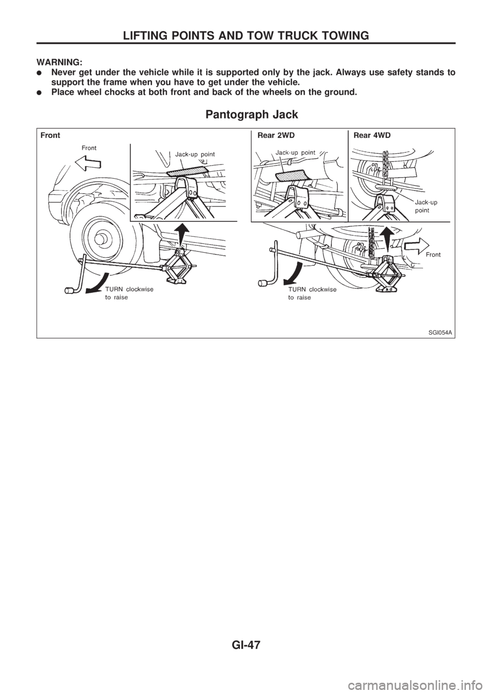
WARNING:
lNever get under the vehicle while it is supported only by the jack. Always use safety stands to
support the frame when you have to get under the vehicle.
lPlace wheel chocks at both front and back of the wheels on the ground.
Pantograph Jack
SGI054A
LIFTING POINTS AND TOW TRUCK TOWING
GI-47
Page 852 of 1659
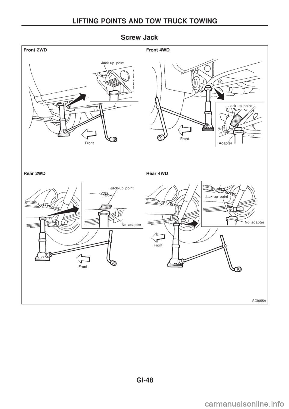
Screw Jack
SGI055A
LIFTING POINTS AND TOW TRUCK TOWING
GI-48
Page 853 of 1659
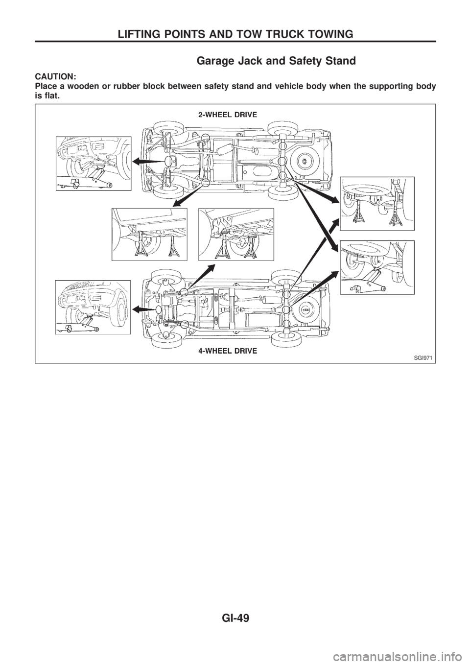
Garage Jack and Safety Stand
CAUTION:
Place a wooden or rubber block between safety stand and vehicle body when the supporting body
is flat.
SGI971
LIFTING POINTS AND TOW TRUCK TOWING
GI-49
Page 854 of 1659
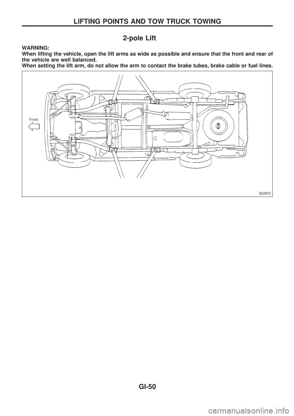
2-pole Lift
WARNING:
When lifting the vehicle, open the lift arms as wide as possible and ensure that the front and rear of
the vehicle are well balanced.
When setting the lift arm, do not allow the arm to contact the brake tubes, brake cable or fuel lines.
SGI972
LIFTING POINTS AND TOW TRUCK TOWING
GI-50
Page 855 of 1659
Tow Truck Towing
CAUTION:
lAll applicable local laws regarding the towing operation must be obeyed.
lIt is necessary to use proper towing equipment to avoid possible damage to the vehicle during
towing operation.
lAttach safety chains for all towing.
lWhen towing, make sure that the transmission, steering system and powertrain are in good order.
If any unit is damaged, a dolly must be used.
lWhen towing with the front wheels on the ground:
Turn the ignition key to the ``OFF'' position and secure the steering wheel in a straight ahead
position with a rope or similar device. Never place the ignition key in the ``LOCK'' position. This
will result in damage to the steering lock mechanism.
lWhen towing with the rear wheels on the ground, release the parking brake and move the gear-
shift lever to neutral position (``N'' position).
lNever tow vehicle from the rear (i.e., backward) with four wheels on the ground as this may cause
serious and expensive damage to the transmission.
lFor 4-wheel drive model:
Set the free-running hubs to the free position. Move the transfer case shift lever into the ``2H''
position and the transmission shift lever into the neutral (``N'') position.
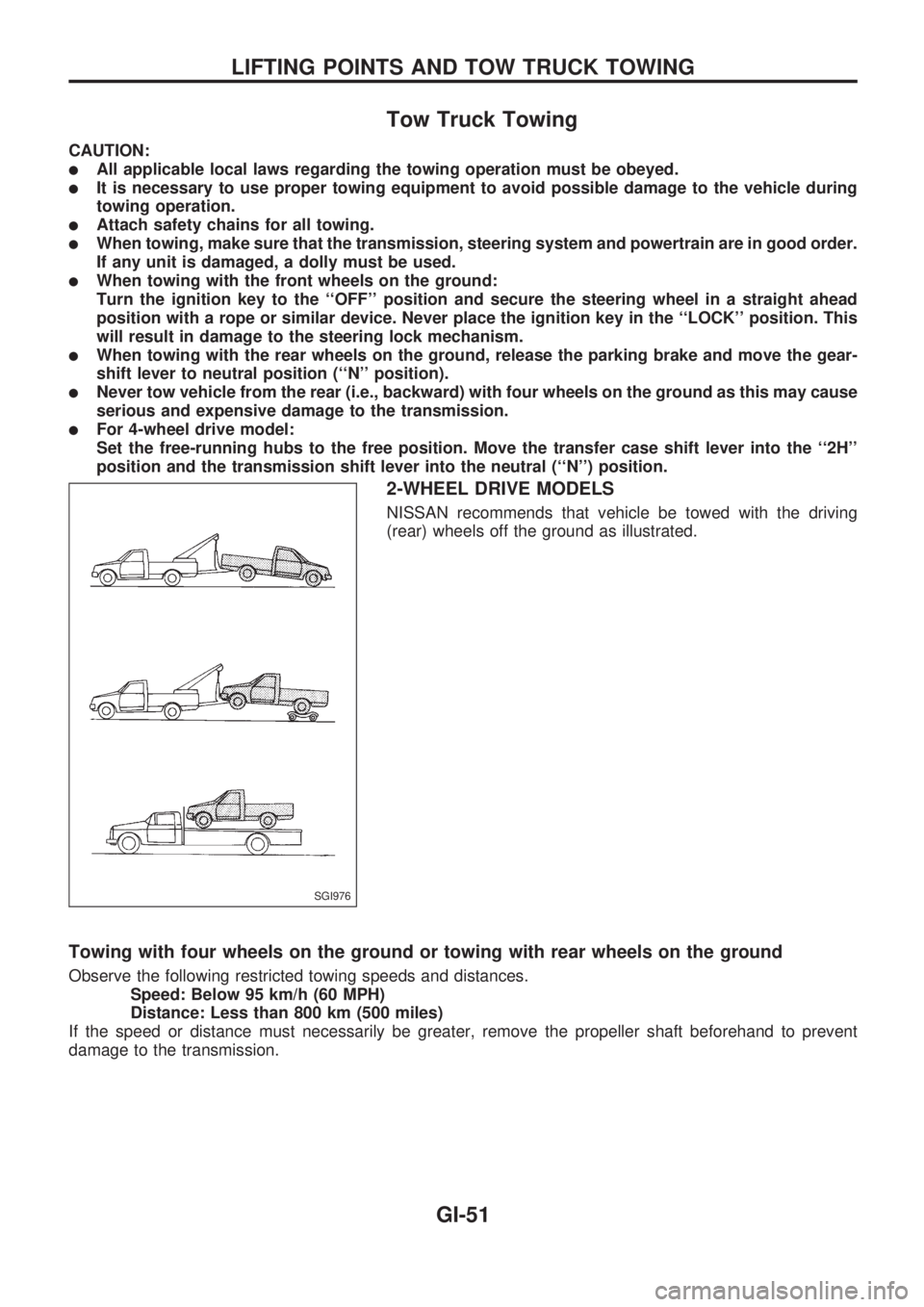
2-WHEEL DRIVE MODELS
NISSAN recommends that vehicle be towed with the driving
(rear) wheels off the ground as illustrated.
Towing with four wheels on the ground or towing with rear wheels on the ground
Observe the following restricted towing speeds and distances.
Speed: Below 95 km/h (60 MPH)
Distance: Less than 800 km (500 miles)
If the speed or distance must necessarily be greater, remove the propeller shaft beforehand to prevent
damage to the transmission.
SGI976
LIFTING POINTS AND TOW TRUCK TOWING
GI-51
Page 856 of 1659
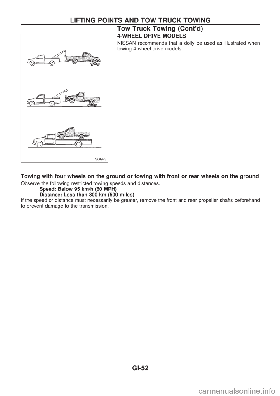
4-WHEEL DRIVE MODELS
NISSAN recommends that a dolly be used as illustrated when
towing 4-wheel drive models.
Towing with four wheels on the ground or towing with front or rear wheels on the ground
Observe the following restricted towing speeds and distances.
Speed: Below 95 km/h (60 MPH)
Distance: Less than 800 km (500 miles)
If the speed or distance must necessarily be greater, remove the front and rear propeller shafts beforehand
to prevent damage to the transmission.
SGI973
LIFTING POINTS AND TOW TRUCK TOWING
Tow Truck Towing (Cont'd)
GI-52
Page 857 of 1659
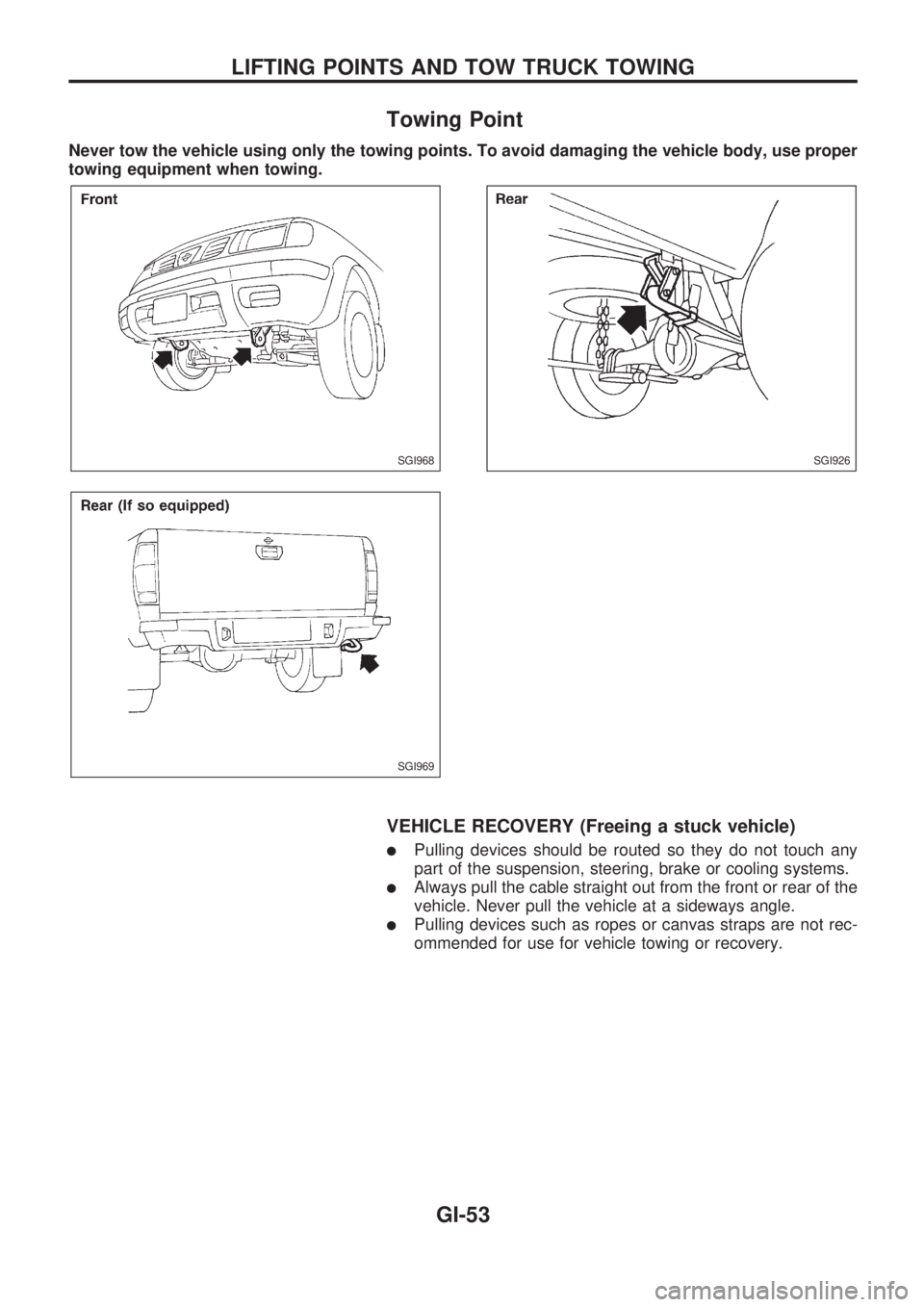
Towing Point
Never tow the vehicle using only the towing points. To avoid damaging the vehicle body, use proper
towing equipment when towing.
VEHICLE RECOVERY (Freeing a stuck vehicle)
lPulling devices should be routed so they do not touch any
part of the suspension, steering, brake or cooling systems.
lAlways pull the cable straight out from the front or rear of the
vehicle. Never pull the vehicle at a sideways angle.
lPulling devices such as ropes or canvas straps are not rec-
ommended for use for vehicle towing or recovery.
SGI968
SGI969
SGI926
LIFTING POINTS AND TOW TRUCK TOWING
GI-53
Page 870 of 1659
Throttle body ................................................. EM-9
Throttle position sensor (TPS)................... EC-113
Throwout bearing - See Clutch release
bearing........................................................ CL-9
Tie-rod .......................................................... ST-37
Tie-rod ball joints.......................................... ST-37
Tightening torque of standard bolts .............. GI-54
Timing chain ................................................ EM-13
Timing gear ................................................. EM-89
Tire rotation ................................................. MA-35
Tire size ........................................................ GI-46
Tooth contact (R180A) ................................ PD-26
Tooth contact (C200) ................................... PD-49
Tooth contact (H233B) ................................ PD-70
Torsion bar spring ........................................ FA-28
Tow truck towing ........................................... GI-51
Towing point.................................................. GI-53
Transfer case ................................................. TF-8
Transfer oil replacement ............................. MA-33
Transfer serial number.................................. GI-43
Transmission case (M/T) (FS5R30A).......... MT-35
Transmission case (M/T) (FS5W71C)......... MT-14
Transmission serial number.......................... GI-43
Tread - FR&RR (Dimensions) ...................... GI-44
Trim .............................................................. BT-15
Triple pressure switch ........................... HA-12, 44
Turn signal lamp........................................... EL-74
Two-pole lift................................................... GI-50
U
Under body ....................................................BT-46
Upper link (front susp.) ................................ FA-31
V
VSS - Wiring diagram .................................EC-119
Vacuum hose (brake system) .......................BR-17
Vacuum hose drawing (ECCS).....................EC-12
Vacuum pump ...............................................BR-19
Valve clearance adjustment .........................MA-23
Valve clearance ............................................EM-31
Valve guide (KA24 engine) ......................... EM-29Valve guide (TD25 engine) ..........................EM-56
Valve lifter .....................................................EM-60
Valve seat (KA24 engine) ............................EM-31
Valve seat (TD25 engine) ............................EM-57
Valve spring (KA24 engine) .........................EM-32
Valve spring (TD25 engine) .........................EM-60
Vehicle identification number .........................GI-40
Vehicle recovery (freeing a stuck
vehicle) .......................................................GI-53
Vehicle speed sensor (VSS).......................EC-118
Ventilator door control rod adjustment .........HA-45
Viscosity number (SAE) ...............................MA-13
W
WARN - Wiring diagram ..............................EL-106
WINDOW - Wiring diagram ........................ EL-157
WIPER - Wiring diagram ............................ EL-122
Warning lamps ........................................... EL-105
Washer, front .............................................. EL-120
Water cock control rod adjustment.............. HA-46
Water pump (KA24 engine) ........................... LC-7
Water pump (TD25 engine) ......................... LC-21
Weatherstrip - See Exterior ......................... BT-24
Wheel alignment (front).................................. FA-7
Wheel balance............................................. MA-34
Wheel bearing (front axle) ............................. FA-5
Wheel bearing (rear)...................................... RA-4
Wheel hub (front) ......................................... FA-16
Wheel sensors (ABS) .................................. BR-35
Wheel size .................................................... GI-46
Wheelbase (Dimensions) .............................. GI-44
Width (Dimensions)....................................... GI-44
Window, back ............................................... BT-24
Window, door ............................................... BT-10
Window, side ................................................ BT-38
Windshield .................................................... BT-36
Wiper, front ................................................. EL-120
Wiring diagram (cell code) list.................... EL-253
Wiring diagrams .............................................. GI-9
Withdrawal lever (clutch)................................ CL-9
Wrist pin - See Piston pin inspection .......... EM-39
ALPHABETICAL INDEX
IDX-8
Page 983 of 1659
Maintenance Under Severe Driving
Conditions
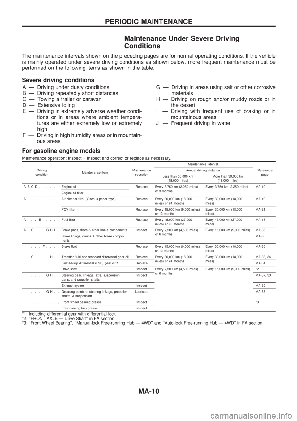
The maintenance intervals shown on the preceding pages are for normal operating conditions. If the vehicle
is mainly operated under severe driving conditions as shown below, more frequent maintenance must be
performed on the following items as shown in the table.
Severe driving conditions
A Ð Driving under dusty conditions
B Ð Driving repeatedly short distances
C Ð Towing a trailer or caravan
D Ð Extensive idling
E Ð Driving in extremely adverse weather condi-
tions or in areas where ambient tempera-
tures are either extremely low or extremely
high
F Ð Driving in high humidity areas or in mountain-
ous areasG Ð Driving in areas using salt or other corrosive
materials
H Ð Driving on rough and/or muddy roads or in
the desert
I Ð Driving with frequent use of braking or in
mountainous areas
J Ð Frequent driving in water
For gasoline engine models
Maintenance operation: Inspect = Inspect and correct or replace as necessary.
Driving
conditionMaintenance itemMaintenance
operationMaintenance interval
Reference
page Annual driving distance
Less than 30,000 km
(18,000 miles)More than 30,000 km
(18,000 miles)
ABCD......Engine oil Replace Every 3,750 km (2,250 miles)
or 3 monthsEvery 3,750 km (2,250 miles) MA-19
Engine oil filter
A.........Aircleaner filter (Viscous paper type) Replace Every 30,000 km (18,000
miles) or 24 monthsEvery 30,000 km (18,000
miles)MA-19
PCV filter Replace Every 15,000 km (9,000 miles)
or 12 monthsEvery 30,000 km (18,000
miles)MA-21
A...E.....Fuel filter Replace Every 45,000 km (27,000
miles) or 36 monthsEvery 45,000 km (27,000
miles)MA-18
A.C...GHI.Brake pads, discs & other brake components Inspect Every 7,500 km (4,500 miles)
or 6 monthsEvery 15,000 km (9,000 miles) MA-36
Brake linings, drums & other brake compo-
nentsMA-36
.....F....Brake fluid Replace Every 15,000 km (9,000 miles)
or 12 monthsEvery 30,000 km (18,000
miles)MA-35
..C....H..Transfer fluid and standard differential gear oil Replace Every 30,000 km (18,000
miles) or 24 monthsEvery 30,000 km (18,000
miles)MA-33, 34
Limited-slip differential (LSD) gear oil*1 ReplaceMA-34
Drive shaft Inspect Every 7,500 km (4,500 miles)
or 6 monthsEvery 15,000 km (9,000 miles) *2
......GH..Steering gear, linkage, axle, suspension
parts, and propeller shaftsInspectMA-37, 33
Exhaust system InspectMA-32
......GH.JGreasing points of steering linkage, propeller
shafts, & suspensionLubricateMA-33
.........JFront wheel bearing grease Inspect*3
Free running hub grease Inspect
*1: Including differential gear with differential lock
*2: ``FRONT AXLE Ð Drive Shaft'' in FA section
*3: ``Front Wheel Bearing'', ``Manual-lock Free-running Hub Ð 4WD'' and ``Auto-lock Free-running Hub Ð 4WD'' in FA section
PERIODIC MAINTENANCE
MA-10