transmission oil NISSAN PICK-UP 1998 Repair Manual
[x] Cancel search | Manufacturer: NISSAN, Model Year: 1998, Model line: PICK-UP, Model: NISSAN PICK-UP 1998Pages: 1659, PDF Size: 53.39 MB
Page 697 of 1659
Removal
Removal order and pointsApplied model
2WD 4WD
1 Remove undercover.jj
2 Drain engine oil.jj
3Remove front propeller shaft
from front differential carrier.Ðj
4Remove front drive shaft fix-
ing bolts (RH & LH).Ðj
5Remove front suspension
crossmember.jj
6Remove differential front
mounting bolts (RH & LH)
and rear mounting bolts.Ðj
7Remove front differential car-
rier.ÐjRemoval order and pointsApplied model
2WD 4WD
8Remove front differential car-
rier mounting bracket.Ðj
9Remove transmission to rear
engine mounting bracket
nuts (RH & LH).jj
10Remove engine mounting
bolts or nuts (RH & LH).jj
11Lift up engine.
If necessary, disconnect
exhaust tube.jj
12 Remove oil pan.jj
WARNING:
lPlace vehicle on a flat and solid surface.
lPlace chocks at front and rear of rear wheels.
lYou should not remove oil pan until exhaust system and
cooling system have completely cooled off.
Otherwise, you may burn yourself and/or fire may break
out in the fuel line.
lWhen removing front and/or rear engine mounting bolts
or nuts, lift up slightly engine for safety work.
CAUTION:
lIn lifting engine, be careful not to hit against adjacent
parts, especially against accelerator wire casing end,
brake tube and brake master cylinder.
lFor tightening torque, refer to EM-71, MT and PD sec-
tions.
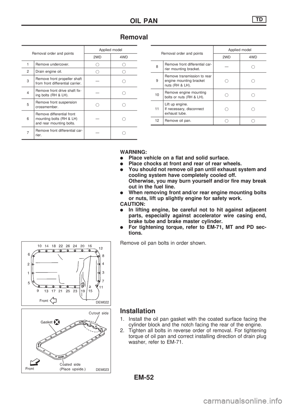
Remove oil pan bolts in order shown.
Installation
1. Install the oil pan gasket with the coated surface facing the
cylinder block and the notch facing the rear of the engine.
2. Tighten all bolts in reverse order of removal. For tightening
torque of oil pan and correct installing direction of drain plug
washer, refer to EM-71.
DEM022
DEM023
OIL PANTD
EM-52
Page 712 of 1659
OIL SEAL INSTALLING DIRECTION
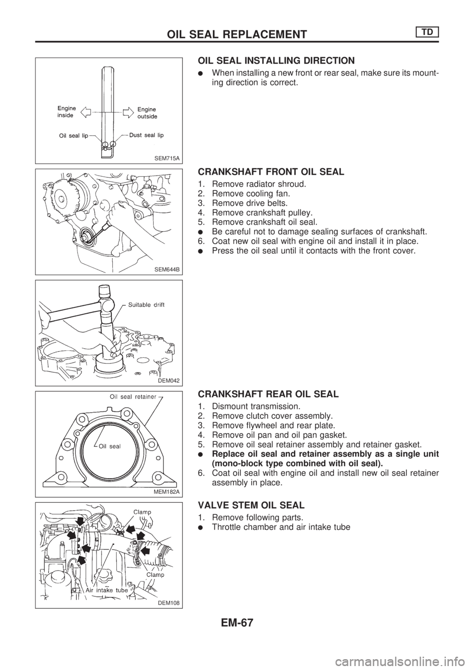
lWhen installing a new front or rear seal, make sure its mount-
ing direction is correct.
CRANKSHAFT FRONT OIL SEAL
1. Remove radiator shroud.
2. Remove cooling fan.
3. Remove drive belts.
4. Remove crankshaft pulley.
5. Remove crankshaft oil seal.
lBe careful not to damage sealing surfaces of crankshaft.
6. Coat new oil seal with engine oil and install it in place.
lPress the oil seal until it contacts with the front cover.
CRANKSHAFT REAR OIL SEAL
1. Dismount transmission.
2. Remove clutch cover assembly.
3. Remove flywheel and rear plate.
4. Remove oil pan and oil pan gasket.
5. Remove oil seal retainer assembly and retainer gasket.
lReplace oil seal and retainer assembly as a single unit
(mono-block type combined with oil seal).
6. Coat oil seal with engine oil and install new oil seal retainer
assembly in place.
VALVE STEM OIL SEAL
1. Remove following parts.
lThrottle chamber and air intake tube
SEM715A
SEM644B
DEM042
MEM182A
DEM108
.
OIL SEAL REPLACEMENTTD
EM-67
Page 715 of 1659
Removal
1. Remove engine undercover and hood.
2. Drain engine coolant.
3. Remove vacuum hoses, fuel tubes, wires, harnesses and
connectors and so on.
4. Remove radiator, shroud and cooling fan.
5. Remove drive belts.
6. Remove power steering oil pump and air conditioner com-
pressor.
7. Remove front exhaust tube.
8. Remove transmission from vehicle.
Refer to MT section.
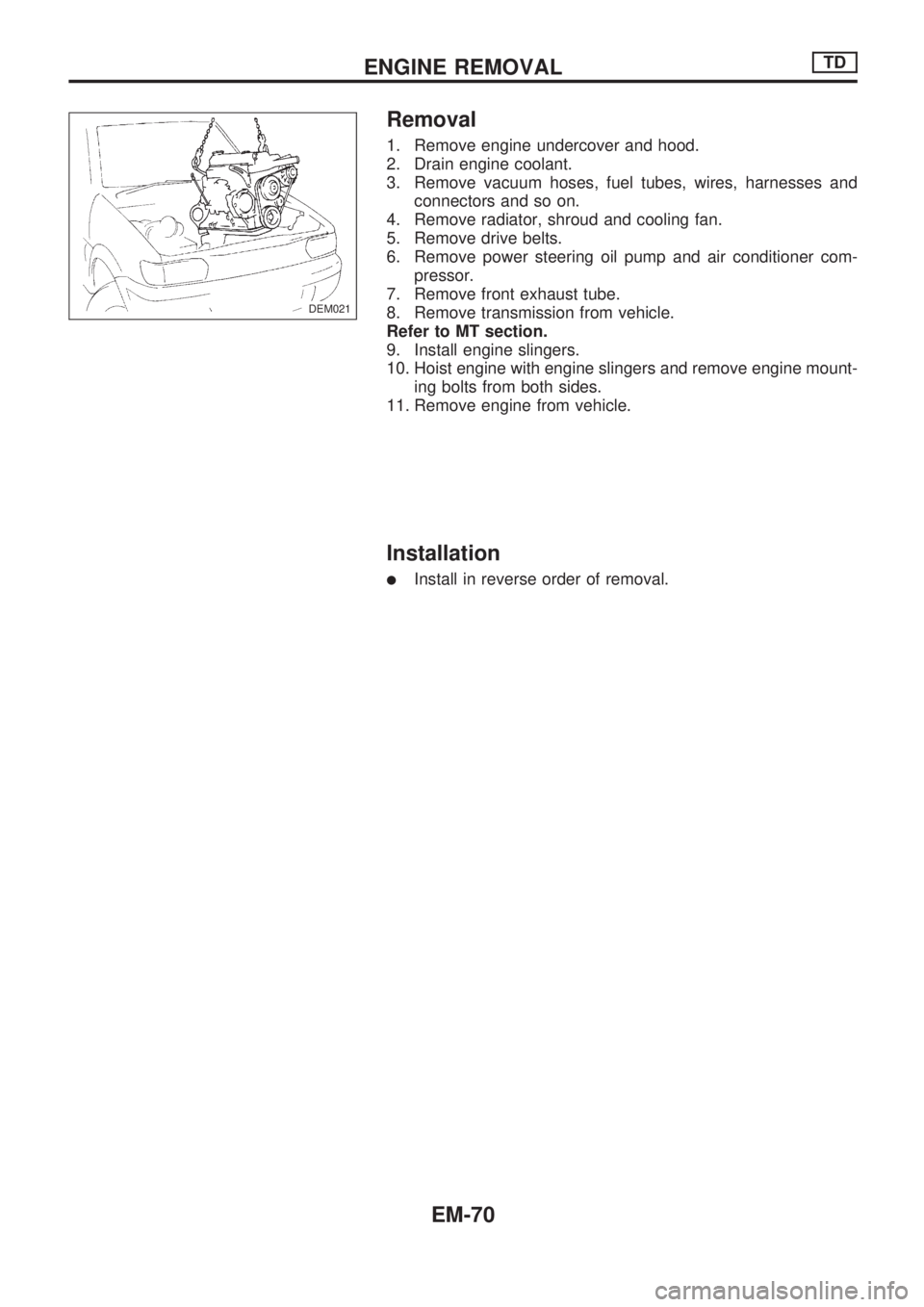
9. Install engine slingers.
10. Hoist engine with engine slingers and remove engine mount-
ing bolts from both sides.
11. Remove engine from vehicle.
Installation
lInstall in reverse order of removal.
DEM021
ENGINE REMOVALTD
EM-70
Page 807 of 1659
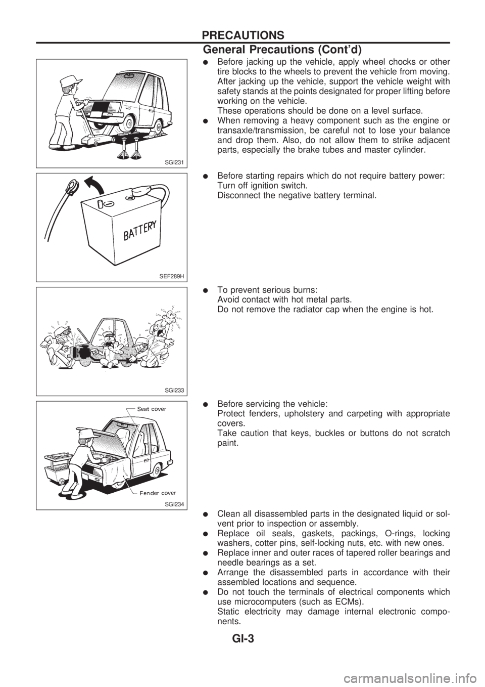
lBefore jacking up the vehicle, apply wheel chocks or other
tire blocks to the wheels to prevent the vehicle from moving.
After jacking up the vehicle, support the vehicle weight with
safety stands at the points designated for proper lifting before
working on the vehicle.
These operations should be done on a level surface.
lWhen removing a heavy component such as the engine or
transaxle/transmission, be careful not to lose your balance
and drop them. Also, do not allow them to strike adjacent
parts, especially the brake tubes and master cylinder.
lBefore starting repairs which do not require battery power:
Turn off ignition switch.
Disconnect the negative battery terminal.
lTo prevent serious burns:
Avoid contact with hot metal parts.
Do not remove the radiator cap when the engine is hot.
lBefore servicing the vehicle:
Protect fenders, upholstery and carpeting with appropriate
covers.
Take caution that keys, buckles or buttons do not scratch
paint.
lClean all disassembled parts in the designated liquid or sol-
vent prior to inspection or assembly.
lReplace oil seals, gaskets, packings, O-rings, locking
washers, cotter pins, self-locking nuts, etc. with new ones.
lReplace inner and outer races of tapered roller bearings and
needle bearings as a set.
lArrange the disassembled parts in accordance with their
assembled locations and sequence.
lDo not touch the terminals of electrical components which
use microcomputers (such as ECMs).
Static electricity may damage internal electronic compo-
nents.
SGI231
SEF289H
SGI233
SGI234
PRECAUTIONS
General Precautions (Cont'd)
GI-3
Page 808 of 1659
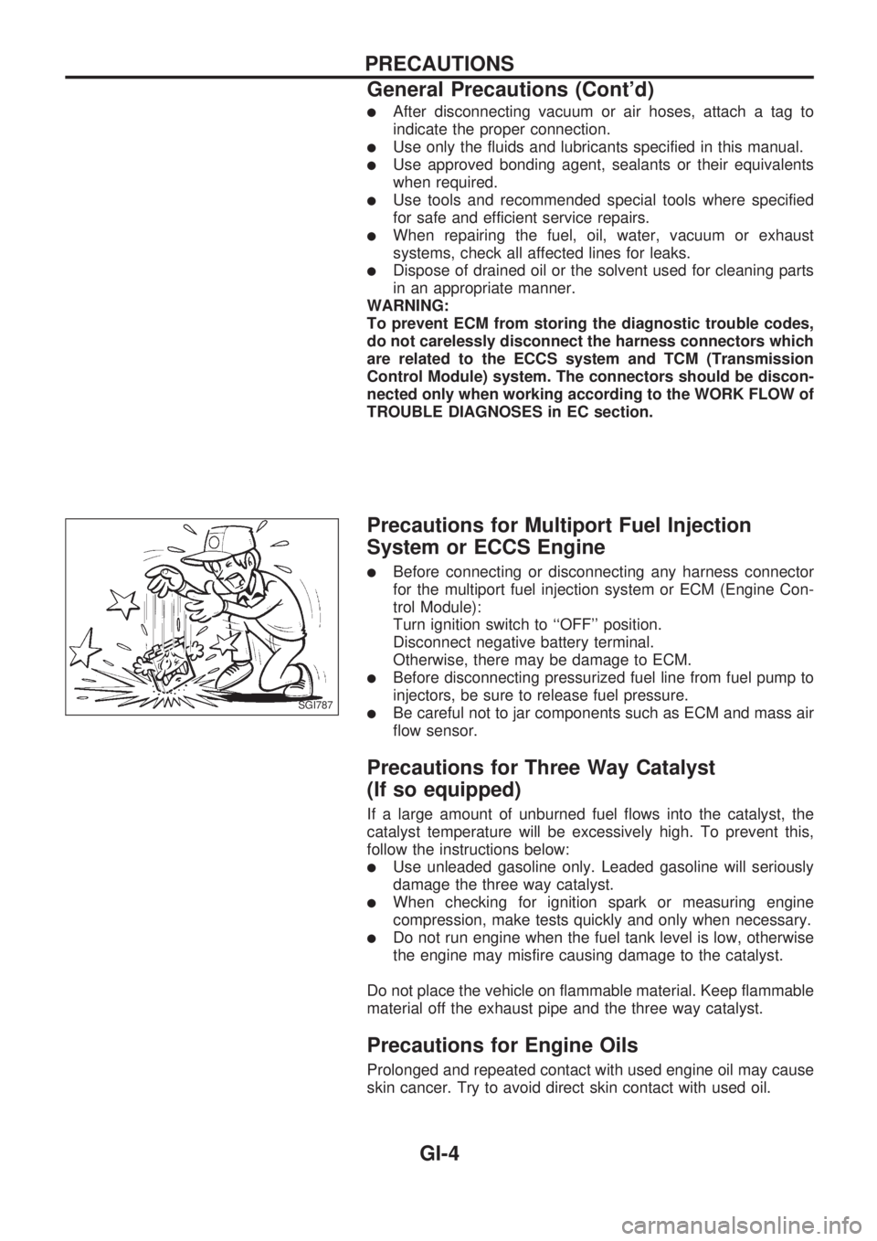
lAfter disconnecting vacuum or air hoses, attach a tag to
indicate the proper connection.
lUse only the fluids and lubricants specified in this manual.
lUse approved bonding agent, sealants or their equivalents
when required.
lUse tools and recommended special tools where specified
for safe and efficient service repairs.
lWhen repairing the fuel, oil, water, vacuum or exhaust
systems, check all affected lines for leaks.
lDispose of drained oil or the solvent used for cleaning parts
in an appropriate manner.
WARNING:
To prevent ECM from storing the diagnostic trouble codes,
do not carelessly disconnect the harness connectors which
are related to the ECCS system and TCM (Transmission
Control Module) system. The connectors should be discon-
nected only when working according to the WORK FLOW of
TROUBLE DIAGNOSES in EC section.
Precautions for Multiport Fuel Injection
System or ECCS Engine
lBefore connecting or disconnecting any harness connector
for the multiport fuel injection system or ECM (Engine Con-
trol Module):
Turn ignition switch to ``OFF'' position.
Disconnect negative battery terminal.
Otherwise, there may be damage to ECM.
lBefore disconnecting pressurized fuel line from fuel pump to
injectors, be sure to release fuel pressure.
lBe careful not to jar components such as ECM and mass air
flow sensor.
Precautions for Three Way Catalyst
(If so equipped)
If a large amount of unburned fuel flows into the catalyst, the
catalyst temperature will be excessively high. To prevent this,
follow the instructions below:
lUse unleaded gasoline only. Leaded gasoline will seriously
damage the three way catalyst.
lWhen checking for ignition spark or measuring engine
compression, make tests quickly and only when necessary.
lDo not run engine when the fuel tank level is low, otherwise
the engine may misfire causing damage to the catalyst.
Do not place the vehicle on flammable material. Keep flammable
material off the exhaust pipe and the three way catalyst.
Precautions for Engine Oils
Prolonged and repeated contact with used engine oil may cause
skin cancer. Try to avoid direct skin contact with used oil.
SGI787
PRECAUTIONS
General Precautions (Cont'd)
GI-4
Page 812 of 1659
lThe followingSYMBOLS AND ABBREVIATIONSare used:
,: Tightening torque
: Should be lubricated with grease.
Unless otherwise indicated, use
recommended multi-purpose
grease.
: Should be lubricated with oil.
: Sealing point
: Checking point
: Always replace after every disas-
sembly.
VP: Apply petroleum jelly.
: Apply ATF.
.: Select with proper thickness.
>: Adjustment is required.
SDS : Service Data and Specifications
LH, RH : Left-Hand, Right-Hand
FR, RR : Front, Rear
M/T : Manual Transaxle/Transmission
A/T : Automatic Transaxle/Transmission
,
4WD : 4-Wheel Drive
2WD : 2-Wheel Drive
A/C : Air Conditioner
P/S : Power Steering
SST : Special Service Tools
SAE : Society of Automotive Engineers,
Inc.
ATF : Automatic Transmission Fluid
D
1: Drive range 1st gear
D
2: Drive range 2nd gear
D
3: Drive range 3rd gear
D
4: Drive range 4th gear
OD : Overdrive
2
2: 2nd range 2nd gear
2
1: 2nd range 1st gear
1
2: 1st range 2nd gear
1
1: 1st range 1st gear
lTheUNITSgiven in this manual are primarily expressed as the SI UNIT (International System of Unit),
and alternatively expressed in the metric system and in the yard/pound system.
``Example''
Tightening torque:
59 - 78 N´m (6.0 - 8.0 kg-m, 43 - 58 ft-lb)
lTROUBLE DIAGNOSESare included in sections dealing with complicated components.
lSERVICE DATA AND SPECIFICATIONSare contained at the end of each section for quick reference
of data.
lThe captionsWARNINGandCAUTIONwarn you of steps that must be followed to prevent personal
injury and/or damage to some part of the vehicle.
WARNINGindicates the possibility of personal injury if instructions are not followed.
CAUTIONindicates the possibility of component damage if instructions are not followed.
BOLD TYPED STATEMENTSexceptWARNINGandCAUTIONgive you helpful information.
HOW TO USE THIS MANUAL
GI-8
Page 868 of 1659
Maintenance (engine) (TD25 engine) ......... MA-23
Major overhaul (Transfer)............................... TF-8
Malfunction indicator lamp (MIL) ................. EC-38
Manifold tightening torque (intake &
exhaust) ................................................... MA-23
Manual-lock free-running hub ...................... FA-14
Manual steering gear ................................... ST-13
Manual transmission number........................ GI-43
Manual transmission oil replacement.......... MA-32
Mass air flow sensor (MAFS) ...................... EC-89
Master cylinder (brake) ................................ BR-12
Master cylinder (clutch) .................................. CL-6
Mirror, door................................................... BT-39
Mode door control linkage adjustment ........ HA-46
Model variation.............................................. GI-37
Molding - See Exterior ................................. BT-24
Multi-remote control system ....................... EL-173
Multiport fuel injection (MFI) system ........... EC-14
N
NATS (Nissan Anti-theft System)
precautions .......................................................GI-2
NATS (Nissan Anti-theft System)............... EL-183
NATS - Wiring diagram .............................. EL-185
Neutral position switch (M/T)....................... MT-14
Neutral position switch............................... EC-136
O
Oil change (capacity)....................................MA-12
Oil change (interval) ...................................... MA-5
Oil cooler (engine)........................................ LC-17
Oil jet ............................................................ LC-18
Oil pan (engine) (KA24 engine) .................. EM-11
Oil pan (engine) (TD25 engine) .................. EM-52
Oil pressure (engine) (KA24 engine) ............. LC-4
Oil pressure (engine) (TD25 engine) ........... LC-13
Oil pressure relief valve (engine)
(KA24 engine) ............................................ LC-5
Oil pressure relief valve (engine)
(TD25 engine) .......................................... LC-16
Oil pump (engine) (KA24 engine) .................. LC-4
Oil pump (engine) (TD25 engine) ................ LC-14
Oil pump regulator valve (engine)
(KA24 engine) ............................................ LC-5
Oil pump regulator valve (engine)
(TD25 engine) .......................................... LC-17
Oil seal replacement (engine)
(KA24 engine).......................................... EM-22
Oil seal replacement (engine)
(TD25 engine).......................................... EM-67
Oil seal replacement (front of final
drive) ........................................................ PD-12
Operating cylinder (clutch) ............................. CL-8
Outside mirror - See Door mirror ................. BT-39
Oversize piston............................................ EM-95
P
P/ANT - Wiring diagram ..............................EL-147
PCV (positive crankcase ventilation) ......... EC-193
PCV filter replacement ................................ MA-21
PCV system inspection ............................... MA-21
PGC/V - Wiring diagram ............................ EC-141
PLA - Wiring diagram ................................ EC-222
PNP/SW - Wiring diagram ......................... EC-137
POWER - Wiring diagram .............................. EL-6
PST/SW - Wiring diagram ......................... EC-157
Pantograph jack ............................................ GI-47
Parking brake control................................... BR-30
Parking lamp ................................................ EL-66
Periodic maintenance .................................... MA-5
Pilot bushing replacement
(KA24 engine).......................................... EM-48
Pilot bushing replacement
(TD25 engine).......................................... EM-79
Piston assembly (KA24 engine) .................. EM-45
Piston assembly (TD25 engine) .................. EM-86
Piston pin inspection (KA24 engine) ........... EM-39
Piston pin inspection (TD25 engine) ........... EM-76
Piston ring inspection (KA24 engine).......... EM-40
Piston ring inspection (TD25 engine).......... EM-76
Piston to bore clearance
(KA24 engine).......................................... EM-41
Piston to bore clearance
(TD25 engine).......................................... EM-75
Power door lock ......................................... EL-166
Power door mirror ...................................... EL-150
Power steering fluid level .................. MA-37, ST-4
Power steering gear (PB48S) ...................... ST-20
Power steering gear (PB59K) ...................... ST-28
Power steering hydraulic system ................... ST-7
Power steering oil pressure switch............ EC-157
Power steering oil pump .............................. ST-34
Power steering system bleeding .................... ST-5
Power supply routing...................................... EL-5
Power transistor & ignition coil .................. EC-105
Power window ............................................ EL-154
Pre-delivery inspection .................................. MA-3
Precautions (General) ..................................... GI-2
Pressure plate - See Clutch cover............... CL-13
Priming pump............................................. EC-192
Propeller shaft................................................ PD-6
Propeller shaft greasing .............................. MA-33
Propeller shaft inspection ............................ MA-33
Propeller shaft vibration ................................. PD-8
Push rod ...................................................... EM-60
Q
Quick-glow system check ...........................EC-203
R
R/FOG - Wiring diagram ...............................EL-72
ALPHABETICAL INDEX
IDX-6
Page 870 of 1659
Throttle body ................................................. EM-9
Throttle position sensor (TPS)................... EC-113
Throwout bearing - See Clutch release
bearing........................................................ CL-9
Tie-rod .......................................................... ST-37
Tie-rod ball joints.......................................... ST-37
Tightening torque of standard bolts .............. GI-54
Timing chain ................................................ EM-13
Timing gear ................................................. EM-89
Tire rotation ................................................. MA-35
Tire size ........................................................ GI-46
Tooth contact (R180A) ................................ PD-26
Tooth contact (C200) ................................... PD-49
Tooth contact (H233B) ................................ PD-70
Torsion bar spring ........................................ FA-28
Tow truck towing ........................................... GI-51
Towing point.................................................. GI-53
Transfer case ................................................. TF-8
Transfer oil replacement ............................. MA-33
Transfer serial number.................................. GI-43
Transmission case (M/T) (FS5R30A).......... MT-35
Transmission case (M/T) (FS5W71C)......... MT-14
Transmission serial number.......................... GI-43
Tread - FR&RR (Dimensions) ...................... GI-44
Trim .............................................................. BT-15
Triple pressure switch ........................... HA-12, 44
Turn signal lamp........................................... EL-74
Two-pole lift................................................... GI-50
U
Under body ....................................................BT-46
Upper link (front susp.) ................................ FA-31
V
VSS - Wiring diagram .................................EC-119
Vacuum hose (brake system) .......................BR-17
Vacuum hose drawing (ECCS).....................EC-12
Vacuum pump ...............................................BR-19
Valve clearance adjustment .........................MA-23
Valve clearance ............................................EM-31
Valve guide (KA24 engine) ......................... EM-29Valve guide (TD25 engine) ..........................EM-56
Valve lifter .....................................................EM-60
Valve seat (KA24 engine) ............................EM-31
Valve seat (TD25 engine) ............................EM-57
Valve spring (KA24 engine) .........................EM-32
Valve spring (TD25 engine) .........................EM-60
Vehicle identification number .........................GI-40
Vehicle recovery (freeing a stuck
vehicle) .......................................................GI-53
Vehicle speed sensor (VSS).......................EC-118
Ventilator door control rod adjustment .........HA-45
Viscosity number (SAE) ...............................MA-13
W
WARN - Wiring diagram ..............................EL-106
WINDOW - Wiring diagram ........................ EL-157
WIPER - Wiring diagram ............................ EL-122
Warning lamps ........................................... EL-105
Washer, front .............................................. EL-120
Water cock control rod adjustment.............. HA-46
Water pump (KA24 engine) ........................... LC-7
Water pump (TD25 engine) ......................... LC-21
Weatherstrip - See Exterior ......................... BT-24
Wheel alignment (front).................................. FA-7
Wheel balance............................................. MA-34
Wheel bearing (front axle) ............................. FA-5
Wheel bearing (rear)...................................... RA-4
Wheel hub (front) ......................................... FA-16
Wheel sensors (ABS) .................................. BR-35
Wheel size .................................................... GI-46
Wheelbase (Dimensions) .............................. GI-44
Width (Dimensions)....................................... GI-44
Window, back ............................................... BT-24
Window, door ............................................... BT-10
Window, side ................................................ BT-38
Windshield .................................................... BT-36
Wiper, front ................................................. EL-120
Wiring diagram (cell code) list.................... EL-253
Wiring diagrams .............................................. GI-9
Withdrawal lever (clutch)................................ CL-9
Wrist pin - See Piston pin inspection .......... EM-39
ALPHABETICAL INDEX
IDX-8
Page 976 of 1659
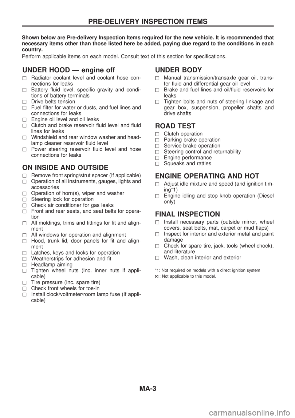
Shown below are Pre-delivery Inspection Items required for the new vehicle. It is recommended that
necessary items other than those listed here be added, paying due regard to the conditions in each
country.
Perform applicable items on each model. Consult text of this section for specifications.
UNDER HOOD Ð engine off
hRadiator coolant level and coolant hose con-
nections for leaks
hBattery fluid level, specific gravity and condi-
tions of battery terminals
hDrive belts tension
hFuel filter for water or dusts, and fuel lines and
connections for leaks
hEngine oil level and oil leaks
hClutch and brake reservoir fluid level and fluid
lines for leaks
hWindshield and rear window washer and head-
lamp cleaner reservoir fluid level
hPower steering reservoir fluid level and hose
connections for leaks
ON INSIDE AND OUTSIDE
hRemove front spring/strut spacer (If applicable)
hOperation of all instruments, gauges, lights and
accessories
hOperation of horn(s), wiper and washer
hSteering lock for operation
hCheck air conditioner for gas leaks
hFront and rear seats, and seat belts for opera-
tion
hAll moldings, trims and fittings for fit and align-
ment
hAll windows for operation and alignment
hHood, trunk lid, door panels for fit and align-
ment
hLatches, keys and locks for operation
hWeatherstrips for adhesion and fit
hHeadlamp aiming
hTighten wheel nuts (Inc. inner nuts if appli-
cable)
hTire pressure (Inc. spare tire)
hCheck front wheels for toe-in
hInstall clock/voltmeter/room lamp fuse (If appli-
cable)
UNDER BODY
hManual transmission/transaxle gear oil, trans-
fer fluid and differential gear oil level
hBrake and fuel lines and oil/fluid reservoirs for
leaks
hTighten bolts and nuts of steering linkage and
gear box, suspension, propeller shafts and
drive shafts
ROAD TEST
hClutch operation
hParking brake operation
hService brake operation
hSteering control and returnability
hEngine performance
hSqueaks and rattles
ENGINE OPERATING AND HOT
hAdjust idle mixture and speed (and ignition tim-
ing*1)
hEngine idling and stop knob operation (Diesel
only)
FINAL INSPECTION
hInstall necessary parts (outside mirror, wheel
covers, seat belts, mat, carpet or mud flaps)
hInspect for interior and exterior metal and paint
damage
hCheck for spare tire, jack, tools (wheel chock),
and literature
hWash, clean interior and exterior
*1: Not required on models with a direct ignition system
h
X: Not applicable to this model.
PRE-DELIVERY INSPECTION ITEMS
MA-3
Page 979 of 1659
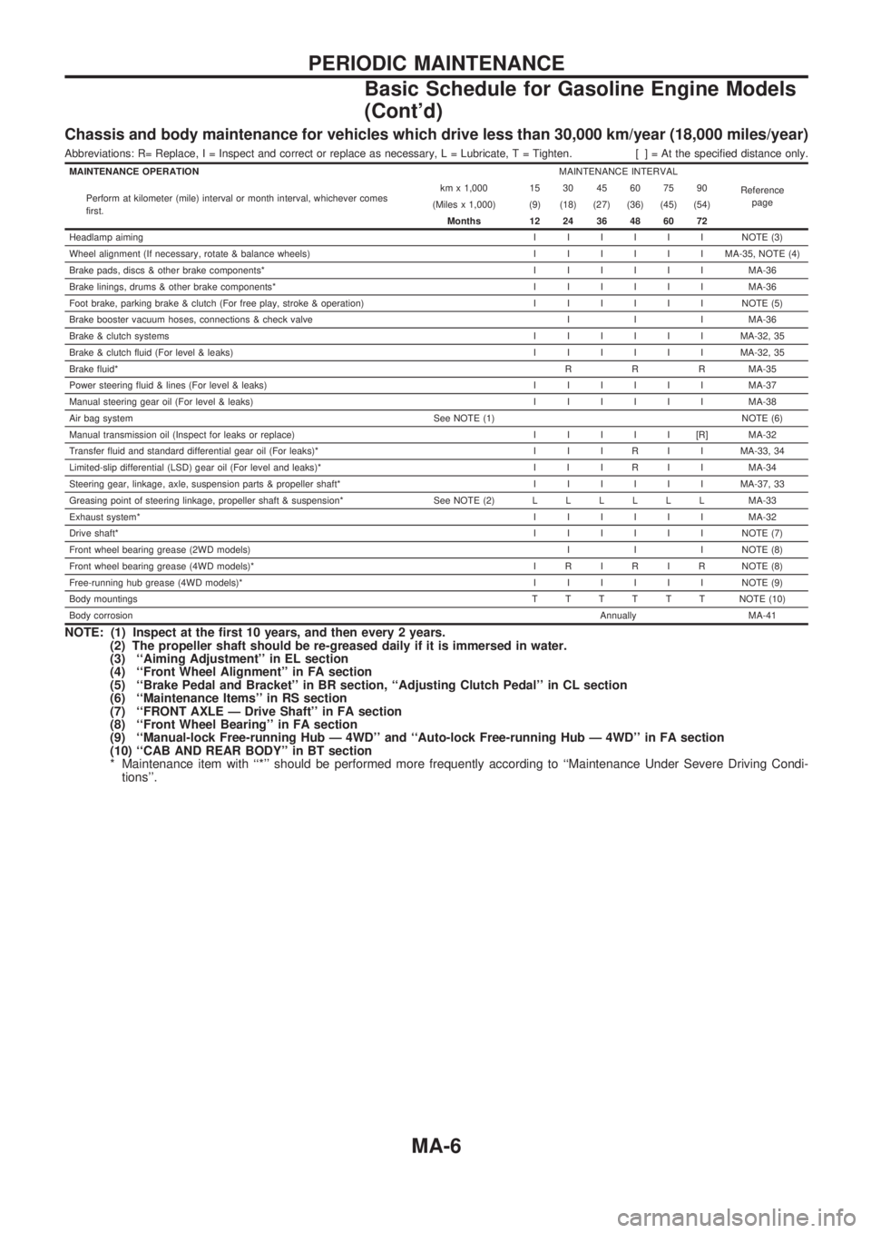
Chassis and body maintenance for vehicles which drive less than 30,000 km/year (18,000 miles/year)
Abbreviations: R= Replace, I = Inspect and correct or replace as necessary, L = Lubricate, T = Tighten. [ ] = At the specified distance only.
MAINTENANCE OPERATIONMAINTENANCE INTERVAL
Reference
page Perform at kilometer (mile) interval or month interval, whichever comes
first.km x 1,000 15 30 45 60 75 90
(Miles x 1,000) (9) (18) (27) (36) (45) (54)
Months 12 24 36 48 60 72
Headlamp aimingIIIIIINOTE (3)
Wheel alignment (If necessary, rotate & balance wheels)IIIIIIMA-35, NOTE (4)
Brake pads, discs & other brake components*IIIIIIMA-36
Brake linings, drums & other brake components*IIIIIIMA-36
Foot brake, parking brake & clutch (For free play, stroke & operation)IIIIIINOTE (5)
Brake booster vacuum hoses, connections & check valve I I I MA-36
Brake & clutch systemsIIIIIIMA-32, 35
Brake & clutch fluid (For level & leaks)IIIIIIMA-32, 35
Brake fluid*R R R MA-35
Power steering fluid & lines (For level & leaks)IIIIIIMA-37
Manual steering gear oil (For level & leaks)IIIIIIMA-38
Air bag system See NOTE (1) NOTE (6)
Manual transmission oil (Inspect for leaks or replace)IIIII[R]MA-32
Transfer fluid and standard differential gear oil (For leaks)* I I I R I I MA-33, 34
Limited-slip differential (LSD) gear oil (For level and leaks)* I I I R I I MA-34
Steering gear, linkage, axle, suspension parts & propeller shaft*IIIIIIMA-37, 33
Greasing point of steering linkage, propeller shaft & suspension* See NOTE (2)LLLLLLMA-33
Exhaust system*IIIIIIMA-32
Drive shaft*IIIIIINOTE (7)
Front wheel bearing grease (2WD models)I I I NOTE (8)
Front wheel bearing grease (4WD models)* I R I R I R NOTE (8)
Free-running hub grease (4WD models)*IIIIIINOTE (9)
Body mountingsTTTTTTNOTE (10)
Body corrosionAnnually MA-41
NOTE: (1) Inspect at the first 10 years, and then every 2 years.
(2) The propeller shaft should be re-greased daily if it is immersed in water.
(3) ``Aiming Adjustment'' in EL section
(4) ``Front Wheel Alignment'' in FA section
(5) ``Brake Pedal and Bracket'' in BR section, ``Adjusting Clutch Pedal'' in CL section
(6) ``Maintenance Items'' in RS section
(7) ``FRONT AXLE Ð Drive Shaft'' in FA section
(8) ``Front Wheel Bearing'' in FA section
(9) ``Manual-lock Free-running Hub Ð 4WD'' and ``Auto-lock Free-running Hub Ð 4WD'' in FA section
(10) ``CAB AND REAR BODY'' in BT section
* Maintenance item with ``*'' should be performed more frequently according to ``Maintenance Under Severe Driving Condi-
tions''.
PERIODIC MAINTENANCE
Basic Schedule for Gasoline Engine Models
(Cont'd)
MA-6