air conditioning NISSAN PICK-UP 2001 Repair Manual
[x] Cancel search | Manufacturer: NISSAN, Model Year: 2001, Model line: PICK-UP, Model: NISSAN PICK-UP 2001Pages: 1306, PDF Size: 31.7 MB
Page 26 of 1306
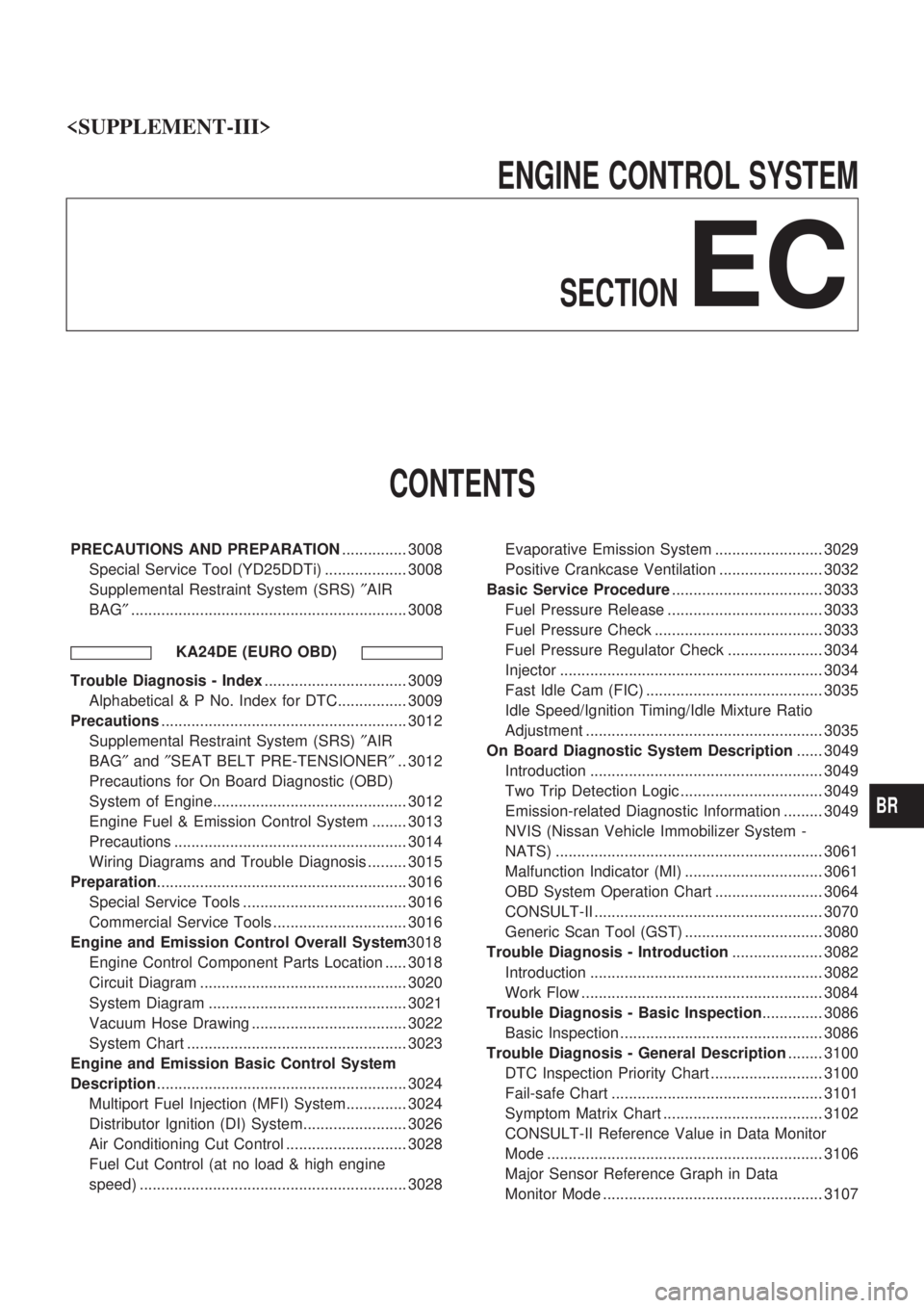
ENGINE CONTROL SYSTEM
SECTION
EC
CONTENTS
PRECAUTIONS AND PREPARATION............... 3008
Special Service Tool (YD25DDTi) ................... 3008
Supplemental Restraint System (SRS)²AIR
BAG²................................................................ 3008
KA24DE (EURO OBD)
Trouble Diagnosis - Index................................. 3009
Alphabetical & P No. Index for DTC................ 3009
Precautions......................................................... 3012
Supplemental Restraint System (SRS)²AIR
BAG²and²SEAT BELT PRE-TENSIONER².. 3012
Precautions for On Board Diagnostic (OBD)
System of Engine............................................. 3012
Engine Fuel & Emission Control System ........ 3013
Precautions ...................................................... 3014
Wiring Diagrams and Trouble Diagnosis ......... 3015
Preparation.......................................................... 3016
Special Service Tools ...................................... 3016
Commercial Service Tools ............................... 3016
Engine and Emission Control Overall System3018
Engine Control Component Parts Location ..... 3018
Circuit Diagram ................................................ 3020
System Diagram .............................................. 3021
Vacuum Hose Drawing .................................... 3022
System Chart ................................................... 3023
Engine and Emission Basic Control System
Description.......................................................... 3024
Multiport Fuel Injection (MFI) System.............. 3024
Distributor Ignition (DI) System........................ 3026
Air Conditioning Cut Control ............................ 3028
Fuel Cut Control (at no load & high engine
speed) .............................................................. 3028Evaporative Emission System ......................... 3029
Positive Crankcase Ventilation ........................ 3032
Basic Service Procedure................................... 3033
Fuel Pressure Release .................................... 3033
Fuel Pressure Check ....................................... 3033
Fuel Pressure Regulator Check ...................... 3034
Injector ............................................................. 3034
Fast Idle Cam (FIC) ......................................... 3035
Idle Speed/Ignition Timing/Idle Mixture Ratio
Adjustment ....................................................... 3035
On Board Diagnostic System Description...... 3049
Introduction ...................................................... 3049
Two Trip Detection Logic ................................. 3049
Emission-related Diagnostic Information ......... 3049
NVIS (Nissan Vehicle Immobilizer System -
NATS) .............................................................. 3061
Malfunction Indicator (MI) ................................ 3061
OBD System Operation Chart ......................... 3064
CONSULT-II ..................................................... 3070
Generic Scan Tool (GST) ................................ 3080
Trouble Diagnosis - Introduction..................... 3082
Introduction ...................................................... 3082
Work Flow ........................................................ 3084
Trouble Diagnosis - Basic Inspection.............. 3086
Basic Inspection ............................................... 3086
Trouble Diagnosis - General Description........ 3100
DTC Inspection Priority Chart .......................... 3100
Fail-safe Chart ................................................. 3101
Symptom Matrix Chart ..................................... 3102
CONSULT-II Reference Value in Data Monitor
Mode ................................................................ 3106
Major Sensor Reference Graph in Data
Monitor Mode ................................................... 3107
BR
Page 30 of 1306
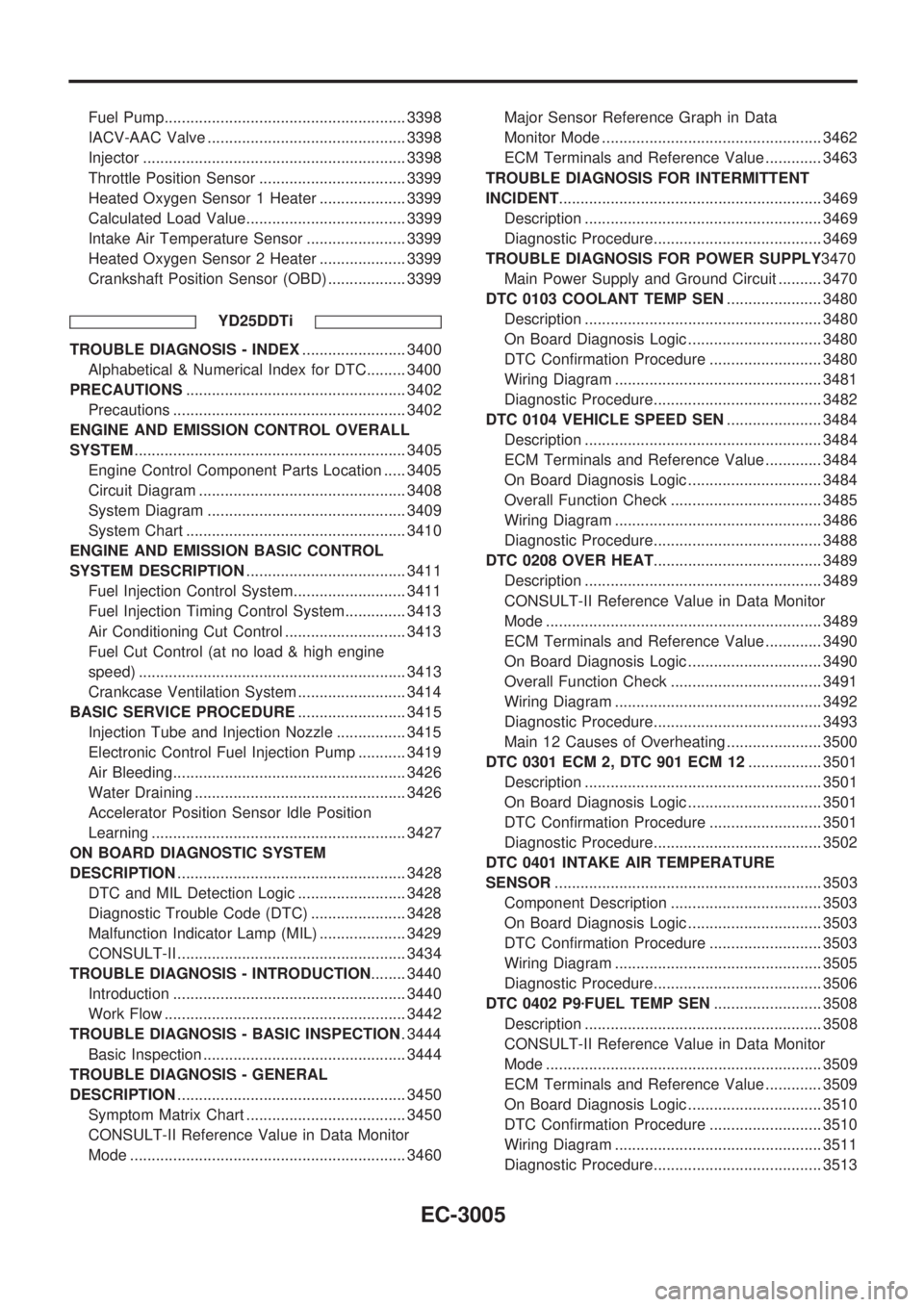
Fuel Pump........................................................ 3398
IACV-AAC Valve .............................................. 3398
Injector ............................................................. 3398
Throttle Position Sensor .................................. 3399
Heated Oxygen Sensor 1 Heater .................... 3399
Calculated Load Value..................................... 3399
Intake Air Temperature Sensor ....................... 3399
Heated Oxygen Sensor 2 Heater .................... 3399
Crankshaft Position Sensor (OBD) .................. 3399
YD25DDTi
TROUBLE DIAGNOSIS - INDEX........................ 3400
Alphabetical & Numerical Index for DTC......... 3400
PRECAUTIONS................................................... 3402
Precautions ...................................................... 3402
ENGINE AND EMISSION CONTROL OVERALL
SYSTEM............................................................... 3405
Engine Control Component Parts Location ..... 3405
Circuit Diagram ................................................ 3408
System Diagram .............................................. 3409
System Chart ................................................... 3410
ENGINE AND EMISSION BASIC CONTROL
SYSTEM DESCRIPTION..................................... 3411
Fuel Injection Control System.......................... 3411
Fuel Injection Timing Control System.............. 3413
Air Conditioning Cut Control ............................ 3413
Fuel Cut Control (at no load & high engine
speed) .............................................................. 3413
Crankcase Ventilation System ......................... 3414
BASIC SERVICE PROCEDURE......................... 3415
Injection Tube and Injection Nozzle ................ 3415
Electronic Control Fuel Injection Pump ........... 3419
Air Bleeding...................................................... 3426
Water Draining ................................................. 3426
Accelerator Position Sensor Idle Position
Learning ........................................................... 3427
ON BOARD DIAGNOSTIC SYSTEM
DESCRIPTION..................................................... 3428
DTC and MIL Detection Logic ......................... 3428
Diagnostic Trouble Code (DTC) ...................... 3428
Malfunction Indicator Lamp (MIL) .................... 3429
CONSULT-II ..................................................... 3434
TROUBLE DIAGNOSIS - INTRODUCTION........ 3440
Introduction ...................................................... 3440
Work Flow ........................................................ 3442
TROUBLE DIAGNOSIS - BASIC INSPECTION. 3444
Basic Inspection ............................................... 3444
TROUBLE DIAGNOSIS - GENERAL
DESCRIPTION..................................................... 3450
Symptom Matrix Chart ..................................... 3450
CONSULT-II Reference Value in Data Monitor
Mode ................................................................ 3460Major Sensor Reference Graph in Data
Monitor Mode ................................................... 3462
ECM Terminals and Reference Value ............. 3463
TROUBLE DIAGNOSIS FOR INTERMITTENT
INCIDENT............................................................. 3469
Description ....................................................... 3469
Diagnostic Procedure....................................... 3469
TROUBLE DIAGNOSIS FOR POWER SUPPLY3470
Main Power Supply and Ground Circuit .......... 3470
DTC 0103 COOLANT TEMP SEN...................... 3480
Description ....................................................... 3480
On Board Diagnosis Logic ............................... 3480
DTC Confirmation Procedure .......................... 3480
Wiring Diagram ................................................ 3481
Diagnostic Procedure....................................... 3482
DTC 0104 VEHICLE SPEED SEN...................... 3484
Description ....................................................... 3484
ECM Terminals and Reference Value ............. 3484
On Board Diagnosis Logic ............................... 3484
Overall Function Check ................................... 3485
Wiring Diagram ................................................ 3486
Diagnostic Procedure....................................... 3488
DTC 0208 OVER HEAT....................................... 3489
Description ....................................................... 3489
CONSULT-II Reference Value in Data Monitor
Mode ................................................................ 3489
ECM Terminals and Reference Value ............. 3490
On Board Diagnosis Logic ............................... 3490
Overall Function Check ................................... 3491
Wiring Diagram ................................................ 3492
Diagnostic Procedure....................................... 3493
Main 12 Causes of Overheating ...................... 3500
DTC 0301 ECM 2, DTC 901 ECM 12................. 3501
Description ....................................................... 3501
On Board Diagnosis Logic ............................... 3501
DTC Confirmation Procedure .......................... 3501
Diagnostic Procedure....................................... 3502
DTC 0401 INTAKE AIR TEMPERATURE
SENSOR.............................................................. 3503
Component Description ................................... 3503
On Board Diagnosis Logic ............................... 3503
DTC Confirmation Procedure .......................... 3503
Wiring Diagram ................................................ 3505
Diagnostic Procedure....................................... 3506
DTC 0402 P9zFUEL TEMP SEN......................... 3508
Description ....................................................... 3508
CONSULT-II Reference Value in Data Monitor
Mode ................................................................ 3509
ECM Terminals and Reference Value ............. 3509
On Board Diagnosis Logic ............................... 3510
DTC Confirmation Procedure .......................... 3510
Wiring Diagram ................................................ 3511
Diagnostic Procedure....................................... 3513
EC-3005
Page 48 of 1306
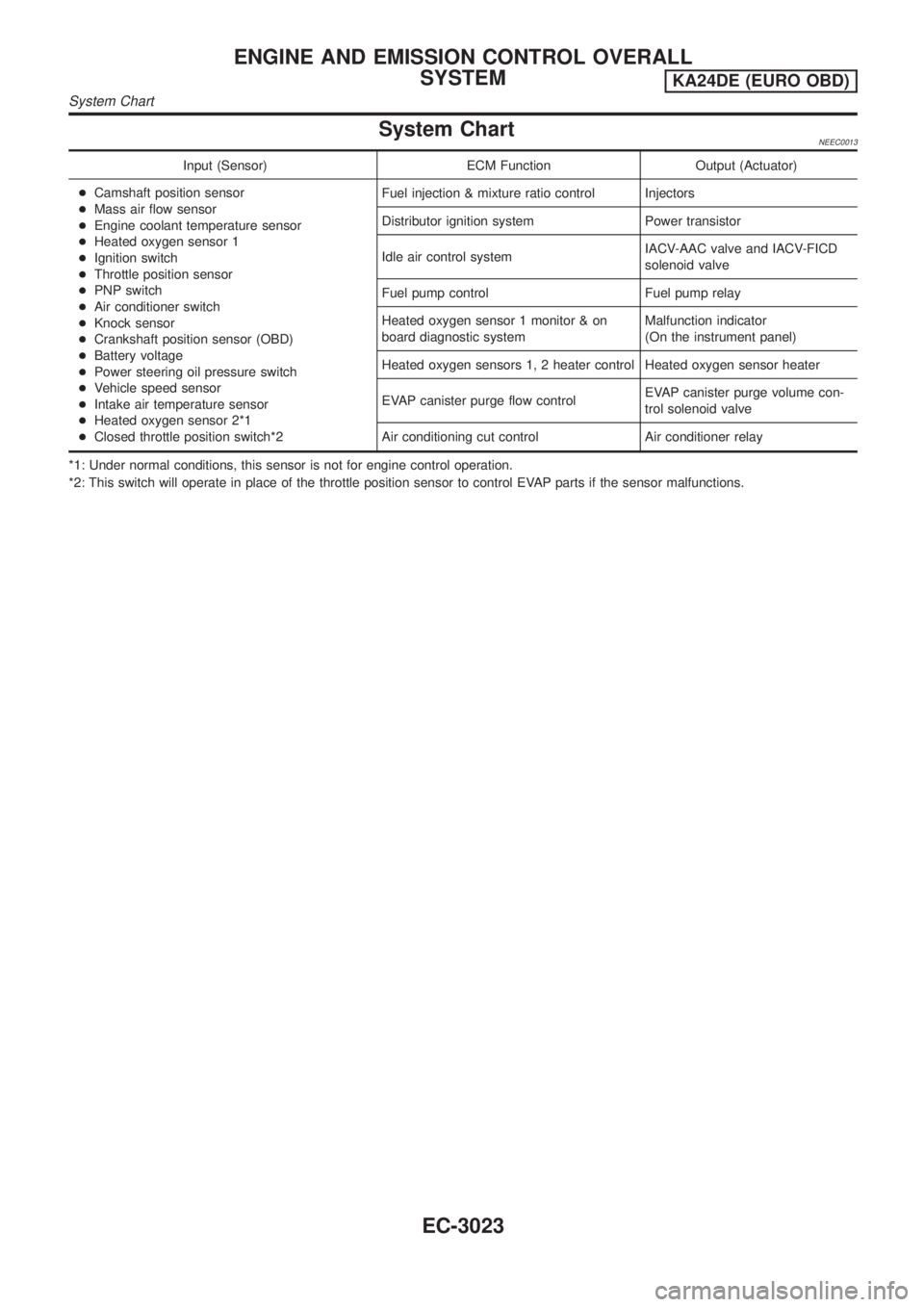
System ChartNEEC0013
Input (Sensor) ECM Function Output (Actuator)
+Camshaft position sensor
+Mass air flow sensor
+Engine coolant temperature sensor
+Heated oxygen sensor 1
+Ignition switch
+Throttle position sensor
+PNP switch
+Air conditioner switch
+Knock sensor
+Crankshaft position sensor (OBD)
+Battery voltage
+Power steering oil pressure switch
+Vehicle speed sensor
+Intake air temperature sensor
+Heated oxygen sensor 2*1
+Closed throttle position switch*2Fuel injection & mixture ratio control Injectors
Distributor ignition system Power transistor
Idle air control systemIACV-AAC valve and IACV-FICD
solenoid valve
Fuel pump control Fuel pump relay
Heated oxygen sensor 1 monitor & on
board diagnostic systemMalfunction indicator
(On the instrument panel)
Heated oxygen sensors 1, 2 heater control Heated oxygen sensor heater
EVAP canister purge flow controlEVAP canister purge volume con-
trol solenoid valve
Air conditioning cut control Air conditioner relay
*1: Under normal conditions, this sensor is not for engine control operation.
*2: This switch will operate in place of the throttle position sensor to control EVAP parts if the sensor malfunctions.
ENGINE AND EMISSION CONTROL OVERALL
SYSTEM
KA24DE (EURO OBD)
System Chart
EC-3023
Page 53 of 1306
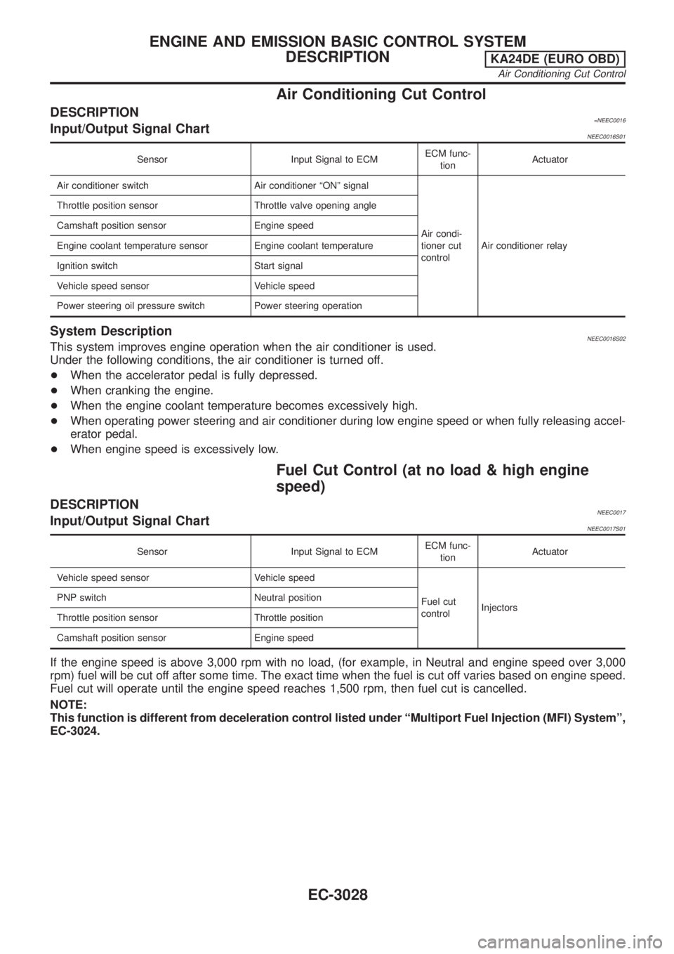
Air Conditioning Cut Control
DESCRIPTION=NEEC0016Input/Output Signal ChartNEEC0016S01
Sensor Input Signal to ECMECM func-
tionActuator
Air conditioner switch Air conditioner ªONº signal
Air condi-
tioner cut
controlAir conditioner relay Throttle position sensor Throttle valve opening angle
Camshaft position sensor Engine speed
Engine coolant temperature sensor Engine coolant temperature
Ignition switch Start signal
Vehicle speed sensor Vehicle speed
Power steering oil pressure switch Power steering operation
System DescriptionNEEC0016S02This system improves engine operation when the air conditioner is used.
Under the following conditions, the air conditioner is turned off.
+When the accelerator pedal is fully depressed.
+When cranking the engine.
+When the engine coolant temperature becomes excessively high.
+When operating power steering and air conditioner during low engine speed or when fully releasing accel-
erator pedal.
+When engine speed is excessively low.
Fuel Cut Control (at no load & high engine
speed)
DESCRIPTIONNEEC0017Input/Output Signal ChartNEEC0017S01
Sensor Input Signal to ECMECM func-
tionActuator
Vehicle speed sensor Vehicle speed
Fuel cut
controlInjectors PNP switch Neutral position
Throttle position sensor Throttle position
Camshaft position sensor Engine speed
If the engine speed is above 3,000 rpm with no load, (for example, in Neutral and engine speed over 3,000
rpm) fuel will be cut off after some time. The exact time when the fuel is cut off varies based on engine speed.
Fuel cut will operate until the engine speed reaches 1,500 rpm, then fuel cut is cancelled.
NOTE:
This function is different from deceleration control listed under ªMultiport Fuel Injection (MFI) Systemº,
EC-3024.
ENGINE AND EMISSION BASIC CONTROL SYSTEM
DESCRIPTION
KA24DE (EURO OBD)
Air Conditioning Cut Control
EC-3028
Page 100 of 1306
![NISSAN PICK-UP 2001 Repair Manual Monitored item [Unit]ECM
input
signalsMain
signalsDescription Remarks
THRTL POS SEN [V]jj+The throttle position sensor signal volt-
age is displayed.
INT/A TEMP SE
[ÉC] or [ÉF]jj+The intake air temp](/img/5/57372/w960_57372-99.png "NISSAN PICK-UP 2001 Repair Manual Monitored item [Unit]ECM
input
signalsMain
signalsDescription Remarks
THRTL POS SEN [V]jj+The throttle position sensor signal volt-
age is displayed.
INT/A TEMP SE
[ÉC] or [ÉF]jj+The intake air temp")
Monitored item [Unit]ECM
input
signalsMain
signalsDescription Remarks
THRTL POS SEN [V]jj+The throttle position sensor signal volt-
age is displayed.
INT/A TEMP SE
[ÉC] or [ÉF]jj+The intake air temperature determined
by the signal voltage of the intake air
temperature sensor is indicated.
START SIGNAL
[ON/OFF]jj+Indicates [ON/OFF] condition from the
starter signal.+After starting the engine, [OFF] is dis-
played regardless of the starter sig-
nal.
CLSD THL POS
[ON/OFF]jj+Indicates idle position [ON/OFF] com-
puted by ECM according to the throttle
position sensor signal.
CLSD THL/P SW
[ON/OFF]j+Indicates mechanical contact [ON/OFF]
condition of the closed throttle position
switch.
AIR COND SIG
[ON/OFF]jj+Indicates [ON/OFF] condition of the air
conditioner switch as determined by
the air conditioning signal.
P/N POSI SW
[ON/OFF]jj+Indicates [ON/OFF] condition from the
PNP switch signal.
PW/ST SIGNAL
[ON/OFF]jj+Indicates [ON/OFF] condition of the
power steering oil pressure switch
determined by the power steering oil
pressure switch signal.
AMB TEMP SW
[ON/OFF]j+Indicates [ON/OFF] condition from the
ambient air temperature switch signal.
IGNITION SW
[ON/OFF]j+Indicates [ON/OFF] condition from igni-
tion switch.
INJ PULSE-B1 [msec]j+Indicates the actual fuel injection pulse
width compensated by ECM according
to the input signals.+When the engine is stopped, a cer-
tain computed value is indicated.
IGN TIMING [BTDC]j+Indicates the ignition timing computed
by ECM according to the input signals.
CAL/LD VALUE [%]+ªCalculated load valueº indicates the
value of the current airflow divided by
peak airflow.
ABSOL TH´P/S [%]+ªAbsolute throttle position sensorº indi-
cates the throttle opening computed by
ECM according to the signal voltage of
the throttle position sensor.
MASS AIRFLOW
[g´m/s]+Indicates the mass airflow computed by
ECM according to the signal voltage of
the mass air flow sensor.
IACV-AAC/V [%]j+Indicates the IACV-AAC valve control
value computed by ECM according to
the input signals.
PURG VOL C/V [%]+Indicates the EVAP canister purge vol-
ume control value computed by the
ECM according to the input signals.
+The opening becomes larger as the
value increases.
ON BOARD DIAGNOSTIC SYSTEM
DESCRIPTION
KA24DE (EURO OBD)
CONSULT-II
EC-3075
Page 435 of 1306
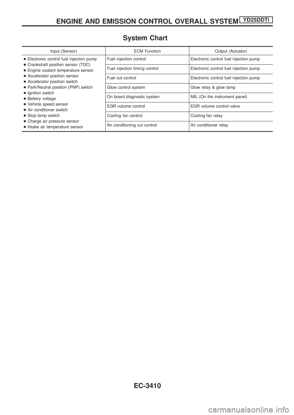
System Chart
Input (Sensor) ECM Function Output (Actuator)
+Electronic control fuel injection pump
+Crankshaft position sensor (TDC)
+Engine coolant temperature sensor
+Accelerator position sensor
+Accelerator position switch
+Park/Neutral position (PNP) switch
+Ignition switch
+Battery voltage
+Vehicle speed sensor
+Air conditioner switch
+Stop lamp switch
+Charge air pressure sensor
+Intake air temperature sensorFuel injection control Electronic control fuel injection pump
Fuel injection timing control Electronic control fuel injection pump
Fuel cut control Electronic control fuel injection pump
Glow control system Glow relay & glow lamp
On board diagnostic system MIL (On the instrument panel)
EGR volume control EGR volume control valve
Cooling fan control Cooling fan relay
Air conditioning cut control Air conditioner relay
ENGINE AND EMISSION CONTROL OVERALL SYSTEMYD25DDTi
EC-3410
Page 438 of 1306
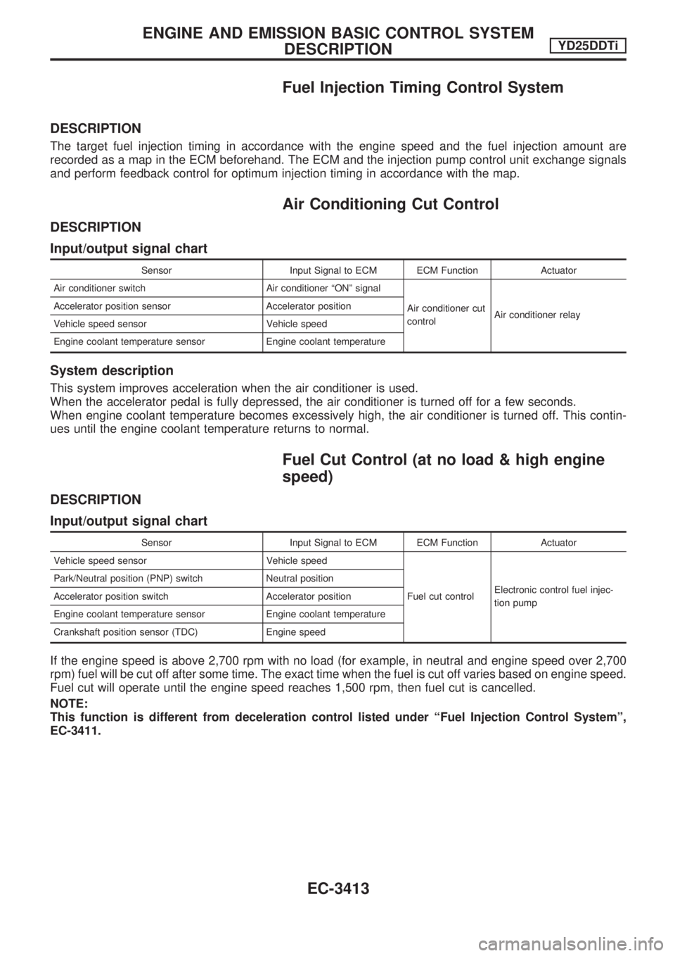
Fuel Injection Timing Control System
DESCRIPTION
The target fuel injection timing in accordance with the engine speed and the fuel injection amount are
recorded as a map in the ECM beforehand. The ECM and the injection pump control unit exchange signals
and perform feedback control for optimum injection timing in accordance with the map.
Air Conditioning Cut Control
DESCRIPTION
Input/output signal chart
Sensor Input Signal to ECM ECM Function Actuator
Air conditioner switch Air conditioner ªONº signal
Air conditioner cut
controlAir conditioner relay Accelerator position sensor Accelerator position
Vehicle speed sensor Vehicle speed
Engine coolant temperature sensor Engine coolant temperature
System description
This system improves acceleration when the air conditioner is used.
When the accelerator pedal is fully depressed, the air conditioner is turned off for a few seconds.
When engine coolant temperature becomes excessively high, the air conditioner is turned off. This contin-
ues until the engine coolant temperature returns to normal.
Fuel Cut Control (at no load & high engine
speed)
DESCRIPTION
Input/output signal chart
Sensor Input Signal to ECM ECM Function Actuator
Vehicle speed sensor Vehicle speed
Fuel cut controlElectronic control fuel injec-
tion pump Park/Neutral position (PNP) switch Neutral position
Accelerator position switch Accelerator position
Engine coolant temperature sensor Engine coolant temperature
Crankshaft position sensor (TDC) Engine speed
If the engine speed is above 2,700 rpm with no load (for example, in neutral and engine speed over 2,700
rpm) fuel will be cut off after some time. The exact time when the fuel is cut off varies based on engine speed.
Fuel cut will operate until the engine speed reaches 1,500 rpm, then fuel cut is cancelled.
NOTE:
This function is different from deceleration control listed under ªFuel Injection Control Systemº,
EC-3411.
ENGINE AND EMISSION BASIC CONTROL SYSTEM
DESCRIPTIONYD25DDTi
EC-3413
Page 1036 of 1306
![NISSAN PICK-UP 2001 Repair Manual REMOVAL
1. Place a pan to catch the oil under the lower part of drain hose
outlet before removing filter body.
2. Using a hexagonal socket wrench [plane-to-plane width: 24
mm (0.94 in)], loosen the fi](/img/5/57372/w960_57372-1035.png "NISSAN PICK-UP 2001 Repair Manual REMOVAL
1. Place a pan to catch the oil under the lower part of drain hose
outlet before removing filter body.
2. Using a hexagonal socket wrench [plane-to-plane width: 24
mm (0.94 in)], loosen the fi")
REMOVAL
1. Place a pan to catch the oil under the lower part of drain hose
outlet before removing filter body.
2. Using a hexagonal socket wrench [plane-to-plane width: 24
mm (0.94 in)], loosen the filter body approximately four turns.
3. Remove the filter body, then remove the oil filter element.
4. Remove the O-ring from the filter body.
+Push the O-ring in one direction, lift the slack part using
fingers, and remove the O-ring from the filter body.
CAUTION:
Do not use wires or flat-bladed screwdrivers etc. as they
may cause damage to the filter body.
INSTALLATION
1. Completely remove all foreign objects adhering to the inside
of the filter body or O-ring mounting area (filter body side and
bracket side).
2. Install the oil filter element and O-ring to the filter body.
+Push the oil filter element into the filter body completely.
3. Install the filter body to the oil filter bracket.
:20-25Nzm (2.0 - 2.6 kg-m, 15 - 18 ft-lb)
4. After warming up the engine, check for engine oil leakage
and oil level.
CAUTION:
Completely wipe clean any engine oil remaining on the fil-
ter body or vehicle.
Changing Engine Coolant
To avoid the danger of being scalded, never change the
coolant when the engine is hot.
Ð DRAINING ENGINE COOLANT Ð
1. Set air conditioning system as follows to prevent coolant from
remaining in the system.
a. Turn ignition switch ON and set temperature controller to
maximum hot position.
b. Wait 10 seconds before turning ignition switch OFF.
2. Open radiator drain plug at the bottom of radiator and
remove radiator cap to drain coolant.
SMA160D
JLC292B OK
SMA161D
ENGINE MAINTENANCEYD25DDTi
Changing Oil Filter (Cont'd)
MA-3014