ad blue NISSAN PRIMERA 1999 Electronic User Guide
[x] Cancel search | Manufacturer: NISSAN, Model Year: 1999, Model line: PRIMERA, Model: NISSAN PRIMERA 1999Pages: 2267, PDF Size: 35.74 MB
Page 1741 of 2267

Main bearing undersize
Unit: mm (in)
Crank journal diameter
STD52.951 - 52.975
(2.0847 - 2.0856)
0.25 (0.0098) undersize52.701 - 52.725
(2.0748 - 2.0758)
Connecting rod bearing undersize
Unit: mm (in)
Crank pin diameter
STDGrade 0 Black49.968 - 49.974
(1.9672 - 1.9675)
Grade 1 Yellow49.961 - 49.968
(1.9670 - 1.9672)
Grade 2 Blue49.954 - 49.961
(1.9667 - 1.9670)
0.08 (0.0031) undersize49.874 - 49.894*
(1.9635 - 1.9643)
0.12 (0.0047) undersize49.834 - 49.854*
(1.9620 - 1.9628)
0.25 (0.0098) undersize49.704 - 49.724*
(1.9568 - 1.9576)
*: Reference value
Bearing clearance
Unit: mm (in)
Main bearing clearance
Standard0.039 - 0.065
(0.0015 - 0.0026)
Connecting rod bearing clearance
Standard0.031 - 0.055
(0.0012 - 0.0022)
TURBOCHARGER
Unit: mm (in)
Rotor shaft
Runout [TIR*] 0.056 - 0.127 (0.0022 - 0.0050)
End play 0.013 - 0.097 (0.0005 - 0.0038)
*: Total indicator reading
MISCELLANEOUS COMPONENTS
Unit: mm (in)
Flywheel
Runout [TIR*] Less than 0.15 (0.0059)
*: Total indicator reading
SERVICE DATA AND SPECIFICATIONS (SDS)CD20T
Inspection and Adjustment (Cont'd)
EM-201
Page 1808 of 2267

Description
Number Item Description
p1Power conditionlThis shows the condition when the system receives battery positive voltage
(can be operated).
p2Fusible link
lThe double line shows that this is a fusible link.
lThe open circle shows current flow in, and the shaded circle shows current
flow out.
p3Fusible link/fuse locationlThis shows the location of the fusible link or fuse in the fusible link or fuse
box. For arrangement, refer to EL section (ªPOWER SUPPLY ROUTINGº).
p4Fuse
lThe single line shows that this is a fuse.
lThe open circle shows current flow in, and the shaded circle shows current
flow out.
p5Current ratinglThis shows the current rating of the fusible link or fuse.
p6Connectors
lThis shows that connectorE3is female and connectorM1is male.
lThe G/R wire is located in the 1A terminal of both connectors.
lTerminal number with an alphanumeric reference (1A, 5B, etc.) indicates that
the connector is an SMJ connector.
p7Optional splicelThe open circle shows that the splice is optional depending on vehicle appli-
cation.
p8SplicelThe shaded circle shows that the splice is always on the vehicle.
p9Page crossinglThis arrow shows that the circuit continues to an adjacent page.
lThe A will match with the A on the preceding or next page.
p10Common connectorlThe dotted lines between terminals show that these terminals are part of the
same connector.
p11Option abbreviationlThis shows that the circuit is optional depending on vehicle application.
p12RelaylThis shows an internal representation of the relay. For details, refer to EL sec-
tion (ªSTANDARDIZED RELAYº).
p13ConnectorslThis shows that the connector is connected to the body or a terminal with bolt
or nut.
p14Wire color
lThis shows a code for the color of the wire.
B = Black BR = Brown
W = White OR = Orange
R = Red P = Pink
G = Green PU = Purple
L = Blue GY = Gray
Y = Yellow SB = Sky Blue
LG = Light Green CH = Dark Brown
DG = Dark Green
When the wire color is striped, the base color is given first, followed by the
stripe color as shown below:
Example: L/W = Blue with White Stripe
p15Option descriptionlThis shows a description of the option abbreviation used on the page.
p16Switch
lThis shows that continuity exists between terminals 1 and 2 when the switch
is in the A position. Continuity exists between terminals 1 and 3 when the
switch is in the B position.
p17Assembly partslConnector terminal in component shows that it is a harness incorporated
assembly.
p18Cell codelThis identifies each page of the wiring diagram by section, system and wiring
diagram page number.
HOW TO READ WIRING DIAGRAMS
GI-13
Page 1857 of 2267
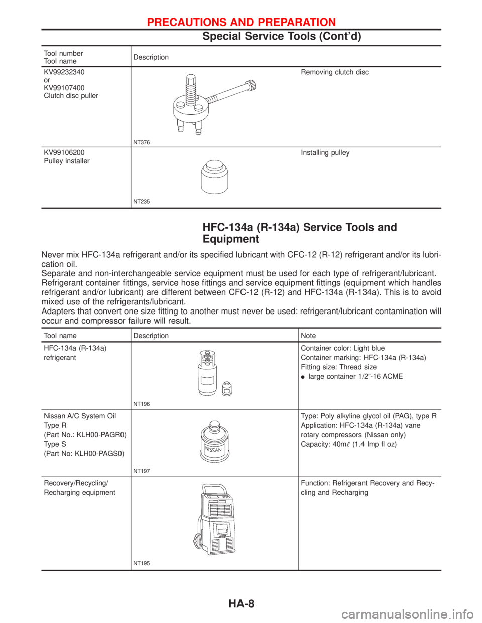
Tool number
Tool nameDescription
KV99232340
or
KV99107400
Clutch disc puller
NT376
Removing clutch disc
KV99106200
Pulley installer
NT235
Installing pulley
HFC-134a (R-134a) Service Tools and
Equipment
Never mix HFC-134a refrigerant and/or its specified lubricant with CFC-12 (R-12) refrigerant and/or its lubri-
cation oil.
Separate and non-interchangeable service equipment must be used for each type of refrigerant/lubricant.
Refrigerant container fittings, service hose fittings and service equipment fittings (equipment which handles
refrigerant and/or lubricant) are different between CFC-12 (R-12) and HFC-134a (R-134a). This is to avoid
mixed use of the refrigerants/lubricant.
Adapters that convert one size fitting to another must never be used: refrigerant/lubricant contamination will
occur and compressor failure will result.
Tool name Description Note
HFC-134a (R-134a)
refrigerant
NT196
Container color: Light blue
Container marking: HFC-134a (R-134a)
Fitting size: Thread size
llarge container 1/2º-16 ACME
Nissan A/C System Oil
Type R
(Part No.: KLH00-PAGR0)
Type S
(Part No: KLH00-PAGS0)
NT197
Type: Poly alkyline glycol oil (PAG), type R
Application: HFC-134a (R-134a) vane
rotary compressors (Nissan only)
Capacity: 40m(1.4 Imp fl oz)
Recovery/Recycling/
Recharging equipment
NT195
Function: Refrigerant Recovery and Recy-
cling and Recharging
PRECAUTIONS AND PREPARATION
Special Service Tools (Cont'd)
HA-8
Page 1858 of 2267
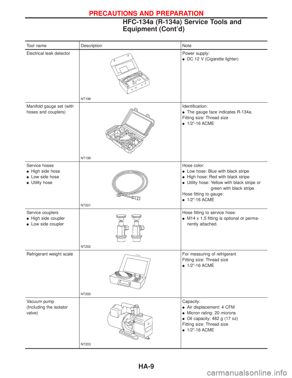
Tool name Description Note
Electrical leak detector
NT198
Power supply:
lDC 12 V (Cigarette lighter)
Manifold gauge set (with
hoses and couplers)
NT199
Identification:
lThe gauge face indicates R-134a.
Fitting size: Thread size
l1/2º-16 ACME
Service hoses
lHigh side hose
lLow side hose
lUtility hose
NT201
Hose color:
lLow hose: Blue with black stripe
lHigh hose: Red with black stripe
lUtility hose: Yellow with black stripe or
green with black stripe
Hose fitting to gauge:
l1/2º-16 ACME
Service couplers
lHigh side coupler
lLow side coupler
NT202
Hose fitting to service hose:
lM14 x 1,5 fitting is optional or perma-
nently attached.
Refrigerant weight scale
NT200
For measuring of refrigerant
Fitting size: Thread size
l1/2º-16 ACME
Vacuum pump
(Including the isolator
valve)
NT203
Capacity:
lAir displacement: 4 CFM
lMicron rating: 20 microns
lOil capacity: 482 g (17 oz)
Fitting size: Thread size
l1/2º-16 ACME
PRECAUTIONS AND PREPARATION
HFC-134a (R-134a) Service Tools and
Equipment (Cont'd)
HA-9
Page 1868 of 2267

Control Operation
FAN CONTROL KNOB
This knob turns the fan ON and OFF, and controls fan speed.
MODE CONTROL KNOB
This knob controls the outlet air flow.
TEMPERATURE CONTROL KNOB
This knob allows adjustment of the temperature of the outlet air.
RECIRCULATION (REC) SWITCH
OFF position:
Outside air is drawn into the passenger compartment.
ON position:
Interior air is recirculated inside the vehicle.
The indicator lamp will also light.
Air Flow
FRESH VENT SYSTEM
This system is controlled by means of the fresh air vent lever which is mechanically linked to the fresh vent
door by the control cable.
Fresh vent air always comes from the center vent in any mode when the fresh air vent lever is set at the
blue dot position.
KHA105 Fan
control knobTemperature
control knobMode
control knobMode
control knobTemperature
control knobFan
control knob
Rear defroster
switchRecirculation
switch
.Rear defroster
switch Recirculation
switch LHD modelsRHD models
KHA064 Fresh air vent
control lever
Set at blue dot positionTo defroster
Heater core
Evaporator
Outside air
To floor To floor
Fresh air vent con-
trol cable
DESCRIPTIONHEATER
HA-19