cooling NISSAN PRIMERA 1999 Electronic Repair Manual
[x] Cancel search | Manufacturer: NISSAN, Model Year: 1999, Model line: PRIMERA, Model: NISSAN PRIMERA 1999Pages: 2267, PDF Size: 35.74 MB
Page 8 of 2267
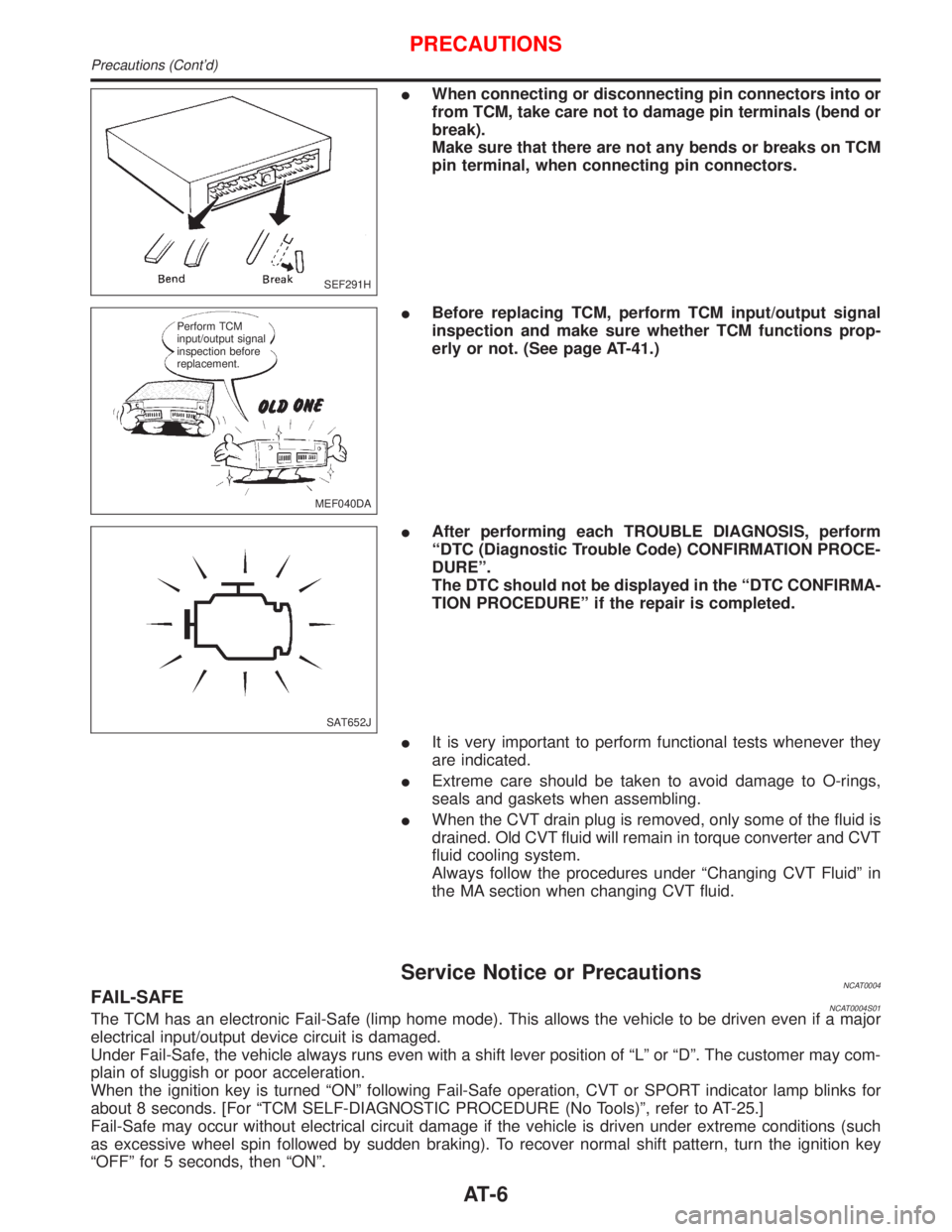
IWhen connecting or disconnecting pin connectors into or
from TCM, take care not to damage pin terminals (bend or
break).
Make sure that there are not any bends or breaks on TCM
pin terminal, when connecting pin connectors.
IBefore replacing TCM, perform TCM input/output signal
inspection and make sure whether TCM functions prop-
erly or not. (See page AT-41.)
IAfter performing each TROUBLE DIAGNOSIS, perform
ªDTC (Diagnostic Trouble Code) CONFIRMATION PROCE-
DUREº.
The DTC should not be displayed in the ªDTC CONFIRMA-
TION PROCEDUREº if the repair is completed.
IIt is very important to perform functional tests whenever they
are indicated.
IExtreme care should be taken to avoid damage to O-rings,
seals and gaskets when assembling.
IWhen the CVT drain plug is removed, only some of the fluid is
drained. Old CVT fluid will remain in torque converter and CVT
fluid cooling system.
Always follow the procedures under ªChanging CVT Fluidº in
the MA section when changing CVT fluid.
Service Notice or PrecautionsNCAT0004FAIL-SAFENCAT0004S01The TCM has an electronic Fail-Safe (limp home mode). This allows the vehicle to be driven even if a major
electrical input/output device circuit is damaged.
Under Fail-Safe, the vehicle always runs even with a shift lever position of ªLº or ªDº. The customer may com-
plain of sluggish or poor acceleration.
When the ignition key is turned ªONº following Fail-Safe operation, CVT or SPORT indicator lamp blinks for
about 8 seconds. [For ªTCM SELF-DIAGNOSTIC PROCEDURE (No Tools)º, refer to AT-25.]
Fail-Safe may occur without electrical circuit damage if the vehicle is driven under extreme conditions (such
as excessive wheel spin followed by sudden braking). To recover normal shift pattern, turn the ignition key
ªOFFº for 5 seconds, then ªONº.
SEF291H
MEF040DA Perform TCM
input/output signal
inspection before
replacement.
SAT652J
PRECAUTIONS
Precautions (Cont'd)
AT-6
Page 295 of 2267
ENGINE CONTROL SYSTEM
SECTION
EC
CONTENTS
CD20T
PRECAUTIONS AND PREPARATION.......................... 3
Special Service Tools ................................................ 3
Engine Fuel & Emission Control System .................. 5
Supplemental Restraint System (SRS)²AIR
BAG²and²SEAT BELT PRE-TENSIONER²............. 6
Precautions for On Board Diagnostic (OBD)
System of Engine ...................................................... 6
Precautions ................................................................ 7
ENGINE AND EMISSION CONTROL OVERALL
SYSTEM......................................................................... 9
Engine Control Module Component Parts
Location ..................................................................... 9
Circuit Diagram ......................................................... 11
System Diagram ...................................................... 12
Vacuum Hose Drawing ............................................ 13
System Chart ........................................................... 14
ENGINE AND EMISSION BASIC CONTROL
SYSTEM DESCRIPTION............................................. 15
Glow Control System ............................................... 15
Fuel Injection System .............................................. 15
Fuel Injection Timing System .................................. 18
Air Conditioning Cut Control .................................... 20
Cooling Fan Control................................................. 20
CRANKCASE VENTILATION SYSTEM...................... 21
Description ............................................................... 21
Blow-by Control Valve ............................................. 21
Ventilation Hose ....................................................... 21
INJECTION NOZZLE................................................... 22
Removal and Installation ......................................... 22
Test and Adjustment ................................................ 22
ELECTRONIC FUEL INJECTION PUMP.................... 24
Removal ................................................................... 24
Installation ................................................................ 25Disassembly and Assembly ..................................... 26
ON BOARD DIAGNOSTIC SYSTEM
DESCRIPTION............................................................. 27
CONSULT-II ............................................................. 27
TROUBLE DIAGNOSIS - INTRODUCTION................ 33
Introduction .............................................................. 33
Diagnostic Worksheet .............................................. 34
TROUBLE DIAGNOSIS - WORK FLOW.................... 35
Work Flow ................................................................ 35
Description for Work Flow ....................................... 36
TROUBLE DIAGNOSIS - BASIC INSPECTION......... 37
Basic Inspection....................................................... 37
TROUBLE DIAGNOSIS - GENERAL
DESCRIPTION............................................................. 39
Diagnostic Trouble Chart ......................................... 39
Symptom Matrix Chart ............................................. 47
CONSULT-II Reference Value in Data Monitor
Mode ........................................................................ 50
Major Sensor Reference Graph in Data Monitor
Mode ........................................................................ 51
ECM Terminals and Reference Value ..................... 52
TROUBLE DIAGNOSIS FOR POWER SUPPLY........ 59
Main Power Supply and Ground Circuit .................. 59
TROUBLE DIAGNOSIS 1............................................ 62
Mass Air Flow Sensor (MAFS) ................................ 62
TROUBLE DIAGNOSIS 2............................................ 66
Engine Coolant Temperature (ECT) Sensor ........... 66
TROUBLE DIAGNOSIS 3............................................ 70
Vehicle Speed Sensor (VSS) .................................. 70
TROUBLE DIAGNOSIS 4............................................ 74
Control Sleeve Position Sensor (CSPS) ................. 74
TROUBLE DIAGNOSIS 5............................................ 78
Electric Governor ..................................................... 78
TROUBLE DIAGNOSIS 6............................................ 82
EC
Page 296 of 2267
Injection Timing Control Valve ................................. 82
TROUBLE DIAGNOSIS 7............................................ 86
Engine Control Module (ECM) ................................ 86
TROUBLE DIAGNOSIS 8............................................ 87
Cooling Fan (Overheat) ........................................... 87
TROUBLE DIAGNOSIS 9............................................ 97
Needle Lift Sensor (NLS) ........................................ 97
TROUBLE DIAGNOSIS 10........................................ 100
Fuel Cut Solenoid Valve ........................................ 100
TROUBLE DIAGNOSIS 11........................................ 104
Fuel Temperature Sensor (FTS)............................ 104
TROUBLE DIAGNOSIS 12........................................ 108
Accelerator Position Sensor & Switch ................... 108
TROUBLE DIAGNOSIS 13......................................... 114
Crankshaft Position Sensor (TDC) ......................... 114
TROUBLE DIAGNOSES 14....................................... 118
Glow Control System .............................................. 118TROUBLE DIAGNOSES 15...................................... 126
Air Conditioner Cut Control ................................... 126
TROUBLE DIAGNOSES 16...................................... 129
EGRC-Solenoid Valve ........................................... 129
TROUBLE DIAGNOSES 17...................................... 136
Brake Switch .......................................................... 136
TROUBLE DIAGNOSES 18...................................... 140
ECM Relay............................................................. 140
TROUBLE DIAGNOSES 19...................................... 141
MI & Data Link Connectors ................................... 141
TROUBLE DIAGNOSES 20...................................... 145
Start Signal ............................................................ 145
SERVICE DATA AND SPECIFICATIONS (SDS)...... 147
General Specifications ........................................... 147
Injection Nozzle ..................................................... 147
Inspection and Adjustment .................................... 147
When you read wiring diagrams:
lRead GI section, ªHOW TO READ WIRING DIAGRAMSº.
lSee EL section, ªPOWER SUPPLY ROUTINGº for power distribution circuit.
lSee EL section for NATS information and wiring diagram.
When you perform trouble diagnoses, read GI section, ªHOW TO FOLLOW FLOW CHART
IN TROUBLE DIAGNOSESº and ªHOW TO PERFORM EFFICIENT DIAGNOSIS FOR AN
ELECTRICAL INCIDENTº.
For clarification of system component abbreviations and terminology read GI section
ªSAE J1930 TERMINOLOGY LISTº.
EC-2
Page 308 of 2267
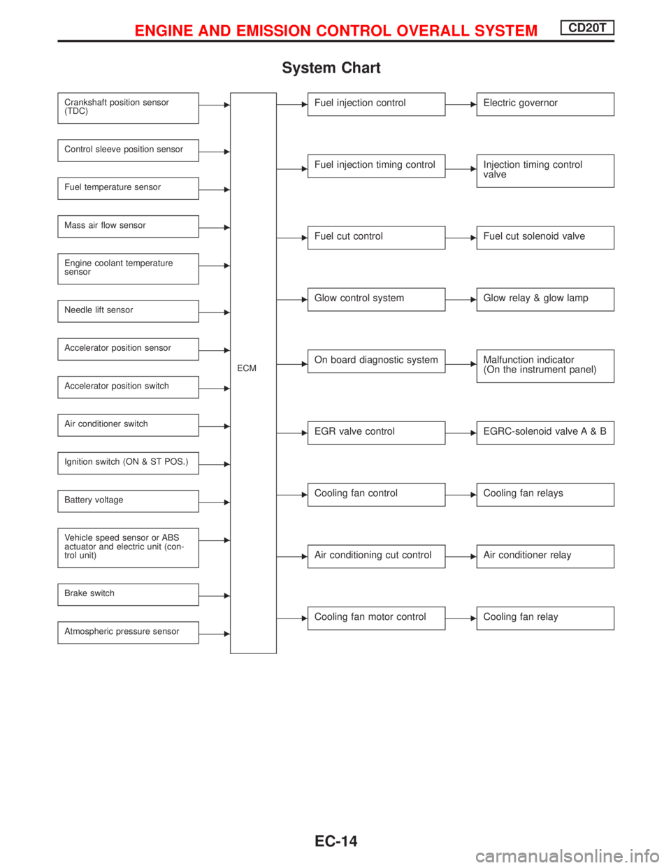
System Chart
Crankshaft position sensor
(TDC)E
ECM
Control sleeve position sensorE
Fuel temperature sensorE
Mass air flow sensorE
Engine coolant temperature
sensorE
Needle lift sensorE
Accelerator position sensorE
Accelerator position switchE
Air conditioner switchE
Ignition switch (ON & ST POS.)E
Battery voltageE
Vehicle speed sensor or ABS
actuator and electric unit (con-
trol unit)E
Brake switchE
Atmospheric pressure sensorE
EFuel injection controlEElectric governor
EFuel injection timing controlEInjection timing control
valve
EFuel cut controlEFuel cut solenoid valve
EGlow control systemEGlow relay & glow lamp
EOn board diagnostic systemEMalfunction indicator
(On the instrument panel)
EEGR valve controlEEGRC-solenoid valve A & B
ECooling fan controlECooling fan relays
EAir conditioning cut controlEAir conditioner relay
ECooling fan motor controlECooling fan relay
ENGINE AND EMISSION CONTROL OVERALL SYSTEMCD20T
EC-14
Page 314 of 2267
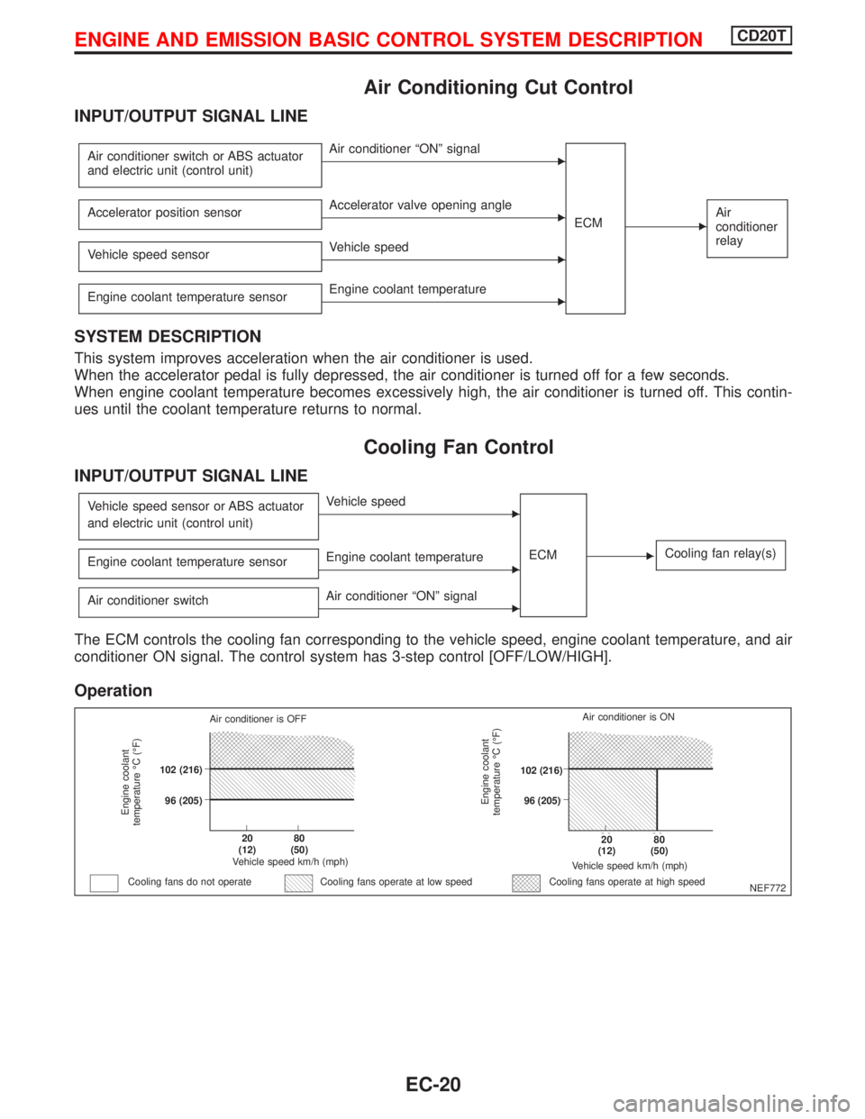
Air Conditioning Cut Control
INPUT/OUTPUT SIGNAL LINE
Air conditioner switch or ABS actuator
and electric unit (control unit)EAir conditioner ªONº signal
ECM
EAir
conditioner
relayAccelerator position sensorEAccelerator valve opening angle
Vehicle speed sensor
EVehicle speed
Engine coolant temperature sensor
EEngine coolant temperature
SYSTEM DESCRIPTION
This system improves acceleration when the air conditioner is used.
When the accelerator pedal is fully depressed, the air conditioner is turned off for a few seconds.
When engine coolant temperature becomes excessively high, the air conditioner is turned off. This contin-
ues until the coolant temperature returns to normal.
Cooling Fan Control
INPUT/OUTPUT SIGNAL LINE
Vehicle speed sensor or ABS actuator
and electric unit (control unit)EVehicle speed
ECM
ECooling fan relay(s)Engine coolant temperature sensorEEngine coolant temperature
Air conditioner switch
EAir conditioner ªONº signal
The ECM controls the cooling fan corresponding to the vehicle speed, engine coolant temperature, and air
conditioner ON signal. The control system has 3-step control [OFF/LOW/HIGH].
Operation
NEF772
Engine coolant
temperature ÉC (ÉF)
Air conditioner is OFF
.102 (216)
.96 (205)
.20
(12).80
(50)
Vehicle speed km/h (mph)
Cooling fans do not operateCooling fans operate at high speed
Engine coolant
temperature ÉC (ÉF)
Vehicle speed km/h (mph)
.20
(12).80
(50)
.102 (216)
.96 (205)Air conditioner is ON
Cooling fans operate at low speed
ENGINE AND EMISSION BASIC CONTROL SYSTEM DESCRIPTIONCD20T
EC-20
Page 322 of 2267
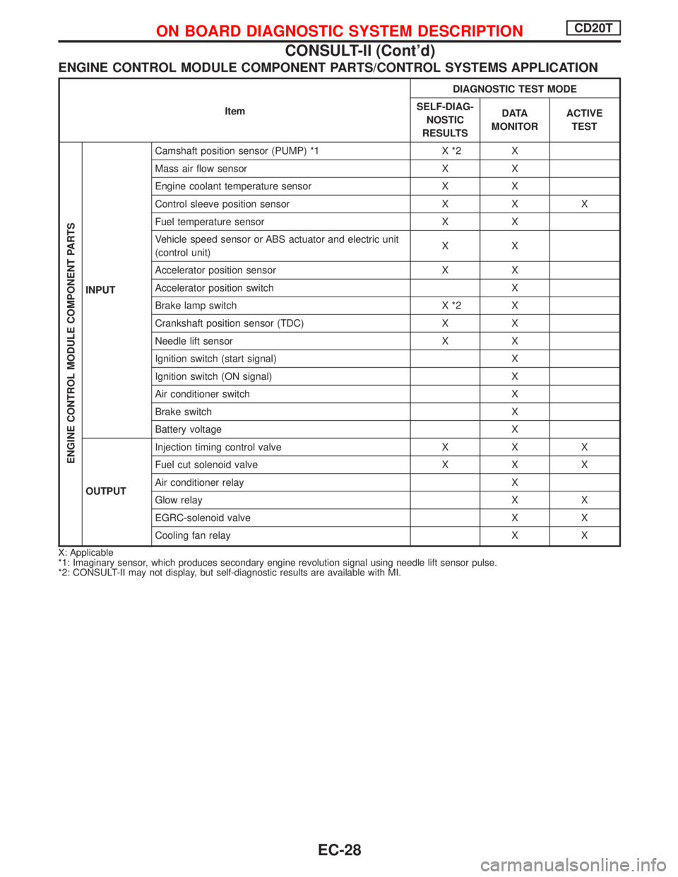
ENGINE CONTROL MODULE COMPONENT PARTS/CONTROL SYSTEMS APPLICATION
ItemDIAGNOSTIC TEST MODE
SELF-DIAG-
NOSTIC
RESULTSD ATA
MONITORACTIVE
TEST
ENGINE CONTROL MODULE COMPONENT PARTS
INPUTCamshaft position sensor (PUMP) *1 X *2 X
Mass air flow sensor X X
Engine coolant temperature sensor X X
Control sleeve position sensor X X X
Fuel temperature sensor X X
Vehicle speed sensor or ABS actuator and electric unit
(control unit)XX
Accelerator position sensor X X
Accelerator position switch X
Brake lamp switch X *2 X
Crankshaft position sensor (TDC) X X
Needle lift sensor X X
Ignition switch (start signal) X
Ignition switch (ON signal) X
Air conditioner switch X
Brake switch X
Battery voltage X
OUTPUTInjection timing control valve X X X
Fuel cut solenoid valve X X X
Air conditioner relay X
Glow relay X X
EGRC-solenoid valve X X
Cooling fan relay X X
X: Applicable
*1: Imaginary sensor, which produces secondary engine revolution signal using needle lift sensor pulse.
*2: CONSULT-II may not display, but self-diagnostic results are available with MI.
ON BOARD DIAGNOSTIC SYSTEM DESCRIPTIONCD20T
CONSULT-II (Cont'd)
EC-28
Page 324 of 2267
![NISSAN PRIMERA 1999 Electronic Repair Manual Monitored item
[Unit]ECM
input
signalsMain
signalsDescription Remarks
FUEL CUT S/V
[ON/OFF]
lThe control condition of the fuel cut
solenoid valve (determined by ECM
according to the input signal) is i NISSAN PRIMERA 1999 Electronic Repair Manual Monitored item
[Unit]ECM
input
signalsMain
signalsDescription Remarks
FUEL CUT S/V
[ON/OFF]
lThe control condition of the fuel cut
solenoid valve (determined by ECM
according to the input signal) is i](/img/5/57377/w960_57377-323.png)
Monitored item
[Unit]ECM
input
signalsMain
signalsDescription Remarks
FUEL CUT S/V
[ON/OFF]
lThe control condition of the fuel cut
solenoid valve (determined by ECM
according to the input signal) is indi-
cated.
lOFF ... Fuel cut solenoid valve is not
operating.
ON ... Fuel cut solenoid valve is oper-
ating.
lWhen the fuel cut solenoid valve is not
operating, fuel supply is shut off.
AIR COND RLY
[ON/OFF]
q
lThe air conditioner relay control condi-
tion (determined by ECM according to
the input signal) is indicated.
GLOW RLY
[ON/OFF]
q
lThe glow relay control condition (deter-
mined by ECM according to the input
signal) is displayed.
COOLING FAN
[LOW/HI/OFF]
q
lIndicates the control condition of the
cooling fans (determined by ECM
according to the input signal).
lLOW ... Operates at low speed.
HI ... Operates at high speed.
OFF ... Stopped.
EGRC SOL/V A
[ON/OFF]
lThe control condition of the EGRC-
solenoid valve (determined by ECM
according to the input signal) is indi-
cated.
lOFF ... EGRC-solenoid valve is not
operating.
ON ... EGRC-solenoid valve is oper-
ating.
ON BOARD DIAGNOSTIC SYSTEM DESCRIPTIONCD20T
CONSULT-II (Cont'd)
EC-30
Page 325 of 2267
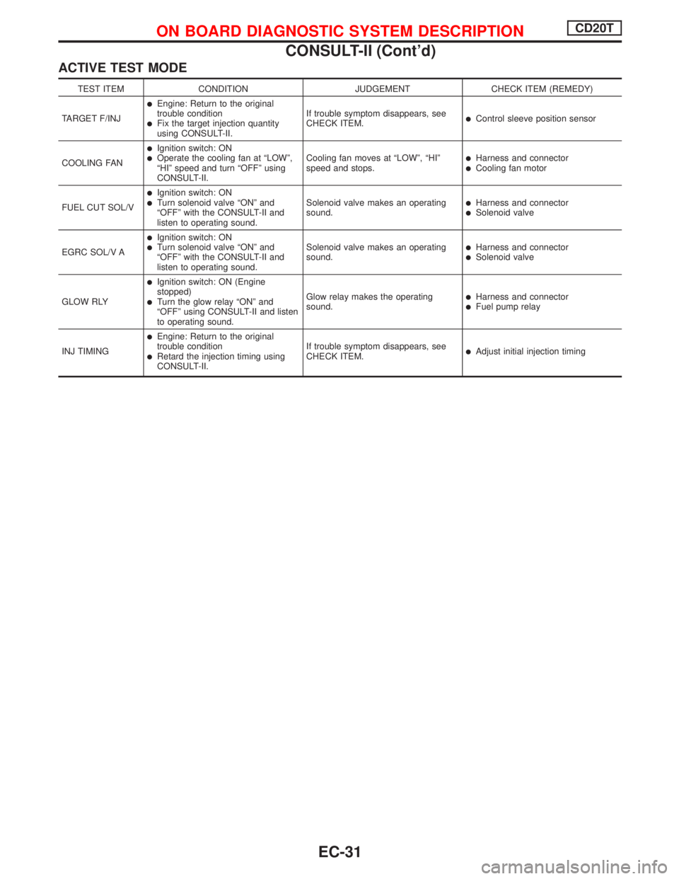
ACTIVE TEST MODE
TEST ITEM CONDITION JUDGEMENT CHECK ITEM (REMEDY)
TARGET F/INJ
lEngine: Return to the original
trouble condition
lFix the target injection quantity
using CONSULT-II.If trouble symptom disappears, see
CHECK ITEM.lControl sleeve position sensor
COOLING FAN
lIgnition switch: ONlOperate the cooling fan at ªLOWº,
ªHIº speed and turn ªOFFº using
CONSULT-II.Cooling fan moves at ªLOWº, ªHIº
speed and stops.lHarness and connectorlCooling fan motor
FUEL CUT SOL/V
lIgnition switch: ONlTurn solenoid valve ªONº and
ªOFFº with the CONSULT-II and
listen to operating sound.Solenoid valve makes an operating
sound.lHarness and connectorlSolenoid valve
EGRC SOL/V A
lIgnition switch: ONlTurn solenoid valve ªONº and
ªOFFº with the CONSULT-II and
listen to operating sound.Solenoid valve makes an operating
sound.lHarness and connectorlSolenoid valve
GLOW RLY
lIgnition switch: ON (Engine
stopped)
lTurn the glow relay ªONº and
ªOFFº using CONSULT-II and listen
to operating sound.Glow relay makes the operating
sound.lHarness and connectorlFuel pump relay
INJ TIMING
lEngine: Return to the original
trouble condition
lRetard the injection timing using
CONSULT-II.If trouble symptom disappears, see
CHECK ITEM.lAdjust initial injection timing
ON BOARD DIAGNOSTIC SYSTEM DESCRIPTIONCD20T
CONSULT-II (Cont'd)
EC-31
Page 328 of 2267
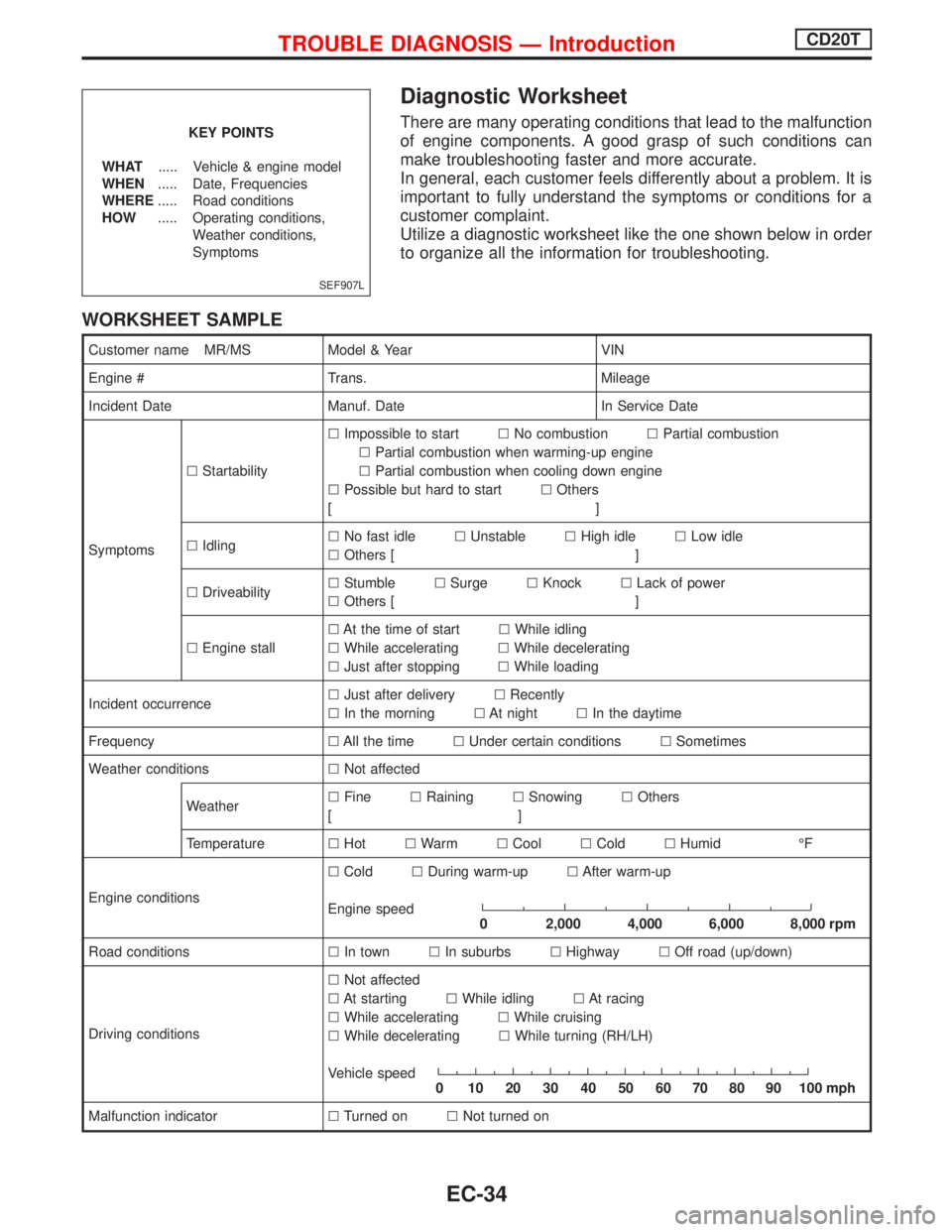
Diagnostic Worksheet
There are many operating conditions that lead to the malfunction
of engine components. A good grasp of such conditions can
make troubleshooting faster and more accurate.
In general, each customer feels differently about a problem. It is
important to fully understand the symptoms or conditions for a
customer complaint.
Utilize a diagnostic worksheet like the one shown below in order
to organize all the information for troubleshooting.
WORKSHEET SAMPLE
Customer name MR/MS Model & Year VIN
Engine # Trans. Mileage
Incident Date Manuf. Date In Service Date
SymptomslStartabilitylImpossible to startlNo combustionlPartial combustion
lPartial combustion when warming-up engine
lPartial combustion when cooling down engine
lPossible but hard to startlOthers
[]
lIdlinglNo fast idlelUnstablelHigh idlelLow idle
lOthers [ ]
lDriveabilitylStumblelSurgelKnocklLack of power
lOthers [ ]
lEngine stalllAt the time of startlWhile idling
lWhile acceleratinglWhile decelerating
lJust after stoppinglWhile loading
Incident occurrencelJust after deliverylRecently
lIn the morninglAt nightlIn the daytime
FrequencylAll the timelUnder certain conditionslSometimes
Weather conditionslNot affected
WeatherlFinelRaininglSnowinglOthers
[]
TemperaturelHotlWarmlCoollColdlHumid ÉF
Engine conditionslColdlDuring warm-uplAfter warm-up
Engine speed
0 2,000 4,000 6,000 8,000 rpm
Road conditionslIn townlIn suburbslHighwaylOff road (up/down)
Driving conditionslNot affected
lAt startinglWhile idlinglAt racing
lWhile acceleratinglWhile cruising
lWhile deceleratinglWhile turning (RH/LH)
Vehicle speed
0 102030405060708090100mph
Malfunction indicatorlTurned onlNot turned on
SEF907L
KEY POINTS
WHAT..... Vehicle & engine model
WHEN..... Date, Frequencies
WHERE..... Road conditions
HOW..... Operating conditions,
Weather conditions,
Symptoms
TROUBLE DIAGNOSIS Ð IntroductionCD20T
EC-34
Page 335 of 2267
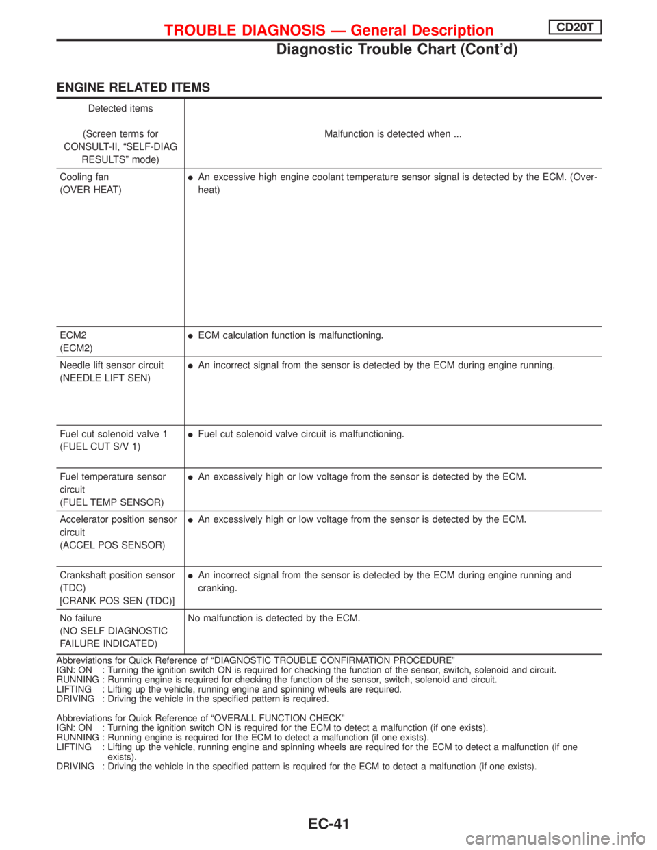
ENGINE RELATED ITEMS
Detected items
(Screen terms for
CONSULT-II, ªSELF-DIAG
RESULTSº mode)Malfunction is detected when ...
Cooling fan
(OVER HEAT)
lAn excessive high engine coolant temperature sensor signal is detected by the ECM. (Over-
heat)
ECM2
(ECM2)
lECM calculation function is malfunctioning.
Needle lift sensor circuit
(NEEDLE LIFT SEN)
lAn incorrect signal from the sensor is detected by the ECM during engine running.
Fuel cut solenoid valve 1
(FUEL CUT S/V 1)
lFuel cut solenoid valve circuit is malfunctioning.
Fuel temperature sensor
circuit
(FUEL TEMP SENSOR)
lAn excessively high or low voltage from the sensor is detected by the ECM.
Accelerator position sensor
circuit
(ACCEL POS SENSOR)
lAn excessively high or low voltage from the sensor is detected by the ECM.
Crankshaft position sensor
(TDC)
[CRANK POS SEN (TDC)]
lAn incorrect signal from the sensor is detected by the ECM during engine running and
cranking.
No failure
(NO SELF DIAGNOSTIC
FAILURE INDICATED)No malfunction is detected by the ECM.
Abbreviations for Quick Reference of ªDIAGNOSTIC TROUBLE CONFIRMATION PROCEDUREº
IGN: ON : Turning the ignition switch ON is required for checking the function of the sensor, switch, solenoid and circuit.
RUNNING : Running engine is required for checking the function of the sensor, switch, solenoid and circuit.
LIFTING : Lifting up the vehicle, running engine and spinning wheels are required.
DRIVING : Driving the vehicle in the specified pattern is required.
Abbreviations for Quick Reference of ªOVERALL FUNCTION CHECKº
IGN: ON : Turning the ignition switch ON is required for the ECM to detect a malfunction (if one exists).
RUNNING : Running engine is required for the ECM to detect a malfunction (if one exists).
LIFTING : Lifting up the vehicle, running engine and spinning wheels are required for the ECM to detect a malfunction (if one
exists).
DRIVING : Driving the vehicle in the specified pattern is required for the ECM to detect a malfunction (if one exists).
TROUBLE DIAGNOSIS Ð General DescriptionCD20T
Diagnostic Trouble Chart (Cont'd)
EC-41