ABS NISSAN PRIMERA 1999 Electronic Repair Manual
[x] Cancel search | Manufacturer: NISSAN, Model Year: 1999, Model line: PRIMERA, Model: NISSAN PRIMERA 1999Pages: 2267, PDF Size: 35.74 MB
Page 14 of 2267
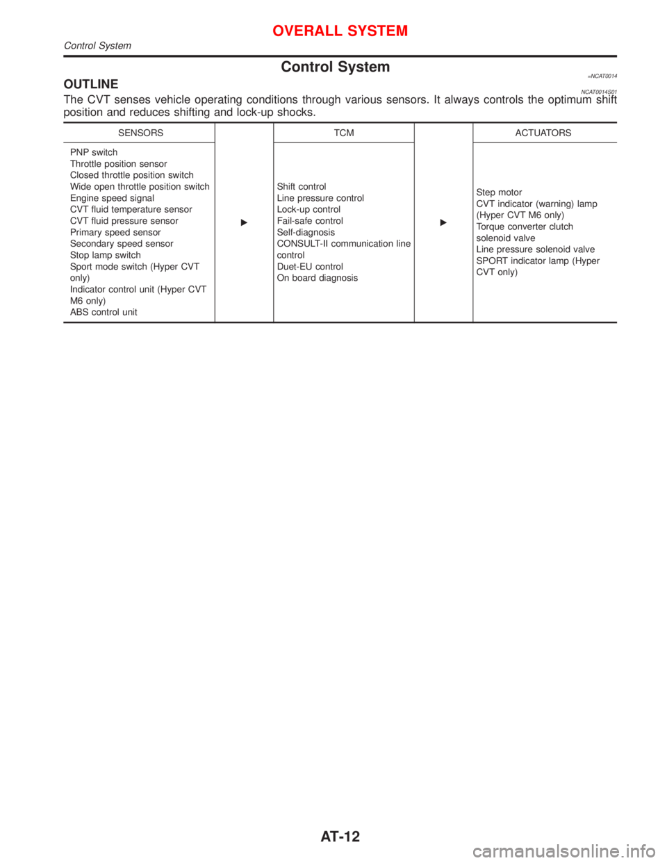
Control System=NCAT0014OUTLINENCAT0014S01The CVT senses vehicle operating conditions through various sensors. It always controls the optimum shift
position and reduces shifting and lock-up shocks.
SENSORS
ETCM
EACTUATORS
PNP switch
Throttle position sensor
Closed throttle position switch
Wide open throttle position switch
Engine speed signal
CVT fluid temperature sensor
CVT fluid pressure sensor
Primary speed sensor
Secondary speed sensor
Stop lamp switch
Sport mode switch (Hyper CVT
only)
Indicator control unit (Hyper CVT
M6 only)
ABS control unitShift control
Line pressure control
Lock-up control
Fail-safe control
Self-diagnosis
CONSULT-II communication line
control
Duet-EU control
On board diagnosisStep motor
CVT indicator (warning) lamp
(Hyper CVT M6 only)
Torque converter clutch
solenoid valve
Line pressure solenoid valve
SPORT indicator lamp (Hyper
CVT only)
OVERALL SYSTEM
Control System
AT-12
Page 15 of 2267
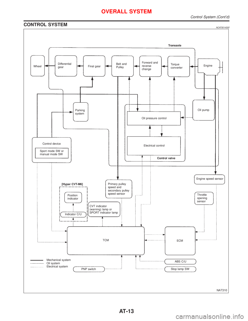
CONTROL SYSTEMNCAT0014S02
NAT310 WheelDifferential
gearFinal gearBelt and
PulleyForward and
reverse
changeTorque
converterEngine Transaxle
Oil pump
Oil pressure control Parking
system
Control device
Sport mode SW or
manual mode SWElectrical control
Control valve
Primary pulley
speed and
secondary pulley
speed sensor
CVT indicator
(warning) lamp or
SPORT indicator lamp [Hyper CVT-M6]
Position
indicator
Indicator C/U
TCM
Mechanical system
Oil system
Electrical system
Stop lamp SWABS C/UECMThrottle
opening
sensor Engine speed sensor
PNP switch
OVERALL SYSTEM
Control System (Cont'd)
AT-13
Page 16 of 2267
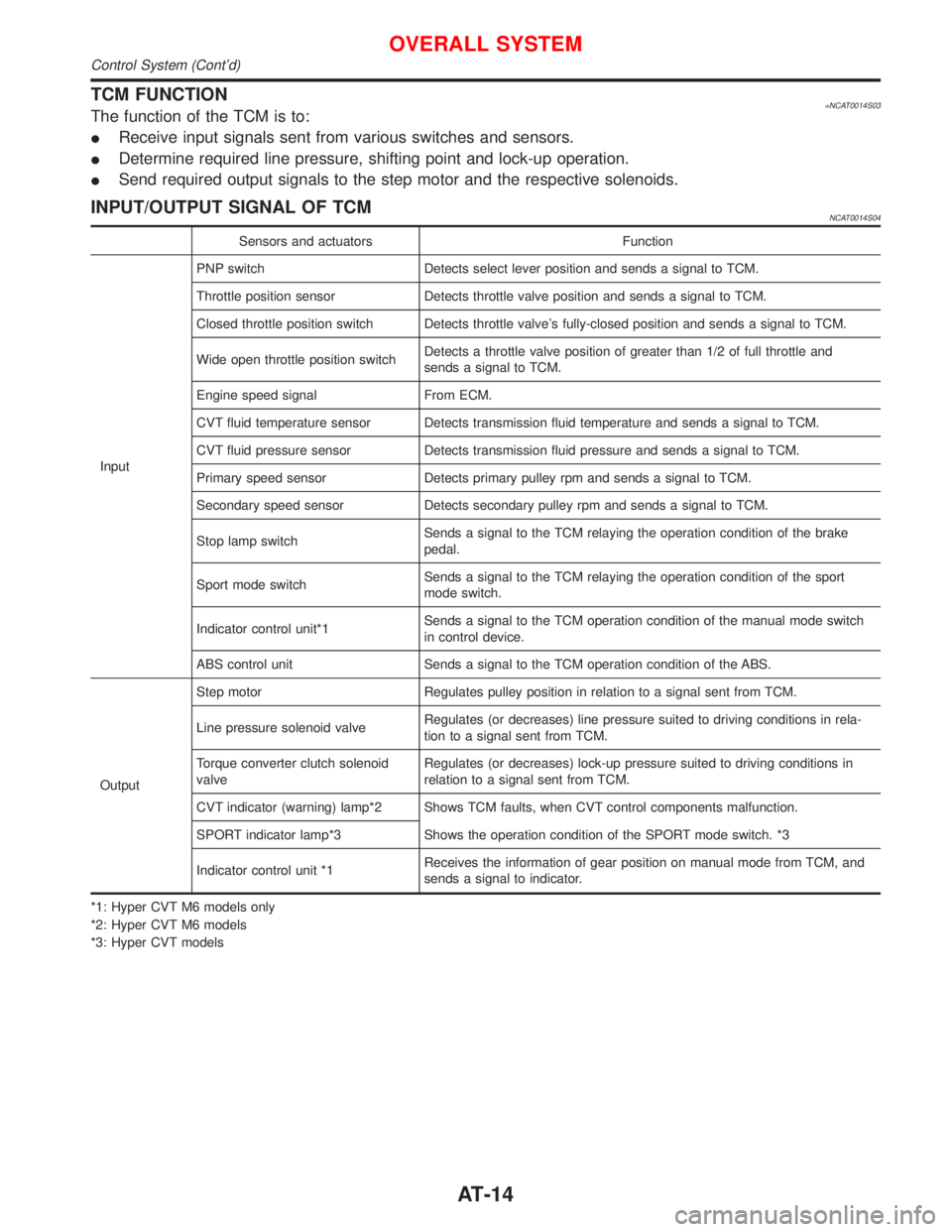
TCM FUNCTION=NCAT0014S03The function of the TCM is to:
IReceive input signals sent from various switches and sensors.
IDetermine required line pressure, shifting point and lock-up operation.
ISend required output signals to the step motor and the respective solenoids.
INPUT/OUTPUT SIGNAL OF TCMNCAT0014S04
Sensors and actuators Function
InputPNP switch Detects select lever position and sends a signal to TCM.
Throttle position sensor Detects throttle valve position and sends a signal to TCM.
Closed throttle position switch Detects throttle valve's fully-closed position and sends a signal to TCM.
Wide open throttle position switchDetects a throttle valve position of greater than 1/2 of full throttle and
sends a signal to TCM.
Engine speed signal From ECM.
CVT fluid temperature sensor Detects transmission fluid temperature and sends a signal to TCM.
CVT fluid pressure sensor Detects transmission fluid pressure and sends a signal to TCM.
Primary speed sensor Detects primary pulley rpm and sends a signal to TCM.
Secondary speed sensor Detects secondary pulley rpm and sends a signal to TCM.
Stop lamp switchSends a signal to the TCM relaying the operation condition of the brake
pedal.
Sport mode switchSends a signal to the TCM relaying the operation condition of the sport
mode switch.
Indicator control unit*1Sends a signal to the TCM operation condition of the manual mode switch
in control device.
ABS control unit Sends a signal to the TCM operation condition of the ABS.
OutputStep motor Regulates pulley position in relation to a signal sent from TCM.
Line pressure solenoid valveRegulates (or decreases) line pressure suited to driving conditions in rela-
tion to a signal sent from TCM.
Torque converter clutch solenoid
valveRegulates (or decreases) lock-up pressure suited to driving conditions in
relation to a signal sent from TCM.
CVT indicator (warning) lamp*2 Shows TCM faults, when CVT control components malfunction.
SPORT indicator lamp*3 Shows the operation condition of the SPORT mode switch. *3
Indicator control unit *1Receives the information of gear position on manual mode from TCM, and
sends a signal to indicator.
*1: Hyper CVT M6 models only
*2: Hyper CVT M6 models
*3: Hyper CVT models
OVERALL SYSTEM
Control System (Cont'd)
AT-14
Page 24 of 2267
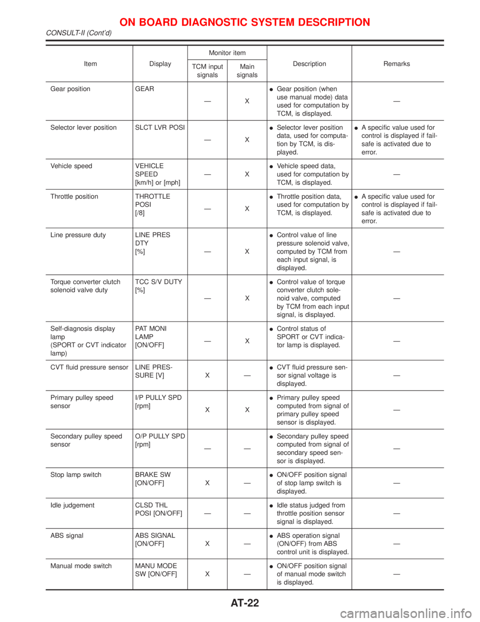
Item DisplayMonitor item
Description Remarks
TCM input
signalsMain
signals
Gear position GEAR
ÐXIGear position (when
use manual mode) data
used for computation by
TCM, is displayed.Ð
Selector lever position SLCT LVR POSI
ÐXISelector lever position
data, used for computa-
tion by TCM, is dis-
played.IA specific value used for
control is displayed if fail-
safe is activated due to
error.
Vehicle speed VEHICLE
SPEED
[km/h] or [mph]ÐXIVehicle speed data,
used for computation by
TCM, is displayed.Ð
Throttle position THROTTLE
POSI
[/8]ÐXIThrottle position data,
used for computation by
TCM, is displayed.IA specific value used for
control is displayed if fail-
safe is activated due to
error.
Line pressure duty LINE PRES
DTY
[%] Ð XIControl value of line
pressure solenoid valve,
computed by TCM from
each input signal, is
displayed.Ð
Torque converter clutch
solenoid valve dutyTCC S/V DUTY
[%]
ÐXIControl value of torque
converter clutch sole-
noid valve, computed
by TCM from each input
signal, is displayed.Ð
Self-diagnosis display
lamp
(SPORT or CVT indicator
lamp)PAT MONI
LAMP
[ON/OFF]ÐXIControl status of
SPORT or CVT indica-
tor lamp is displayed.Ð
CVT fluid pressure sensor LINE PRES-
SURE [V] X ÐICVT fluid pressure sen-
sor signal voltage is
displayed.Ð
Primary pulley speed
sensorI/P PULLY SPD
[rpm]
XXIPrimary pulley speed
computed from signal of
primary pulley speed
sensor is displayed.Ð
Secondary pulley speed
sensorO/P PULLY SPD
[rpm]
ÐÐISecondary pulley speed
computed from signal of
secondary speed sen-
sor is displayed.Ð
Stop lamp switch BRAKE SW
[ON/OFF] X ÐION/OFF position signal
of stop lamp switch is
displayed.Ð
Idle judgement CLSD THL
POSI [ON/OFF] Ð ÐIIdle status judged from
throttle position sensor
signal is displayed.Ð
ABS signal ABS SIGNAL
[ON/OFF] X ÐIABS operation signal
(ON/OFF) from ABS
control unit is displayed.Ð
Manual mode switch MANU MODE
SW [ON/OFF] X ÐION/OFF position signal
of manual mode switch
is displayed.Ð
ON BOARD DIAGNOSTIC SYSTEM DESCRIPTION
CONSULT-II (Cont'd)
AT-22
Page 44 of 2267
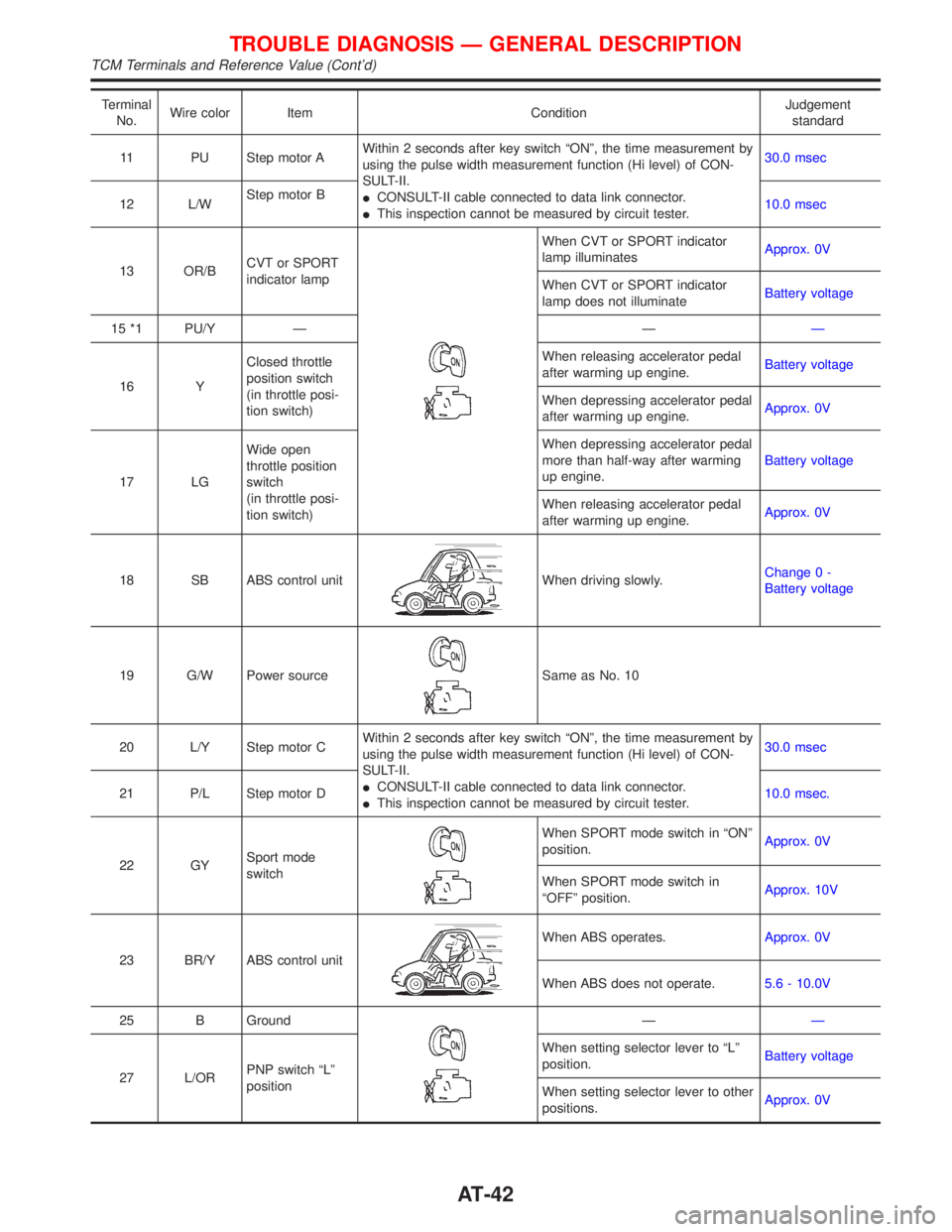
Terminal
No.Wire color Item ConditionJudgement
standard
11 PU Step motor AWithin 2 seconds after key switch ªONº, the time measurement by
using the pulse width measurement function (Hi level) of CON-
SULT-II.
ICONSULT-II cable connected to data link connector.
IThis inspection cannot be measured by circuit tester.30.0 msec
12 L/WStep motor B
10.0 msec
13 OR/BCVT or SPORT
indicator lamp
When CVT or SPORT indicator
lamp illuminatesApprox. 0V
When CVT or SPORT indicator
lamp does not illuminateBattery voltage
15 *1 PU/Y Ð ÐÐ
16 YClosed throttle
position switch
(in throttle posi-
tion switch)When releasing accelerator pedal
after warming up engine.Battery voltage
When depressing accelerator pedal
after warming up engine.Approx. 0V
17 LGWide open
throttle position
switch
(in throttle posi-
tion switch)When depressing accelerator pedal
more than half-way after warming
up engine.Battery voltage
When releasing accelerator pedal
after warming up engine.Approx. 0V
18 SB ABS control unit
When driving slowly.Change 0 -
Battery voltage
19 G/W Power source
Same as No. 10
20 L/Y Step motor CWithin 2 seconds after key switch ªONº, the time measurement by
using the pulse width measurement function (Hi level) of CON-
SULT-II.
ICONSULT-II cable connected to data link connector.
IThis inspection cannot be measured by circuit tester.30.0 msec
21 P/L Step motor D10.0 msec.
22 GYSport mode
switch
When SPORT mode switch in ªONº
position.Approx. 0V
When SPORT mode switch in
ªOFFº position.Approx. 10V
23 BR/Y ABS control unit
When ABS operates.Approx. 0V
When ABS does not operate.5.6 - 10.0V
25 B Ground
ÐÐ
27 L/ORPNP switch ªLº
positionWhen setting selector lever to ªLº
position.Battery voltage
When setting selector lever to other
positions.Approx. 0V
TROUBLE DIAGNOSIS Ð GENERAL DESCRIPTION
TCM Terminals and Reference Value (Cont'd)
AT-42
Page 123 of 2267
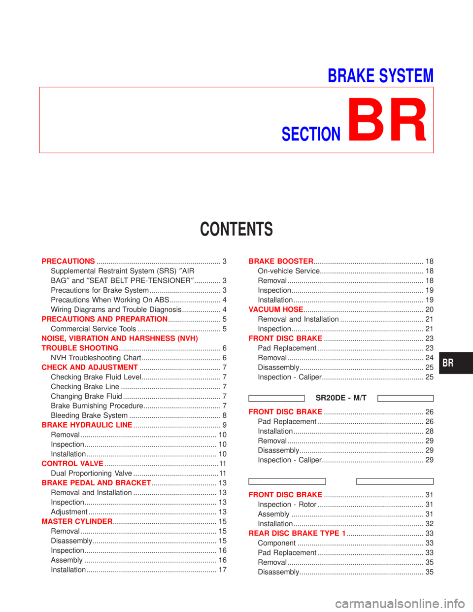
BRAKE SYSTEM
SECTION
BR
CONTENTS
PRECAUTIONS............................................................. 3
Supplemental Restraint System (SRS)²AIR
BAG²and²SEAT BELT PRE-TENSIONER²............. 3
Precautions for Brake System ................................... 3
Precautions When Working On ABS ......................... 4
Wiring Diagrams and Trouble Diagnosis ................... 4
PRECAUTIONS AND PREPARATION.......................... 5
Commercial Service Tools ......................................... 5
NOISE, VIBRATION AND HARSHNESS (NVH)
TROUBLE SHOOTING.................................................. 6
NVH Troubleshooting Chart....................................... 6
CHECK AND ADJUSTMENT........................................ 7
Checking Brake Fluid Level....................................... 7
Checking Brake Line ................................................. 7
Changing Brake Fluid ................................................ 7
Brake Burnishing Procedure...................................... 7
Bleeding Brake System ............................................. 8
BRAKE HYDRAULIC LINE........................................... 9
Removal ................................................................... 10
Inspection................................................................. 10
Installation ................................................................ 10
CONTROL VALVE........................................................ 11
Dual Proportioning Valve .......................................... 11
BRAKE PEDAL AND BRACKET................................ 13
Removal and Installation ......................................... 13
Inspection................................................................. 13
Adjustment ............................................................... 13
MASTER CYLINDER................................................... 15
Removal ................................................................... 15
Disassembly............................................................. 15
Inspection................................................................. 16
Assembly ................................................................. 16
Installation ................................................................ 17BRAKE BOOSTER...................................................... 18
On-vehicle Service................................................... 18
Removal ................................................................... 18
Inspection................................................................. 19
Installation ................................................................ 19
VACUUM HOSE........................................................... 20
Removal and Installation ......................................... 21
Inspection................................................................. 21
FRONT DISC BRAKE................................................. 23
Pad Replacement .................................................... 23
Removal ................................................................... 24
Disassembly............................................................. 25
Inspection - Caliper.................................................. 25
SR20DE - M/T
FRONT DISC BRAKE................................................. 26
Pad Replacement .................................................... 26
Installation ................................................................ 28
Removal ................................................................... 29
Disassembly............................................................. 29
Inspection - Caliper.................................................. 29
FRONT DISC BRAKE................................................. 31
Inspection - Rotor .................................................... 31
Assembly ................................................................. 31
Installation ................................................................ 32
REAR DISC BRAKE TYPE 1...................................... 33
Component .............................................................. 33
Pad Replacement .................................................... 33
Removal ................................................................... 35
Disassembly............................................................. 35
BR
Page 124 of 2267
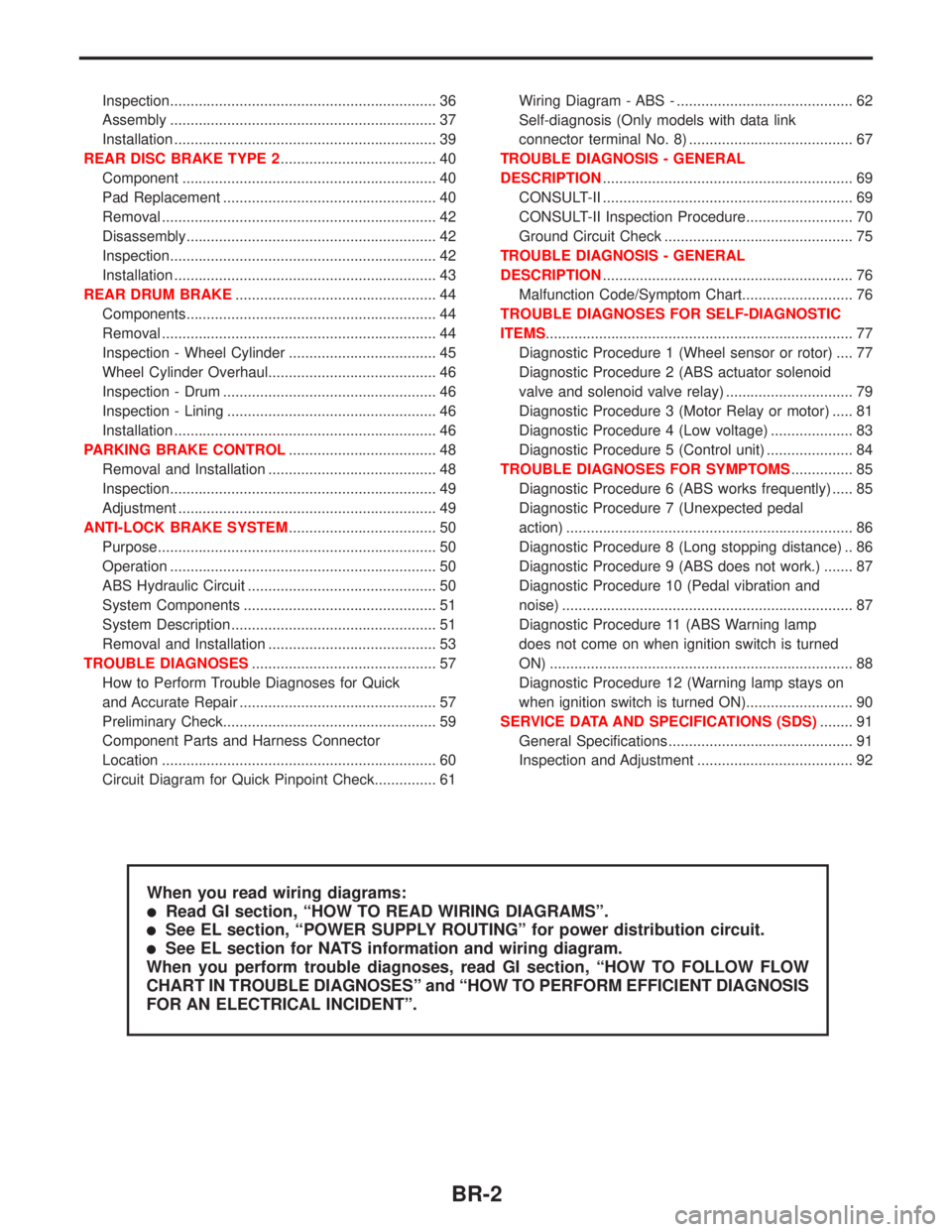
Inspection................................................................. 36
Assembly ................................................................. 37
Installation ................................................................ 39
REAR DISC BRAKE TYPE 2...................................... 40
Component .............................................................. 40
Pad Replacement .................................................... 40
Removal ................................................................... 42
Disassembly............................................................. 42
Inspection................................................................. 42
Installation ................................................................ 43
REAR DRUM BRAKE................................................. 44
Components............................................................. 44
Removal ................................................................... 44
Inspection - Wheel Cylinder .................................... 45
Wheel Cylinder Overhaul......................................... 46
Inspection - Drum .................................................... 46
Inspection - Lining ................................................... 46
Installation ................................................................ 46
PARKING BRAKE CONTROL.................................... 48
Removal and Installation ......................................... 48
Inspection................................................................. 49
Adjustment ............................................................... 49
ANTI-LOCK BRAKE SYSTEM.................................... 50
Purpose.................................................................... 50
Operation ................................................................. 50
ABS Hydraulic Circuit .............................................. 50
System Components ............................................... 51
System Description .................................................. 51
Removal and Installation ......................................... 53
TROUBLE DIAGNOSES............................................. 57
How to Perform Trouble Diagnoses for Quick
and Accurate Repair ................................................ 57
Preliminary Check.................................................... 59
Component Parts and Harness Connector
Location ................................................................... 60
Circuit Diagram for Quick Pinpoint Check............... 61Wiring Diagram - ABS - ........................................... 62
Self-diagnosis (Only models with data link
connector terminal No. 8) ........................................ 67
TROUBLE DIAGNOSIS - GENERAL
DESCRIPTION............................................................. 69
CONSULT-II ............................................................. 69
CONSULT-II Inspection Procedure.......................... 70
Ground Circuit Check .............................................. 75
TROUBLE DIAGNOSIS - GENERAL
DESCRIPTION............................................................. 76
Malfunction Code/Symptom Chart........................... 76
TROUBLE DIAGNOSES FOR SELF-DIAGNOSTIC
ITEMS........................................................................... 77
Diagnostic Procedure 1 (Wheel sensor or rotor) .... 77
Diagnostic Procedure 2 (ABS actuator solenoid
valve and solenoid valve relay) ............................... 79
Diagnostic Procedure 3 (Motor Relay or motor) ..... 81
Diagnostic Procedure 4 (Low voltage) .................... 83
Diagnostic Procedure 5 (Control unit) ..................... 84
TROUBLE DIAGNOSES FOR SYMPTOMS............... 85
Diagnostic Procedure 6 (ABS works frequently) ..... 85
Diagnostic Procedure 7 (Unexpected pedal
action) ...................................................................... 86
Diagnostic Procedure 8 (Long stopping distance) .. 86
Diagnostic Procedure 9 (ABS does not work.) ....... 87
Diagnostic Procedure 10 (Pedal vibration and
noise) ....................................................................... 87
Diagnostic Procedure 11 (ABS Warning lamp
does not come on when ignition switch is turned
ON) .......................................................................... 88
Diagnostic Procedure 12 (Warning lamp stays on
when ignition switch is turned ON).......................... 90
SERVICE DATA AND SPECIFICATIONS (SDS)........ 91
General Specifications ............................................. 91
Inspection and Adjustment ...................................... 92
When you read wiring diagrams:
lRead GI section, ªHOW TO READ WIRING DIAGRAMSº.
lSee EL section, ªPOWER SUPPLY ROUTINGº for power distribution circuit.
lSee EL section for NATS information and wiring diagram.
When you perform trouble diagnoses, read GI section, ªHOW TO FOLLOW FLOW
CHART IN TROUBLE DIAGNOSESº and ªHOW TO PERFORM EFFICIENT DIAGNOSIS
FOR AN ELECTRICAL INCIDENTº.
BR-2
Page 126 of 2267
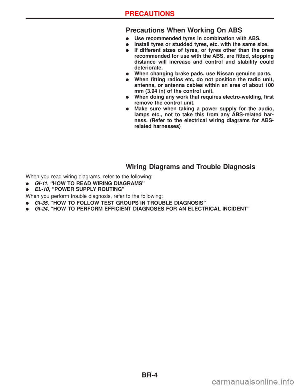
Precautions When Working On ABS
lUse recommended tyres in combination with ABS.
lInstall tyres or studded tyres, etc. with the same size.
lIf different sizes of tyres, or tyres other than the ones
recommended for use with the ABS, are fitted, stopping
distance will increase and control and stability could
deteriorate.
lWhen changing brake pads, use Nissan genuine parts.
lWhen fitting radios etc, do not position the radio unit,
antenna, or antenna cables within an area of about 100
mm (3.94 in) of the control unit.
lWhen doing any work that requires electro-welding, first
remove the control unit.
lMake sure when taking a power supply for the audio,
lamps etc., not to take this from any ABS-related har-
ness. (Refer to the electrical wiring diagrams for ABS-
related harnesses)
Wiring Diagrams and Trouble Diagnosis
When you read wiring diagrams, refer to the following:
lGI-11, ªHOW TO READ WIRING DIAGRAMSº
lEL-10, ªPOWER SUPPLY ROUTINGº
When you perform trouble diagnosis, refer to the following:
lGI-35, ªHOW TO FOLLOW TEST GROUPS IN TROUBLE DIAGNOSISº
lGI-24, ªHOW TO PERFORM EFFICIENT DIAGNOSES FOR AN ELECTRICAL INCIDENTº
PRECAUTIONS
BR-4
Page 130 of 2267
2. Use medium brake pedal/foot effort to bring the vehicle to a
complete stop from 50 km/h (31 MPH). Adjust brake pedal/
foot pressure such that vehicle stopping time equals 3 to 5
seconds.
3. To cool the brake system, drive the vehicle at 50 km/h (31
MPH) for 1 minute without stopping.
4. Repeat steps 1 to 3, 10 times or more to complete the bur-
nishing procedure.
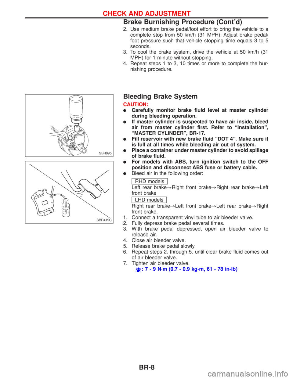
Bleeding Brake System
CAUTION:
lCarefully monitor brake fluid level at master cylinder
during bleeding operation.
lIf master cylinder is suspected to have air inside, bleed
air from master cylinder first. Refer to ªInstallationº,
ªMASTER CYLINDERº, BR-17.
lFill reservoir with new brake fluid ªDOT 4º. Make sure it
is full at all times while bleeding air out of system.
lPlace a container under master cylinder to avoid spillage
of brake fluid.
lFor models with ABS, turn ignition switch to the OFF
position and disconnect ABS fuse or battery cable.
lBleed air in the following order:
RHD models
Left rear brake,Right front brake,Right rear brake,Left
front brake
LHD models
Right rear brake,Left front brake,Left rear brake,Right
front brake.
1. Connect a transparent vinyl tube to air bleeder valve.
2. Fully depress brake pedal several times.
3. With brake pedal depressed, open air bleeder valve to
release air.
4. Close air bleeder valve.
5. Release brake pedal slowly.
6. Repeat steps 2. through 5. until clear brake fluid comes out
of air bleeder valve.
7. Tighten air bleeder valve.
:7-9N´m(0.7 - 0.9 kg-m, 61 - 78 in-lb)
SBR995
SBR419C
CHECK AND ADJUSTMENT
Brake Burnishing Procedure (Cont'd)
BR-8
Page 172 of 2267
Purpose
The Anti-Lock Brake System (ABS) consists of electronic and hydraulic components. It allows for control of
braking force so that locking of the wheels can be avoided.
The ABS:
1) Provides improved steering control during braking (by preventing front wheel lock).
2) Provides improved vehicle stability and skid prevention during braking (by avoiding rear wheel lock).
Operation
lWhen the vehicle speed is less than 10 km/h (6 mph) this system does not work.
lThe Anti-Lock Brake System (ABS) has self-test capabilities. The system turns on the ABS warning light
for 1 second after turning the ignition switch to the ªONº position. The system performs another test the
first time the vehicle reaches 6 km/h (4 mph). A mechanical noise may be heard as the ABS performs
a self-test. This is a normal part of the self-test feature. If a malfunction is found during this check, the
ABS warning light will come on.
lDuring ABS operation, a mechanical noise may be heard. This is a normal operating condition.
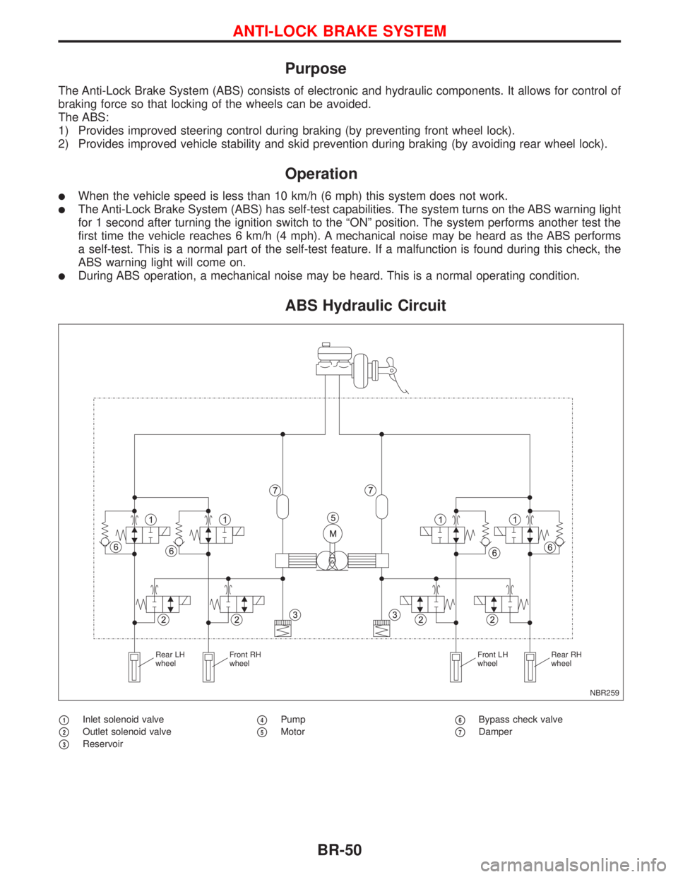
ABS Hydraulic Circuit
p1Inlet solenoid valve
p2Outlet solenoid valve
p3Reservoir
p4Pump
p5Motorp6Bypass check valve
p7Damper
NBR259 Rear LH
wheelFront RH
wheelFront LH
wheelRear RH
wheel
ANTI-LOCK BRAKE SYSTEM
BR-50