defogger NISSAN PRIMERA 1999 Electronic Repair Manual
[x] Cancel search | Manufacturer: NISSAN, Model Year: 1999, Model line: PRIMERA, Model: NISSAN PRIMERA 1999Pages: 2267, PDF Size: 35.74 MB
Page 331 of 2267
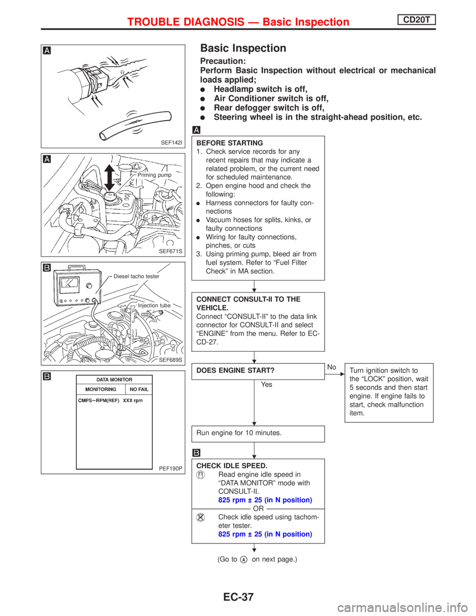
Basic Inspection
Precaution:
Perform Basic Inspection without electrical or mechanical
loads applied;
lHeadlamp switch is off,
lAir Conditioner switch is off,
lRear defogger switch is off,
lSteering wheel is in the straight-ahead position, etc.
BEFORE STARTING
1. Check service records for any
recent repairs that may indicate a
related problem, or the current need
for scheduled maintenance.
2. Open engine hood and check the
following:
lHarness connectors for faulty con-
nections
lVacuum hoses for splits, kinks, or
faulty connections
lWiring for faulty connections,
pinches, or cuts
3. Using priming pump, bleed air from
fuel system. Refer to ªFuel Filter
Checkº in MA section.
CONNECT CONSULT-II TO THE
VEHICLE.
Connect ªCONSULT-IIº to the data link
connector for CONSULT-II and select
ªENGINEº from the menu. Refer to EC-
CD-27.
DOES ENGINE START?
Ye s
ENo
Turn ignition switch to
the ªLOCKº position, wait
5 seconds and then start
engine. If engine fails to
start, check malfunction
item.
Run engine for 10 minutes.
CHECK IDLE SPEED.
Read engine idle speed in
ªDATA MONITORº mode with
CONSULT-II.
825 rpm 25 (in N position)
---------------------------------------------------------------------------------------------------------------------------------OR---------------------------------------------------------------------------------------------------------------------------------
Check idle speed using tachom-
eter tester.
825 rpm 25 (in N position)
(Go topAon next page.)
SEF142I
SEF671S
Priming pump
SEF689S
.Diesel tacho tester
.Injection tube
PEF190P
H
H
H
H
H
TROUBLE DIAGNOSIS Ð Basic InspectionCD20T
EC-37
Page 475 of 2267
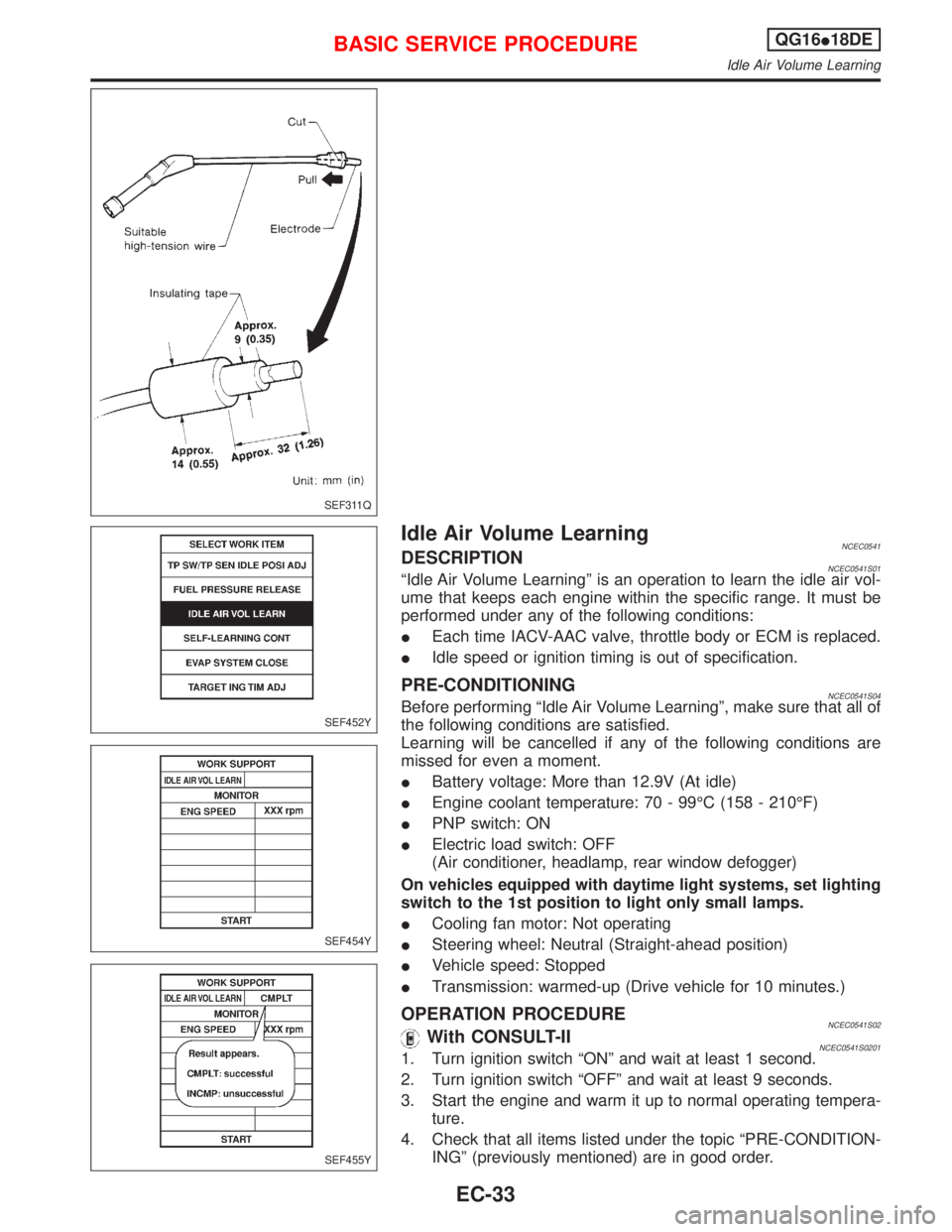
Idle Air Volume LearningNCEC0541DESCRIPTIONNCEC0541S01ªIdle Air Volume Learningº is an operation to learn the idle air vol-
ume that keeps each engine within the specific range. It must be
performed under any of the following conditions:
IEach time IACV-AAC valve, throttle body or ECM is replaced.
IIdle speed or ignition timing is out of specification.
PRE-CONDITIONINGNCEC0541S04Before performing ªIdle Air Volume Learningº, make sure that all of
the following conditions are satisfied.
Learning will be cancelled if any of the following conditions are
missed for even a moment.
IBattery voltage: More than 12.9V (At idle)
IEngine coolant temperature: 70 - 99ÉC (158 - 210ÉF)
IPNP switch: ON
IElectric load switch: OFF
(Air conditioner, headlamp, rear window defogger)
On vehicles equipped with daytime light systems, set lighting
switch to the 1st position to light only small lamps.
ICooling fan motor: Not operating
ISteering wheel: Neutral (Straight-ahead position)
IVehicle speed: Stopped
ITransmission: warmed-up (Drive vehicle for 10 minutes.)
OPERATION PROCEDURENCEC0541S02With CONSULT-IINCEC0541S02011. Turn ignition switch ªONº and wait at least 1 second.
2. Turn ignition switch ªOFFº and wait at least 9 seconds.
3. Start the engine and warm it up to normal operating tempera-
ture.
4. Check that all items listed under the topic ªPRE-CONDITION-
INGº (previously mentioned) are in good order.
SEF311Q
SEF452Y
SEF454Y
SEF455Y
BASIC SERVICE PROCEDUREQG16I18DE
Idle Air Volume Learning
EC-33
Page 502 of 2267
![NISSAN PRIMERA 1999 Electronic Repair Manual Monitored item [Unit]ECM
input
signalsMain
signalsDescription Remarks
AIR COND SIG
[ON/OFF]qqIIndicates [ON/OFF] condition of the air condi-
tioner switch as determined by the air condition-
ing signa](/img/5/57377/w960_57377-501.png "NISSAN PRIMERA 1999 Electronic Repair Manual Monitored item [Unit]ECM
input
signalsMain
signalsDescription Remarks
AIR COND SIG
[ON/OFF]qqIIndicates [ON/OFF] condition of the air condi-
tioner switch as determined by the air condition-
ing signa")
Monitored item [Unit]ECM
input
signalsMain
signalsDescription Remarks
AIR COND SIG
[ON/OFF]qqIIndicates [ON/OFF] condition of the air condi-
tioner switch as determined by the air condition-
ing signal.
P/N POSI SW
[ON/OFF]qqIIndicates [ON/OFF] condition from the PNP
switch signal.
PW/ST SIGNAL
[ON/OFF]qqIIndicates [ON/OFF] condition of the power steer-
ing oil pressure switch determined by the power
steering oil pressure switch signal.
LOAD SIGNAL
[ON/OFF]qqIIndicates [ON/OFF] condition from the electrical
load signal and/or lighting switch.
ON ... rear defogger is operating and/or lighting
switch is on.
OFF ... rear defogger is not operating and light-
ing switch is not on.
IGNITION SW
[ON/OFF]qIIndicates [ON/OFF] condition from ignition
switch.
HEATER FAN SW
[ON/OFF]qIIndicates [ON/OFF] condition from the heater
fan switch.
INJ PULSE-B1
[msec]qIIndicates the actual fuel injection pulse width
compensated by ECM according to the input
signals.IWhen the engine is stopped, a
certain computed value is indi-
cated.
B/FUEL SCHDL
[msec]IªBase fuel scheduleº indicates the fuel injection
pulse width programmed into ECM, prior to any
learned on board correction.
IGN TIMING [BTDC]qIIndicates the ignition timing computed by ECM
according to the input signals.
IACV-AAC/V [step]qIIndicates the IACV-AAC valve control value
computed by ECM according to the input sig-
nals.
A/F ALPHA-B1 [%]qIIndicates the mean value of the air-fuel ratio
feedback correction factor per cycle.IWhen the engine is stopped, a
certain value is indicated.
IThis data also includes the data
for the air-fuel ratio learning
control.
AIR COND RLY
[ON/OFF]qIIndicates the air conditioner relay control condi-
tion determined by ECM according to the input
signals.
FUEL PUMP RLY
[ON/OFF]qIIndicates the fuel pump relay control condition
determined by ECM according to the input sig-
nals.
INT/V SOL-B1
[ON/OFF]IThe control condition of the valve timing sole-
noid valve (determined by ECM according to the
input signal) is indicated.
ON ... Intake valve timing control operating
OFF ... Intake valve timing control not operating
COOLING FAN
[ON/OFF]qIIndicates the control condition of the cooling fan
determined by ECM according to the input sig-
nals.
HI ... High speed operation
LOW ... Low speed operation
OFF ... Stop
ON BOARD DIAGNOSTIC SYSTEM DESCRIPTIONQG16I18DE
CONSULT-II (Cont'd)
EC-60
Page 514 of 2267
Basic InspectionNCEC0038Precaution:
Perform Basic Inspection without electrical or mechanical
loads applied;
IHeadlamp switch is OFF,
On vehicle equipped with daytime light system, set lighting
switch to the 1st position to light only small lamps.
IAir conditioner switch is OFF,
IRear window defogger switch is OFF,
ISteering wheel is in the straight-ahead position, etc.
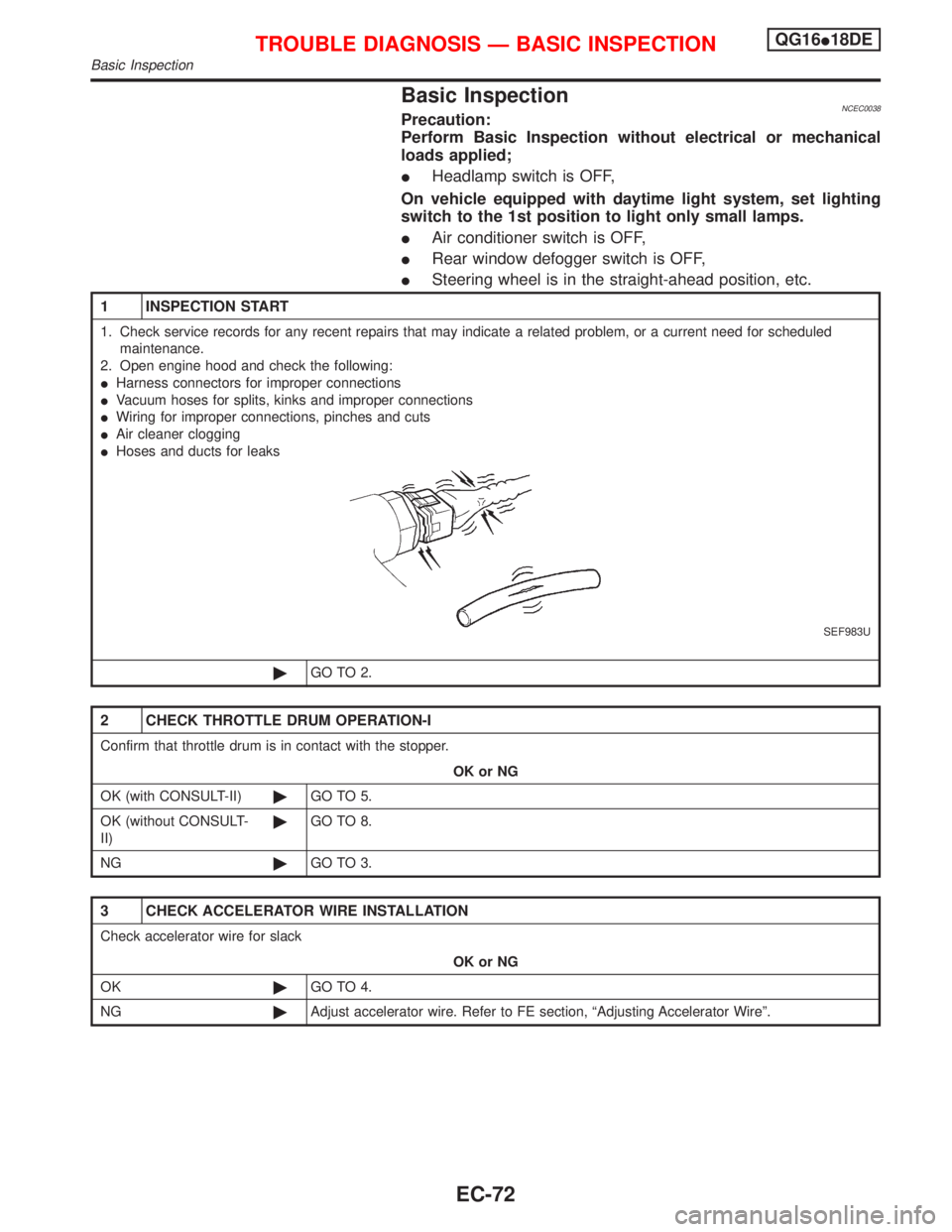
1 INSPECTION START
1. Check service records for any recent repairs that may indicate a related problem, or a current need for scheduled
maintenance.
2. Open engine hood and check the following:
IHarness connectors for improper connections
IVacuum hoses for splits, kinks and improper connections
IWiring for improper connections, pinches and cuts
IAir cleaner clogging
IHoses and ducts for leaks
SEF983U
©GO TO 2.
2 CHECK THROTTLE DRUM OPERATION-I
Confirm that throttle drum is in contact with the stopper.
OK or NG
OK (with CONSULT-II)©GO TO 5.
OK (without CONSULT-
II)©GO TO 8.
NG©GO TO 3.
3 CHECK ACCELERATOR WIRE INSTALLATION
Check accelerator wire for slack
OK or NG
OK©GO TO 4.
NG©Adjust accelerator wire. Refer to FE section, ªAdjusting Accelerator Wireº.
TROUBLE DIAGNOSIS Ð BASIC INSPECTIONQG16I18DE
Basic Inspection
EC-72
Page 529 of 2267
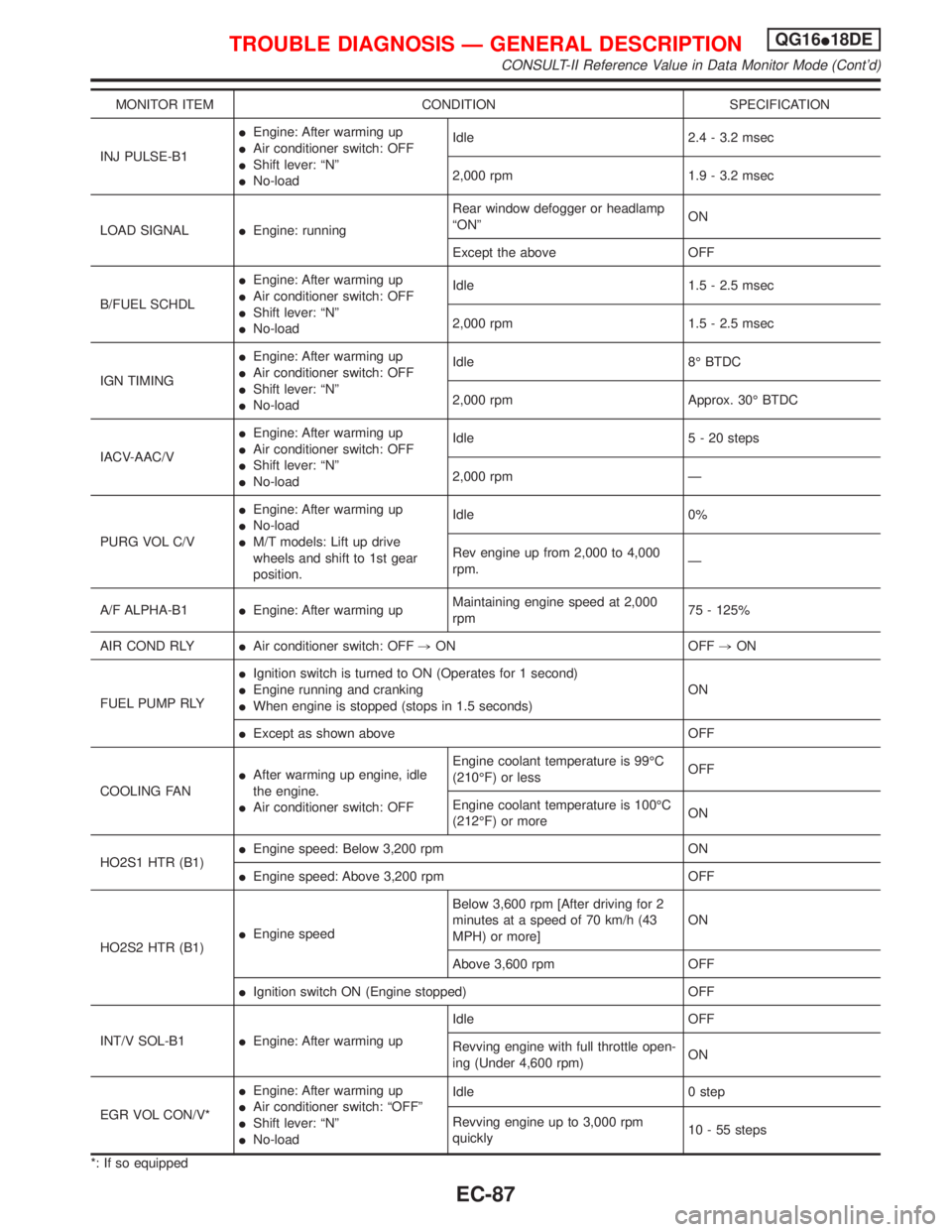
MONITOR ITEM CONDITION SPECIFICATION
INJ PULSE-B1IEngine: After warming up
IAir conditioner switch: OFF
IShift lever: ªNº
INo-loadIdle 2.4 - 3.2 msec
2,000 rpm 1.9 - 3.2 msec
LOAD SIGNALIEngine: runningRear window defogger or headlamp
ªONºON
Except the above OFF
B/FUEL SCHDLIEngine: After warming up
IAir conditioner switch: OFF
IShift lever: ªNº
INo-loadIdle 1.5 - 2.5 msec
2,000 rpm 1.5 - 2.5 msec
IGN TIMINGIEngine: After warming up
IAir conditioner switch: OFF
IShift lever: ªNº
INo-loadIdle 8É BTDC
2,000 rpm Approx. 30É BTDC
IACV-AAC/VIEngine: After warming up
IAir conditioner switch: OFF
IShift lever: ªNº
INo-loadIdle 5 - 20 steps
2,000 rpm Ð
PURG VOL C/VIEngine: After warming up
INo-load
IM/T models: Lift up drive
wheels and shift to 1st gear
position.Idle 0%
Rev engine up from 2,000 to 4,000
rpm.Ð
A/F ALPHA-B1IEngine: After warming upMaintaining engine speed at 2,000
rpm75 - 125%
AIR COND RLYIAir conditioner switch: OFF,ON OFF,ON
FUEL PUMP RLYIIgnition switch is turned to ON (Operates for 1 second)
IEngine running and cranking
IWhen engine is stopped (stops in 1.5 seconds)ON
IExcept as shown above OFF
COOLING FANIAfter warming up engine, idle
the engine.
IAir conditioner switch: OFFEngine coolant temperature is 99ÉC
(210ÉF) or lessOFF
Engine coolant temperature is 100ÉC
(212ÉF) or moreON
HO2S1 HTR (B1)IEngine speed: Below 3,200 rpm ON
IEngine speed: Above 3,200 rpm OFF
HO2S2 HTR (B1)IEngine speedBelow 3,600 rpm [After driving for 2
minutes at a speed of 70 km/h (43
MPH) or more]ON
Above 3,600 rpm OFF
IIgnition switch ON (Engine stopped) OFF
INT/V SOL-B1IEngine: After warming upIdle OFF
Revving engine with full throttle open-
ing (Under 4,600 rpm)ON
EGR VOL CON/V*IEngine: After warming up
IAir conditioner switch: ªOFFº
IShift lever: ªNº
INo-loadIdle 0 step
Revving engine up to 3,000 rpm
quickly10 - 55 steps
*: If so equipped
TROUBLE DIAGNOSIS Ð GENERAL DESCRIPTIONQG16I18DE
CONSULT-II Reference Value in Data Monitor Mode (Cont'd)
EC-87
Page 536 of 2267
![NISSAN PRIMERA 1999 Electronic Repair Manual TER-
MINAL
NO.WIRE
COLORITEM CONDITION DATA (DC Voltage)
44 GY Air conditioner switch[Engine is running]
IBoth air conditioner switch and blower switch
are ªONº (Compressor operates)Approximately 0V](/img/5/57377/w960_57377-535.png "NISSAN PRIMERA 1999 Electronic Repair Manual TER-
MINAL
NO.WIRE
COLORITEM CONDITION DATA (DC Voltage)
44 GY Air conditioner switch[Engine is running]
IBoth air conditioner switch and blower switch
are ªONº (Compressor operates)Approximately 0V")
TER-
MINAL
NO.WIRE
COLORITEM CONDITION DATA (DC Voltage)
44 GY Air conditioner switch[Engine is running]
IBoth air conditioner switch and blower switch
are ªONº (Compressor operates)Approximately 0V
[Engine is running]
IAir conditioner switch is ªOFFºApproximately 5V
46 PU/WPower steering oil pres-
sure switch[Engine is running]
ISteering wheel is fully turnedApproximately 0V
[Engine is running]
ISteering wheel is not turnedApproximately 5V
48 B ECM ground[Engine is running]
IIdle speedEngine ground
50 RElectrical load signal
(Headlamp
Rear defogger)[Engine is running]
IHeadlamp switch or rear defogger switch is
ªONºBATTERY VOLTAGE
(11 - 14V)
[Engine is running]
IHeadlamp switch and rear defogger switch are
ªOFFºApproximately 0V
51 LG/B Blower fan SW[Ignition switch ªONº]
IBlower fan switch is ªONºApproximately 0V
57 B ECM ground[Engine is running]
IIdle speedEngine ground
58 B Sensors' ground[Engine is running]
IWarm-up condition
IIdle speedApproximately 0V
61 B Mass air flow sensor[Engine is running]
IWarm-up condition
IIdle speed1.0 - 1.7V
[Engine is running]
IWarm-up condition
IEngine speed is 2,500 rpm1.5 - 2.1V
62 RHeated oxygen sensor
1 (front)[Engine is running]
IWarm-up condition
IEngine speed is 2,000 rpm0 - Approximately 0.7V
SEF008W
63 LHeated oxygen sensor
2 (rear)[Engine is running]
IAfter warming up to normal operating tempera-
ture and engine speed is 3,000 rpm0 - Approximately 1.0V
64 GIntake air temperature
sensor[Engine is running]Approximately 0 - 4.8V
Output voltage varies with
intake air temperature
TROUBLE DIAGNOSIS Ð GENERAL DESCRIPTIONQG16I18DE
ECM Terminals and Reference Value (Cont'd)
EC-94
Page 540 of 2267
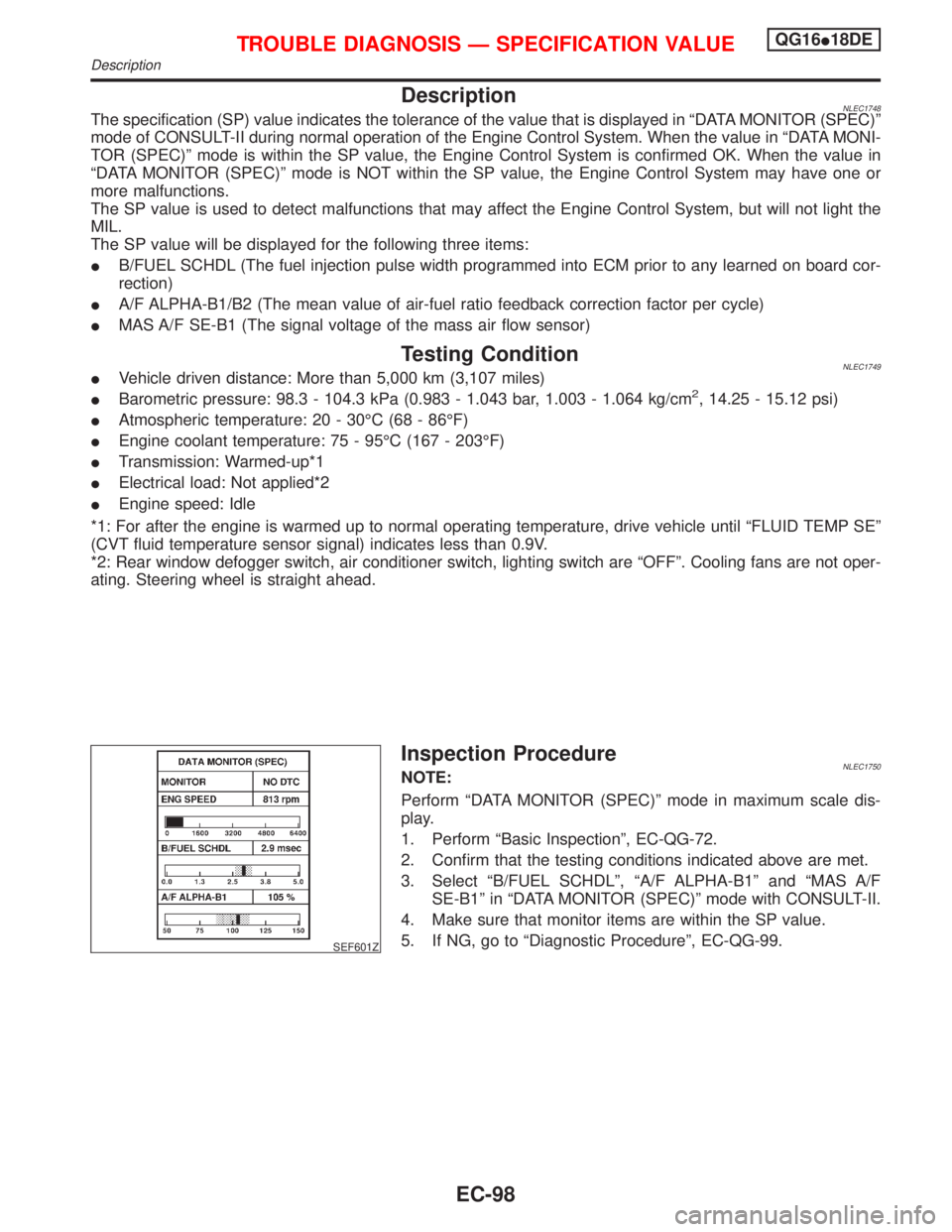
DescriptionNLEC1748The specification (SP) value indicates the tolerance of the value that is displayed in ªDATA MONITOR (SPEC)º
mode of CONSULT-II during normal operation of the Engine Control System. When the value in ªDATA MONI-
TOR (SPEC)º mode is within the SP value, the Engine Control System is confirmed OK. When the value in
ªDATA MONITOR (SPEC)º mode is NOT within the SP value, the Engine Control System may have one or
more malfunctions.
The SP value is used to detect malfunctions that may affect the Engine Control System, but will not light the
MIL.
The SP value will be displayed for the following three items:
IB/FUEL SCHDL (The fuel injection pulse width programmed into ECM prior to any learned on board cor-
rection)
IA/F ALPHA-B1/B2 (The mean value of air-fuel ratio feedback correction factor per cycle)
IMAS A/F SE-B1 (The signal voltage of the mass air flow sensor)
Testing ConditionNLEC1749IVehicle driven distance: More than 5,000 km (3,107 miles)
IBarometric pressure: 98.3 - 104.3 kPa (0.983 - 1.043 bar, 1.003 - 1.064 kg/cm2, 14.25 - 15.12 psi)
IAtmospheric temperature: 20 - 30ÉC (68 - 86ÉF)
IEngine coolant temperature: 75 - 95ÉC (167 - 203ÉF)
ITransmission: Warmed-up*1
IElectrical load: Not applied*2
IEngine speed: Idle
*1: For after the engine is warmed up to normal operating temperature, drive vehicle until ªFLUID TEMP SEº
(CVT fluid temperature sensor signal) indicates less than 0.9V.
*2: Rear window defogger switch, air conditioner switch, lighting switch are ªOFFº. Cooling fans are not oper-
ating. Steering wheel is straight ahead.
SEF601Z
Inspection ProcedureNLEC1750NOTE:
Perform ªDATA MONITOR (SPEC)º mode in maximum scale dis-
play.
1. Perform ªBasic Inspectionº, EC-QG-72.
2. Confirm that the testing conditions indicated above are met.
3. Select ªB/FUEL SCHDLº, ªA/F ALPHA-B1º and ªMAS A/F
SE-B1º in ªDATA MONITOR (SPEC)º mode with CONSULT-II.
4. Make sure that monitor items are within the SP value.
5. If NG, go to ªDiagnostic Procedureº, EC-QG-99.
TROUBLE DIAGNOSIS Ð SPECIFICATION VALUEQG16I18DE
Description
EC-98
Page 793 of 2267
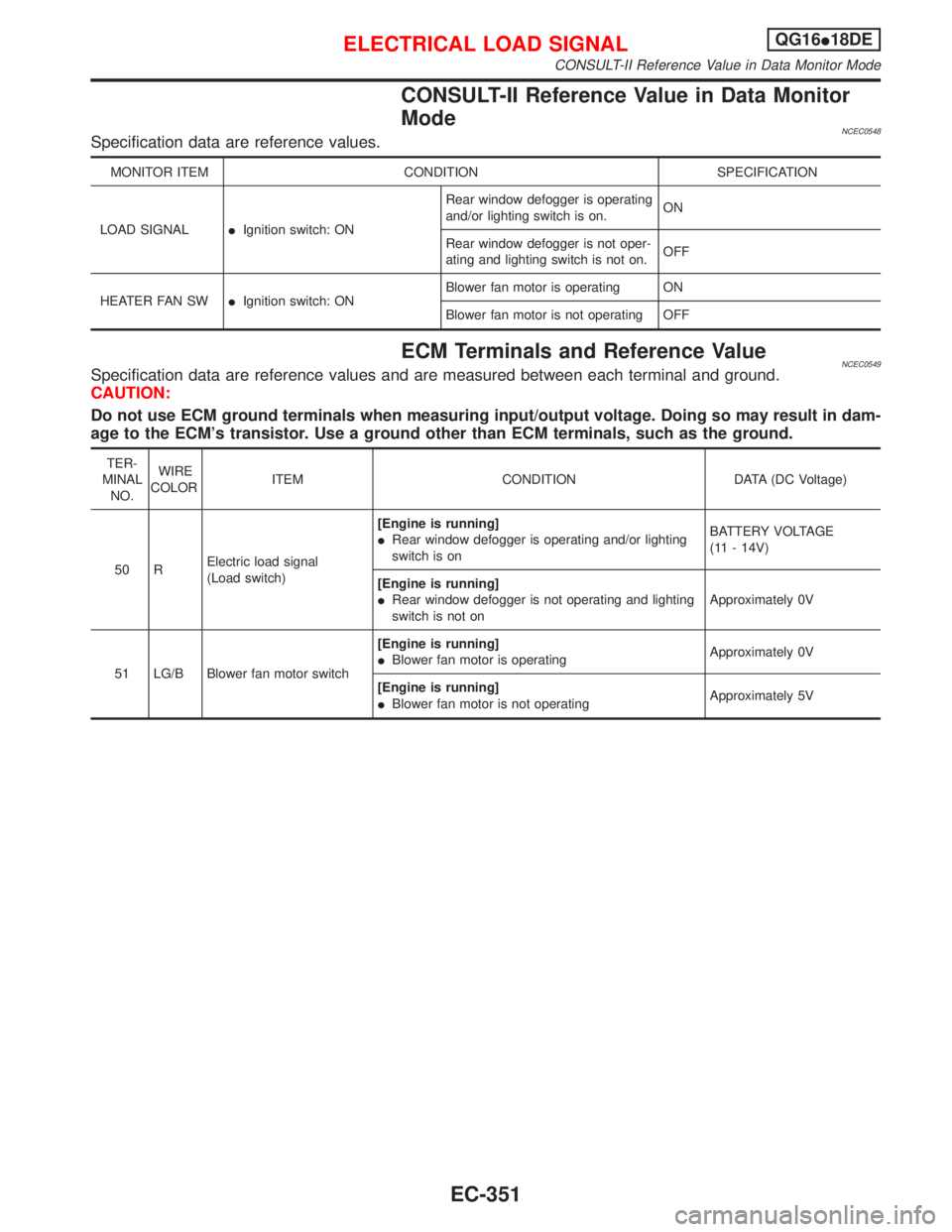
CONSULT-II Reference Value in Data Monitor
Mode
NCEC0548Specification data are reference values.
MONITOR ITEM CONDITION SPECIFICATION
LOAD SIGNALIIgnition switch: ONRear window defogger is operating
and/or lighting switch is on.ON
Rear window defogger is not oper-
ating and lighting switch is not on.OFF
HEATER FAN SWIIgnition switch: ONBlower fan motor is operating ON
Blower fan motor is not operating OFF
ECM Terminals and Reference ValueNCEC0549Specification data are reference values and are measured between each terminal and ground.
CAUTION:
Do not use ECM ground terminals when measuring input/output voltage. Doing so may result in dam-
age to the ECM's transistor. Use a ground other than ECM terminals, such as the ground.
TER-
MINAL
NO.WIRE
COLORITEM CONDITION DATA (DC Voltage)
50 RElectric load signal
(Load switch)[Engine is running]
IRear window defogger is operating and/or lighting
switch is onBATTERY VOLTAGE
(11 - 14V)
[Engine is running]
IRear window defogger is not operating and lighting
switch is not onApproximately 0V
51 LG/B Blower fan motor switch[Engine is running]
IBlower fan motor is operatingApproximately 0V
[Engine is running]
IBlower fan motor is not operatingApproximately 5V
ELECTRICAL LOAD SIGNALQG16I18DE
CONSULT-II Reference Value in Data Monitor Mode
EC-351
Page 797 of 2267
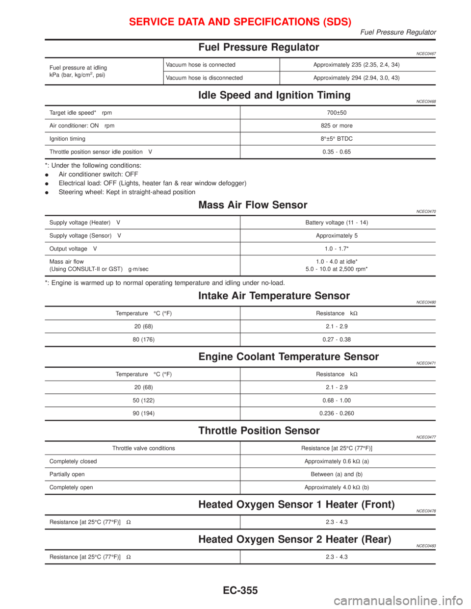
Fuel Pressure RegulatorNCEC0467
Fuel pressure at idling
kPa (bar, kg/cm2, psi)Vacuum hose is connected Approximately 235 (2.35, 2.4, 34)
Vacuum hose is disconnected Approximately 294 (2.94, 3.0, 43)
Idle Speed and Ignition TimingNCEC0468
Target idle speed* rpm700 50
Air conditioner: ON rpm825 or more
Ignition timing8É 5É BTDC
Throttle position sensor idle position V 0.35 - 0.65
*: Under the following conditions:
IAir conditioner switch: OFF
IElectrical load: OFF (Lights, heater fan & rear window defogger)
ISteering wheel: Kept in straight-ahead position
Mass Air Flow SensorNCEC0470
Supply voltage (Heater) VBattery voltage (11 - 14)
Supply voltage (Sensor) VApproximately 5
Output voltage V1.0 - 1.7*
Mass air flow
(Using CONSULT-II or GST) g×m/sec1.0 - 4.0 at idle*
5.0 - 10.0 at 2,500 rpm*
*: Engine is warmed up to normal operating temperature and idling under no-load.
Intake Air Temperature SensorNCEC0480
Temperature ÉC (ÉF) Resistance kW
20 (68) 2.1 - 2.9
80 (176) 0.27 - 0.38
Engine Coolant Temperature SensorNCEC0471
Temperature ÉC (ÉF) Resistance kW
20 (68) 2.1 - 2.9
50 (122) 0.68 - 1.00
90 (194) 0.236 - 0.260
Throttle Position SensorNCEC0477
Throttle valve conditions Resistance [at 25ÉC (77ÉF)]
Completely closedApproximately 0.6 kW(a)
Partially openBetween (a) and (b)
Completely openApproximately 4.0 kW(b)
Heated Oxygen Sensor 1 Heater (Front)NCEC0478
Resistance [at 25ÉC (77ÉF)]W2.3 - 4.3
Heated Oxygen Sensor 2 Heater (Rear)NCEC0483
Resistance [at 25ÉC (77ÉF)]W2.3 - 4.3
SERVICE DATA AND SPECIFICATIONS (SDS)
Fuel Pressure Regulator
EC-355
Page 834 of 2267
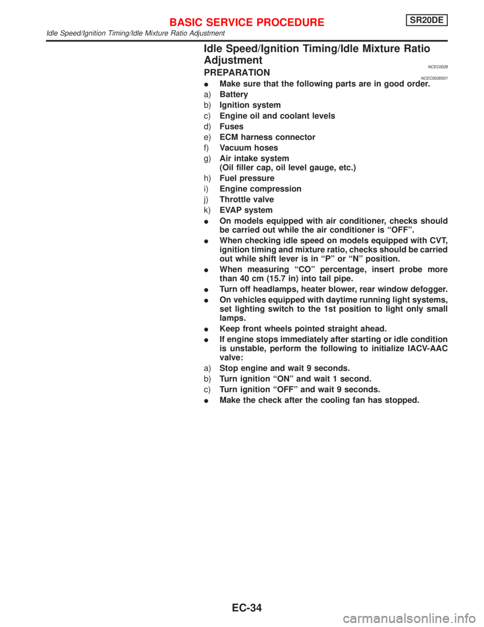
Idle Speed/Ignition Timing/Idle Mixture Ratio
Adjustment
NCEC0028PREPARATIONNCEC0028S01IMake sure that the following parts are in good order.
a)Battery
b)Ignition system
c)Engine oil and coolant levels
d)Fuses
e)ECM harness connector
f)Vacuum hoses
g)Air intake system
(Oil filler cap, oil level gauge, etc.)
h)Fuel pressure
i)Engine compression
j)Throttle valve
k)EVAP system
IOn models equipped with air conditioner, checks should
be carried out while the air conditioner is ªOFFº.
IWhen checking idle speed on models equipped with CVT,
ignition timing and mixture ratio, checks should be carried
out while shift lever is in ªPº or ªNº position.
IWhen measuring ªCOº percentage, insert probe more
than 40 cm (15.7 in) into tail pipe.
ITurn off headlamps, heater blower, rear window defogger.
IOn vehicles equipped with daytime running light systems,
set lighting switch to the 1st position to light only small
lamps.
IKeep front wheels pointed straight ahead.
IIf engine stops immediately after starting or idle condition
is unstable, perform the following to initialize IACV-AAC
valve:
a)Stop engine and wait 9 seconds.
b)Turn ignition ªONº and wait 1 second.
c)Turn ignition ªOFFº and wait 9 seconds.
IMake the check after the cooling fan has stopped.
BASIC SERVICE PROCEDURESR20DE
Idle Speed/Ignition Timing/Idle Mixture Ratio Adjustment
EC-34