engine NISSAN PULSAR 1987 Workshop Manual
[x] Cancel search | Manufacturer: NISSAN, Model Year: 1987, Model line: PULSAR, Model: NISSAN PULSAR 1987Pages: 238, PDF Size: 28.91 MB
Page 216 of 238

216 Electrical System
NOTE: While checking the operation of the
fusible link, loosely connect the battery-
terminal only, to safeguard against damage
to the wiring harness.
(5) If the circuit is still inoperative or the fusible
link burns out again, refer the problem to an auto-
motive electrician.
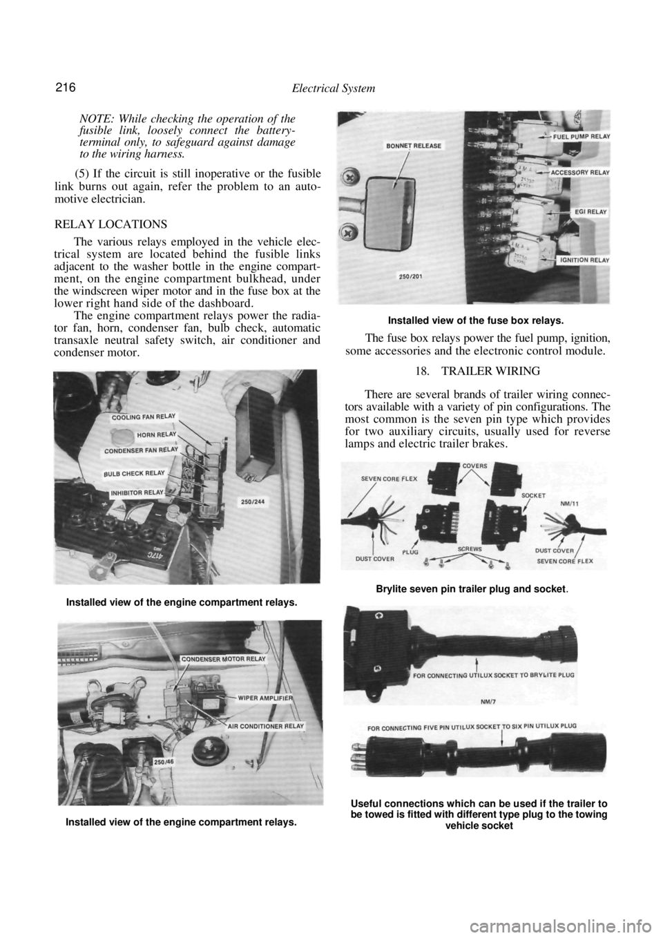
RELAY LOCATIONS
The various relays employed in the vehicle elec-
trical system are located behind the fusible links
adjacent to the washer bottle in the engine compart-
ment, on the engine compartment bulkhead, under
the windscreen wiper motor and in the fuse box at the
lower right hand side of the dashboard.
The engine compartment relays power the radia-
tor fan, horn, condenser fan, bulb check, automatic
transaxle neutral safety switch, air conditioner and
condenser motor.
Installed view of the fuse box relays.
The fuse box relays power the fuel pump, ignition,
some accessories and the el ectronic control module.
18. TRAILER WIRING
There are several brands of trailer wiring connec-
tors available with a variet y of pin configurations. The
most common is the seven pin type which provides
for two auxiliary circuits, usually used for reverse
lamps and electric trailer brakes.
Installed view of the engine compartment relays.
Installed view of the engine compartment relays.
Useful connections which can be used if the trailer to
be towed is fitted with different type plug to the towing
vehicle socket
Brylite seven pin trailer plug and socket.
Page 219 of 238

Electrical System 219
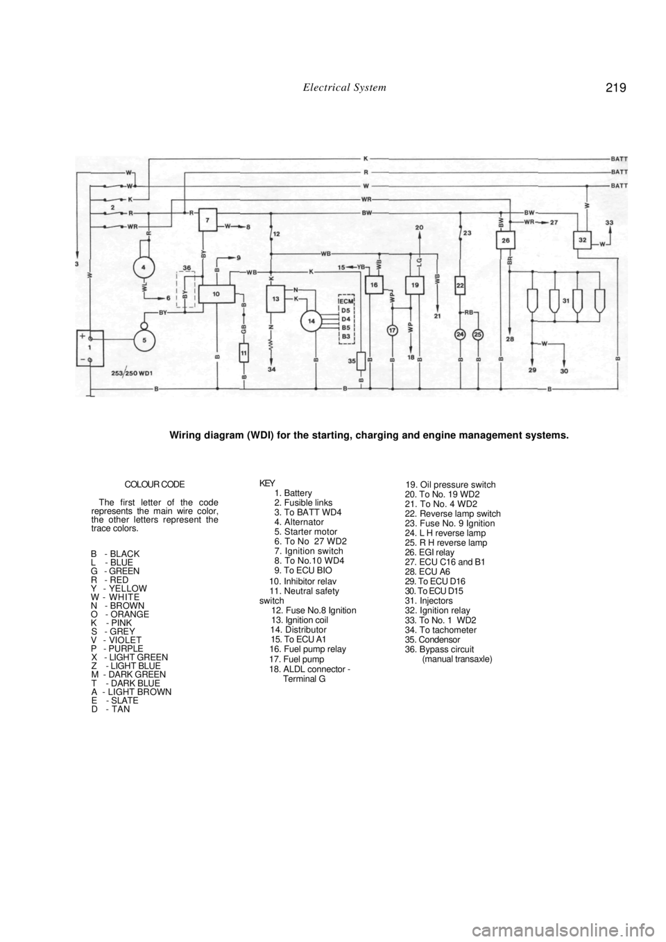
Wiring diagram (WDI) for the starting, charging and engine management systems.
COLOUR CODE
The first letter of the code
represents the main wire color,
the other letters represent the
trace colors.
B - BLACK
L - BLUE
G - GREEN
R - RED
Y - YELLOW
W - WHITE
N - BROWN
O - ORANGE
K - PINK
S - GREY V - VIOLET
P - PURPLE X - LIGHT GREEN
Z - LIGHT BLUE
M - DARK GREEN
T - DARK BLUE
A - LIGHT BROWN
E - SLATE
D - TAN
KEY 1. Battery
2. Fusible links
3. To BATT WD4
4. Alternator
5. Starter motor
6. To No 27 WD2
7. Ignition switch
8. To No.10 WD4
9. To ECU BIO
10. Inhibitor relav
11. Neutral safety
switch
12. Fuse No.8 Ignition
13. Ignition coil
14. Distributor
15. To ECU A1
16. Fuel pump relay
17. Fuel pump
18. ALDL connector - Terminal G
19. Oil pressure switch
20. To No. 19 WD2
21. To No. 4 WD2
22. Reverse lamp switch
23. Fuse No. 9 Ignition
24. L H reverse lamp
25. R H reverse lamp
26. EGI relay
27. ECU C16 and B1
28. ECU A6
29. To ECU D16
30. To ECU D15
31. Injectors
32. Ignition relay
33. To No. 1 WD2
34. To tachometer
35. Condensor
36. Bypass circuit (manual transaxle)
Page 231 of 238

Body 231
4. ENGINE BONNET
TO REMOVE, INSTAL AND ADJUST
Raise the engine bonnet and place covers on
both front mudguards. Mark the hinge mountings on
the bonnet with a soft lead pencil to aid assembly.
Place a quantity of soft rag folded several
times under each rear corner of the bonnet on the
scuttle panel. Disconnect the windscreen washer hose from
the bonnet at the tee piece. With the aid of an assistant supporting the
bonnet, remove the retaining bolts and lift the bonnet
from the vehicle. Installation is a reversal of the removal procedure
with attention to the following points:
Holding the bonnet in the position previ-
ously marked, install the bonnet hinge bolts
and
tighten to just over finger tight.
Close the bonnet and by pushing with the
hand, position the bonnet evenly in its opening.
Open the bonnet carefully and tighten the
mounting bolts. Check for correct positioning and adjust
again if necessary. Check the adjustment of the bonnet catch.
When the bonnet is closed the bonnet should align
with the front panels. When the catch is released the
bonnet should pop up sufficiently to enable the safety
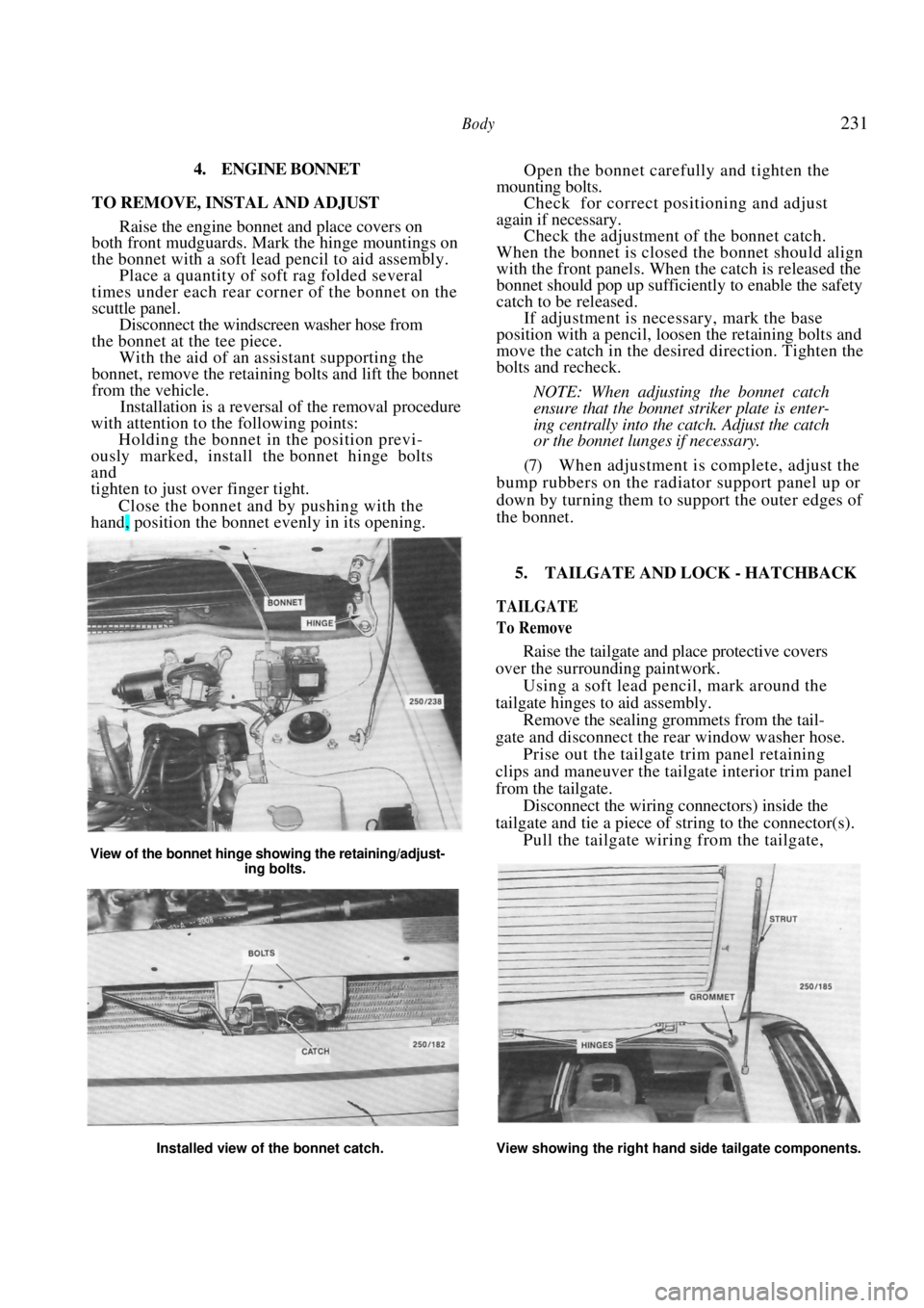
catch to be released. If adjustment is necessary, mark the base
position with a pencil, loosen the retaining bolts and
move the catch in the desired direction. Tighten the
bolts and recheck.
NOTE: When adjusting the bonnet catch
ensure that the bonnet striker plate is enter-
ing centrally into the catch. Adjust the catch
or the bonnet lunges if necessary.
(7) When adjustment is complete, adjust the
bump rubbers on the radiator support panel up or
down by turning them to support the outer edges of
the bonnet.
View of the bonnet hinge showing the retaining/adjust-
ing bolts.
5. TAILGATE AND LOCK - HATCHBACK
TAILGATE
To Remove
Raise the tailgate and place protective covers
over the surrounding paintwork.
Using a soft lead pencil, mark around the
tailgate hinges to aid assembly. Remove the sealing grommets from the tail-
gate and disconnect the rear window washer hose. Prise out the tailgate trim panel retaining
clips and maneuver the tailgate interior trim panel
from the tailgate.
Disconnect the wiring connectors) inside the
tailgate and tie a piece of st ring to the connector(s).
Pull the tailgate wiring from the tailgate,
Installed view of the bonnet catch. View showing the right hand side tailgate components.