battery replacement NISSAN PULSAR 1987 Workshop Manual
[x] Cancel search | Manufacturer: NISSAN, Model Year: 1987, Model line: PULSAR, Model: NISSAN PULSAR 1987Pages: 238, PDF Size: 28.91 MB
Page 89 of 238

Fuel and Engine Management 89
The procedure for fabricating an LED test lamp is
fully described in the El ectrical System section.
If a conventional test lamp with a filament type
bulb is to be used, ensure that the current draw of the
test lamp does not exceed 0.3 amp to avoid damage to
the electronic components.
To check the current draw connect an accurate
ammeter, such as the multimeter described previ-
ously, in series with the test lamp and a battery.
If the ammeter reads less than 0.3 amp the test
lamp is suitable.
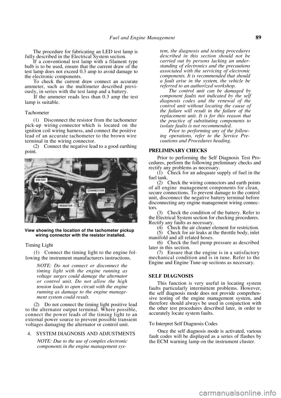
Tachometer
(1) Disconnect the resistor from the tachometer
pick-up wiring connector which is located on the
ignition coil wiring harness, and connect the positive
lead of an accurate tachometer to the brown wire
terminal in the wiring connector. (2) Connect the negative lead to a good earthing
point.
View showing the location of the tachometer pickup
wiring connector with the resistor installed.
Timing Light
(1) Connect the timing light to the engine fol-
lowing the instrument manufacturers instructions.
NOTE: Do not connect or disconnect the
timing light with the engine running as
voltage surges could damage the alternator
or control unit. Do not allow the high
tension leads to open circuit with the engine
running as damage to the engine manage-
ment system could result.
(2) Do not connect the timing light positive lead
to the alternator output terminal. Where possible,
connect the power leads of the timing light to an
external power source to prevent possible transient
voltages damaging the alternator or control unit.
4. SYSTEM DIAGNOSIS AND ADJUSTMENTS
NOTE: Due to the use of complex electronic
components in the engine management sys-
tem, the diagnosis and testing procedures
described in this section should not be
carried out by persons lacking an under-
standing of electronics and the precautions
associated with the servicing of electronic
components. It is rec ommended that should
a fault arise in the system, the vehicle be
referred to an authorized workshop.
The control unit can be damaged by
component faults not indicated by the self
diagnosis codes and the renewal of the
control unit without lo cating the cause of
the failure will result in the failure of the
replacement unit. It is for this reason that
the practice of substituting components to
isolate faults is not recommended.
Prior to performing any of the follow-
ing operations, refer to the Service Pre-
cautions and Procedures heading.
PRELIMINARY CHECKS
Prior to performing the Self Diagnosis Test Pro-
cedures, perform the following preliminary checks and
rectify any problems as necessary.
(1) Check for an adequate supply of fuel in the
fuel tank. (2) Check the wiring connectors and earth points
of all engine management components for clean,
secure connections. To prevent damage to the control
unit, disconnect the negative battery terminal before
disconnecting any engine ma nagement wiring connec-
tors. (3) Check the condition of the battery. Refer to
the Electrical System sectio n for checking procedures.
Rectify any faults as necessary. (4) Check the air cleaner element for restriction.
(5) Check for air leaks at the throttle body, inlet
manifold and all related hoses. (6) Check the fuel pump pr essure as described
later in this section. (7) Ensure that the engine is in a satisfactory
mechanical condition and is in tune. Refer to the
Engine and Engine Tune-up sections as necessary.
SELF DIAGNOSIS
This function is very useful in locating system
faults particularly intermittent problems. However,
the self diagnosis mode does not provide comprehen-
sive testing of the engine management system, and
therefore should always be used in conjunction with
the other test procedures described later, in order to
accurately locate system faults.
To Interpret Self Diagnosis Codes
Once the self diagnosis mode is activated, various
fault codes will be displayed as a series of flashes by
the ECM warning lamp on the instrument cluster.
Page 193 of 238

Electrical System 193
Installed view of the stop lamp switch and the flasher
unit.
(2) Fault in the warning lamp wiring: Check and
repair the fault.
NOTE: When renewing bulbs ensure that a
new bulb of the correct wattage is used.
TURN SIGNAL LAMPS FLASH WEAKLY AND
AT GREATER THAN NORMAL SPEED
1. Faulty flasher unit: Check and renew the
flasher unit.
2. Front or rear bulb blown on the turn side:
Check and renew the bulb.
NOTE: If the flasher unit is to be renewed,
always try to obtain a genuine replacement
part.
HAZARD WARNING LAMPS DO NOT
OPERATE
Fuse blown: Rectify the fault and renew as
necessary.
Flasher unit faulty: Re new the flasher unit.
Hazard warning switch faulty: Renew the
switch.
Fault in the wiring circuit: Check and repair
the fault.
5. TEST EQUIPMENT AND SOME APPLICATIONS
Special Equipment Required:
To Make Test Lamp or Jumper Lead — Soldering
iron
When working on the electrical system, a test
lamp and jumper leads can be very useful to check
circuits.
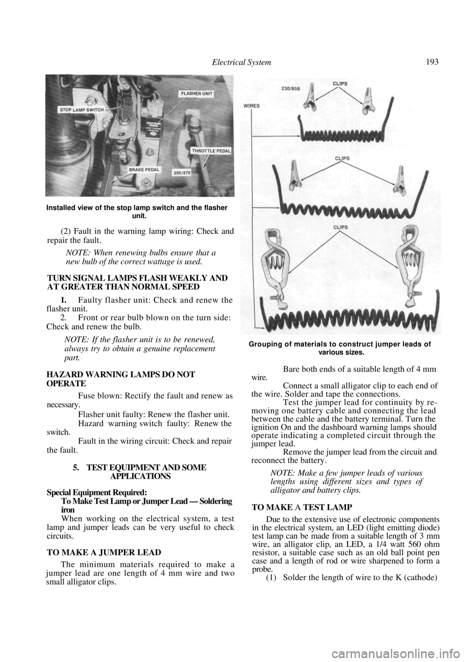
TO MAKE A JUMPER LEAD
The minimum materials required to make a
jumper lead are one length of 4 mm wire and two
small alligator clips.
Grouping of materials to construct jumper leads of
various sizes.
Bare both ends of a suitable length of 4 mm
wire. Connect a small alligato r clip to each end of
the wire. Solder and tape the connections. Test the jumper lead for continuity by re-
moving one battery cable and connecting the lead
between the cable and the battery terminal. Turn the
ignition On and the dashboard warning lamps should
operate indicating a completed circuit through the
jumper lead. Remove the jumper lead from the circuit and
reconnect the battery.
NOTE: Make a few jumper leads of various
lengths using different sizes and types of
alligator and battery clips.
TO MAKE A TEST LAMP
Due to the extensive use of electronic components
in the electrical system, an LED (light emitting diode)
test lamp can be made from a suitable length of 3 mm
wire, an alligator clip, an LED, a 1/4 watt 560 ohm
resistor, a suitable case such as an old ball point pen
case and a length of rod or wire sharpened to form a
probe.
(1) Solder the length of wire to the K (cathode)
Page 197 of 238

Electrical System 197
Switch on all lamps and allow them to
illuminate for approximately five minutes to reduce
the charge of the battery and to apply a load to the
circuit.
Start the engine and gradually increase the
speed to approximately 2 500 rpm. The reading on
the ammeter should be approximately 75% of the
rated output of the altern ator. See Specifications.
Switch off all the lamps and run the engine at
1 500-2 000 rpm until the indicated charge is below
10 amps. The voltmeter should now read in excess of
13.6 volts.
NOTE: Should the alternator fail to reach
the specific output, the unit will have to be
removed and overhauled or a replacement
unit installed.
Should the voltage reading be above or
below Specifications, the regulator will have
to be renewed.
TO REMOVE AND INSTAL
Disconnect the negative battery terminal.
On 1.8 liter engines, remove the bolt secur-
ing the air cleaner intake duct and remove the air
cleaner intake duct. Drain the radiator by releasing the radiator
drain plug, located at the bottom of the radiator and
allow the coolant level to fall below the thermostat
housing level. NOTE: Refer to the Cooling and Heating
Systems section when refilling the radiator
coolant to its correct l
evel, failure to do so
could result in severe damage to engine
components.
Remove the retaining bolts securing the
thermostat housing, disconnect the hose from the
radiator and remove the thermostat housing and
radiator hose from the vehicle. Using a socket and extension bar, remove the
bolt securing the alternator to the drive belt tensioning
bar located under the alternator. On vehicles not equipped with air condition-
ing, remove the front splash guard from under the
front of the vehicle and remove the bolt securing the
alternator to the drive belt tensioning bar. Loosen the upper mounting bolts, slacken
the alternator drive belt and remove it from the
alternator pulley.
While supporting the alternator, remove the
upper mounting bolts and remove the alternator from
the vehicle. Installation is a reversal of the removal procedure
with attention to the following points:
Do not over tension the drive belt. Refer
to
the Engine Tune-up section for the correct belt
adjusting procedure. Ensure that the wiring and connectors are
securely located on the alternator.
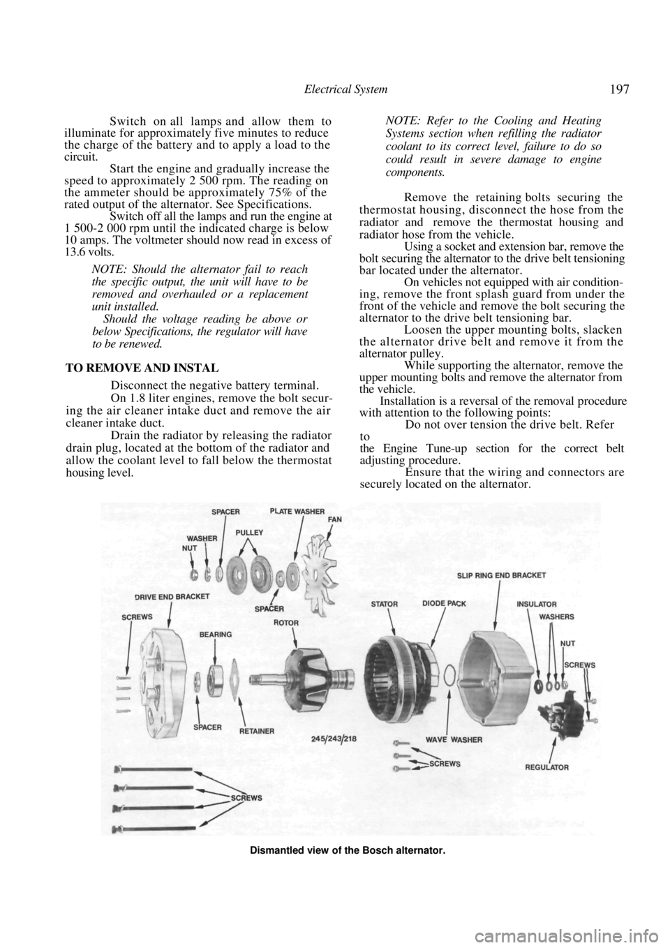
Dismantled view of the Bosch alternator.
Page 215 of 238

Electrical System 215
Ensure that the wiper motor is in the Park
position before installing the wiper arm. If in doubt,
turn the wiper switch to the Off position and turn the
ignition switch to the On position until the wiper
motor stops.
Install the wiper arm to the pivot so that the
wiper blade is horizontal to the lower edge of the edge
of the rear window when in the Park position.
17. FUSES, FUSIBLE LINKS AND RELAYS
TO CHECK AND RENEW FUSE
NOTE: If a fuse is found to be faulty or
burnt out, use a replacement fuse of the
specified amperage only. The specified amp-
erage is marked on the fuse.
The use of a higher amperage fuse than
that specified could cause damage to the
vehicle wiring harness.
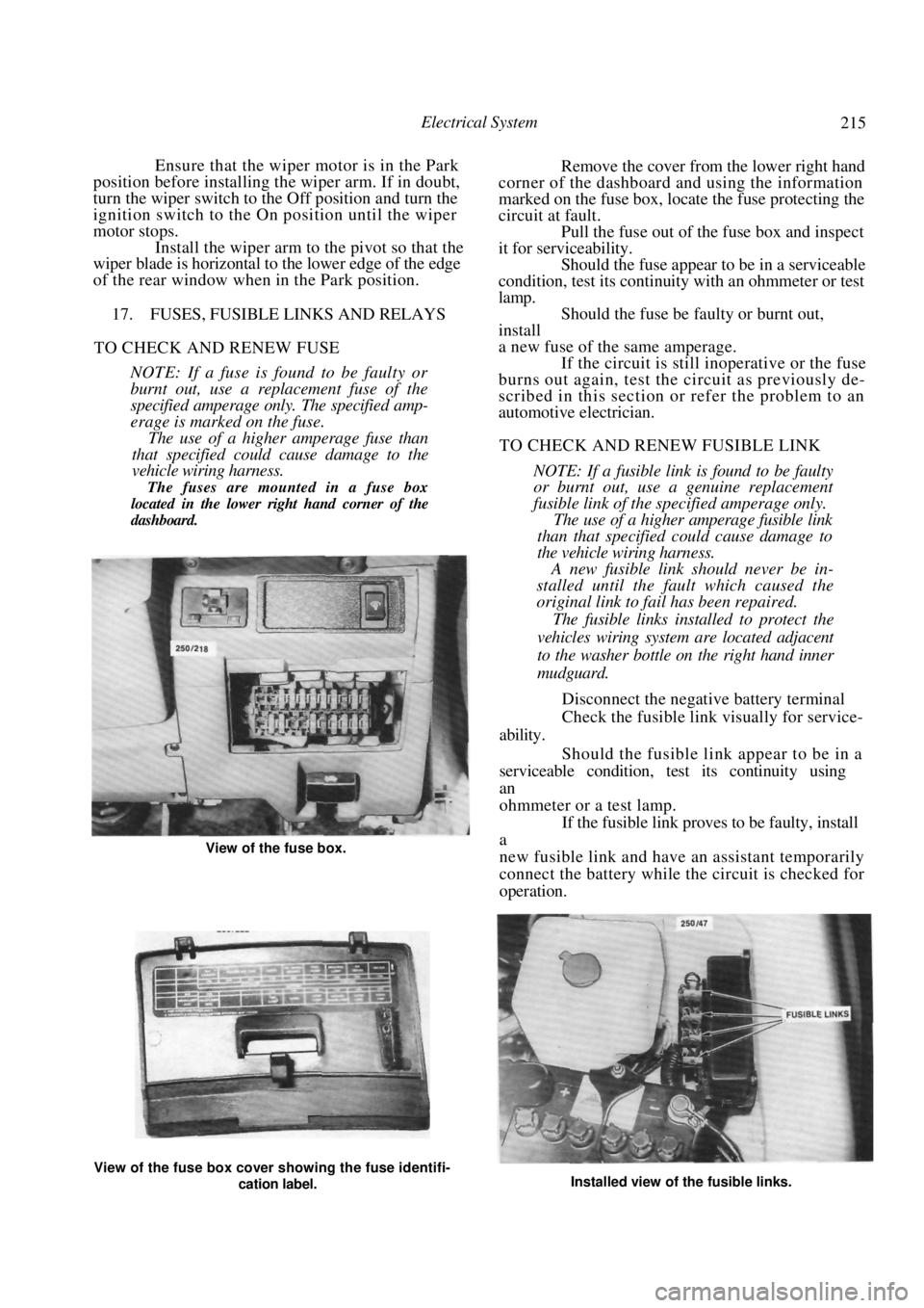
The fuses are mounted in a fuse box
located in the lower right hand corner of the
dashboard.
Remove the cover from the lower right hand
corner of the dashboard and using the information
marked on the fuse box, locate the fuse protecting the
circuit at fault. Pull the fuse out of the fuse box and inspect
it for serviceability.
Should the fuse appear to be in a serviceable
condition, test its continuity with an ohmmeter or test
lamp. Should the fuse be faulty or burnt out,
install
a new fuse of the same amperage. If the circuit is still inoperative or the fuse
burns out again, test the circuit as previously de-
scribed in this section or refer the problem to an
automotive electrician.
TO CHECK AND RENEW FUSIBLE LINK
NOTE: If a fusible link is found to be faulty
or burnt out, use a genuine replacement
fusible link of the specified amperage only.
The use of a higher amperage fusible link
than that specified could cause damage to
the vehicle wiring harness.
A new fusible link should never be in-
stalled until the fault which caused the
original link to fail has been repaired.
The fusible links installed to protect the
vehicles wiring system are located adjacent
to the washer bottle on the right hand inner
mudguard.
Disconnect the negative battery terminal
Check the fusible link visually for service-
ability.
Should the fusible link appear to be in a
serviceable condition, test its continuity using
an
ohmmeter or a test lamp. If the fusible link proves to be faulty, install
a
new fusible link and have an assistant temporarily
connect the battery while the circuit is checked for
operation.
View of the fuse box cover showing the fuse identifi-
cation label. Installed view of the fusible links.
View of the fuse box.