ignition NISSAN PULSAR 1987 Service Manual
[x] Cancel search | Manufacturer: NISSAN, Model Year: 1987, Model line: PULSAR, Model: NISSAN PULSAR 1987Pages: 238, PDF Size: 28.91 MB
Page 112 of 238
112 Fuel and Engine Management
If the voltage does not increase as specified, renew
the throttle position sensor.
If the voltage is as specified, proceed as follows.
(28) With the ignition switched On and the
throttle valve held fully open, measure the voltage at
control unit wiring connector terminal C13. The
voltage should be above 4 volts.
If the voltage is below 4 volts, renew the throttle
position sensor.
To Remove and Install
(1) Disconnect the negative battery terminal.
(2) On 1.6 liter engines, remove the air cleaner
assembly as previously described. (3) Disconnect the throttle position sensor wir-
ing connector. (4) Remove the throttle position sensor retain-
ing screws and remove the throttle position sensor
from the throttle body. Installation is a reversal of the removal procedure
with attention to the following points:
(1) Ensure that the throttle valve is in the fully
closed position. (2) Tighten the retaining screws securely and
install the wiring connector.
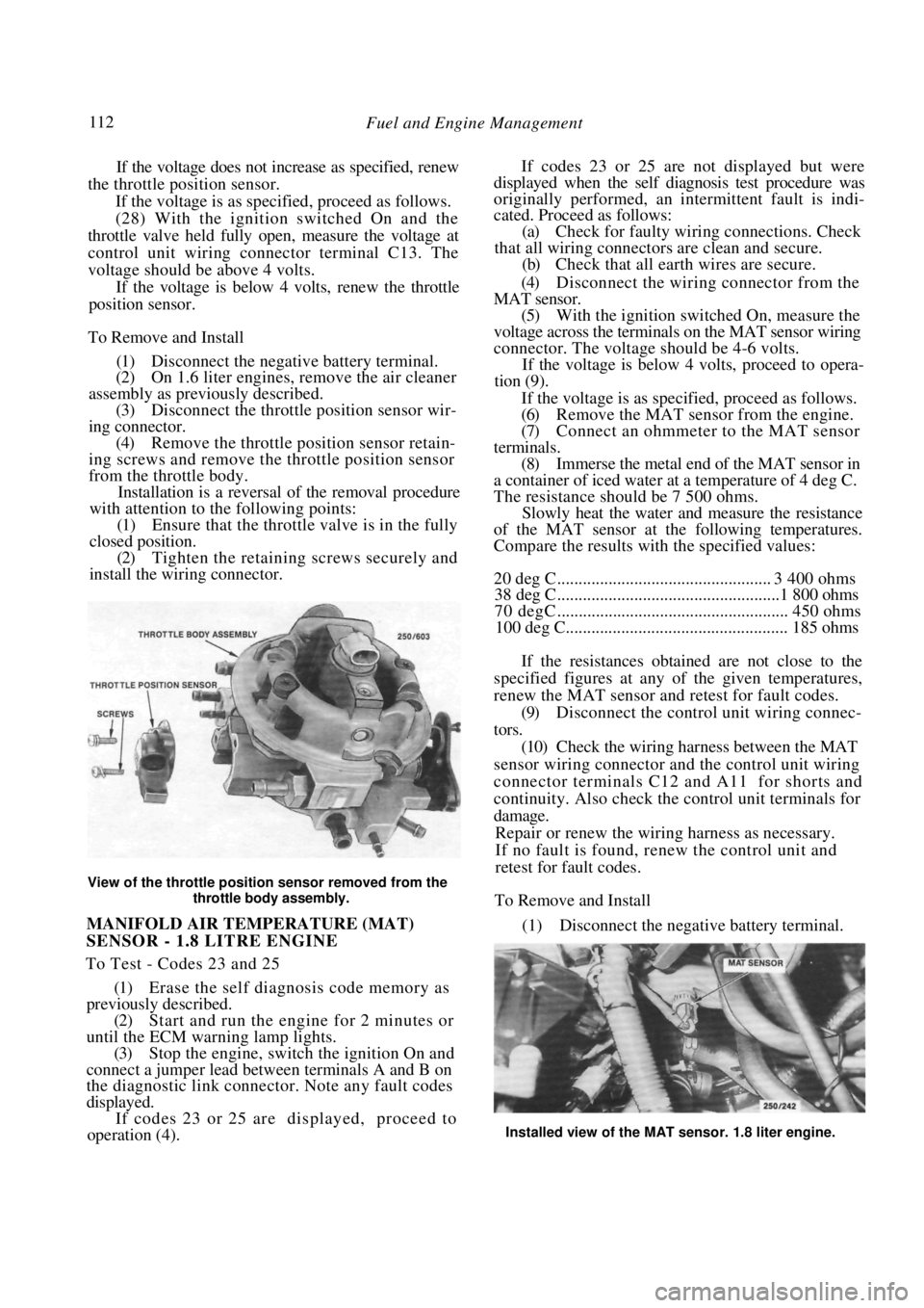
View of the throttle positi on sensor removed from the
throttle body assembly.
MANIFOLD AIR TEMPERATURE (MAT)
SENSOR - 1.8 LITRE ENGINE
To Test - Codes 23 and 25
(1) Erase the self diagnosis code memory as
previously described.
(2) Start and run the engine for 2 minutes or
until the ECM warning lamp lights. (3) Stop the engine, switch the ignition On and
connect a jumper lead between terminals A and B on
the diagnostic link connector . Note any fault codes
displayed. If codes 23 or 25 are displayed, proceed to
operation (4).
If codes 23 or 25 are not displayed but were
displayed when the self diagnosis test procedure was
originally performed, an intermittent fault is indi-
cated. Proceed as follows:
(a) Check for faulty wiri ng connections. Check
that all wiring connectors are clean and secure. (b) Check that all earth wires are secure.
(4) Disconnect the wiring connector from the
MAT sensor. (5) With the ignition switched On, measure the
voltage across the terminals on the MAT sensor wiring
connector. The voltage s hould be 4-6 volts.
If the voltage is below 4 volts, proceed to opera-
tion (9).
If the voltage is as specified, proceed as follows.
(6) Remove the MAT sensor from the engine.
(7) Connect an ohmmeter to the MAT sensor
terminals. (8) Immerse the metal end of the MAT sensor in
a container of iced water at a temperature of 4 deg C.
The resistance should be 7 500 ohms. Slowly heat the water and measure the resistance
of the MAT sensor at the following temperatures.
Compare the results with the specified values:
20 deg C .................................................. 3 400 ohms
38 deg C....................................................1 800 ohms
70 degC ...................................................... 450 ohms
100 deg C.................................................... 185 ohms
If the resistances obtained are not close to the
specified figures at any of the given temperatures,
renew the MAT sensor and retest for fault codes.
(9) Disconnect the control unit wiring connec-
tors. (10) Check the wiring harness between the MAT
sensor wiring connector and the control unit wiring
connector terminals C12 and A11 for shorts and
continuity. Also check the control unit terminals for
damage. Repair or renew the wiring harness as necessary.
If no fault is found, renew the control unit and
retest for fault codes.
To Remove and Install
(1) Disconnect the negative battery terminal.
Installed view of the MAT sensor. 1.8 liter engine.
Page 113 of 238

Fuel and Engine Management 113
(2) Disconnect the wiring connector from the
MAT sensor.
(3) Unscrew the sensor from the inlet manifold.
Installation is a reversal of the removal procedure
with attention to the following points:
(1) Apply Loctite 567 or a similar conductive
sealer to the threads of th e sensor. Tighten the sensor
to the specified torque. (2) Ensure that the wiring connector is clean and
tight.
OXYGEN SENSOR
To Test - Code 13
(1) Run the engine until the normal operating
temperature is obtained. (2) With the ignition switched Off, connect a
jumper lead between terminals A and B on the
diagnostic link connector.
(3) Start and run the engi ne at approximately
1 600-1 800 rpm for 2 minutes and note the ECM
warning lamp.
If the ECM warning lamp flashes at the rate of
twice per second, proceed to operation (5).
If the ECM warning lamp flashes at the rate of
once per second or slower, proceed as follows.
(4) Remove the jumper lead from the diagnostic
link connector and run th e engine above 2 000 rpm
for 2 minutes, noting the ECM warning lamp.
If the ECM warning lamp lights, stop the engine,
switch the ignition On and connect a jumper lead
between terminals A and B on the diagnostic link
connector. If code 13 is displayed proceed to opera-
tion (5).
If the ECM warning lamp does not light, an
intermittent fault is indicated. Proceed as follows:
(a) Check for faulty wiri ng connections. Check
that all wiring connectors are clean and secure.
(b) Check that all earth wires are secure.
(5) Switch the ignition Off and disconnect the
oxygen sensor wiring connector. Using a jumper lead
connect the oxygen sensor wiring connector to a
suitable engine earth. (6) Start and run the engi ne at approximately
1 600-1 800 rpm and note the ECM warning lamp.
The lamp may flash for a few seconds but should then
extinguish for at least 30 seconds.
If the ECM warning lamp functions as described,
proceed to operation (7).
If the ECM warning lamp does not function as
described proceed as follows:
(a) Check the wiring harness between the oxygen
sensor wiring connector and the control unit wiring
connector D7 for open circuits. Repair or renew the
wiring harness as necessary.
{b) Check the earth circuit between the control
unit wiring connect D6 and the right rear cylinder
head bolts. Repair or renew the wiring harness as
necessary.
(c) If no fault is found in (a) and (b) renew the
control unit and retest for fault codes.
(7) Check the wiring harness earth circuit be-
tween the control unit wiring connector D6 and the
right rear cylinder head bolts. Repair or renew the
wiring harness as necessary.
If no fault is found, thoroughly check the oxygen
sensor connector. If the conne ctor is not faulty, renew
the oxygen sensor.
To Test - Code 44
(1) Run the engine until normal operating tem-
perature is attained.
(2) With the ignition switched Off, connect a
jumper lead between terminals A and B on the
diagnostic link connector. (3) Start and run the engi ne at approximately
1 600-1 800 rpm for 2 minutes and note the ECM
warning lamp. If the ECM warning lamp is off more than on or
flashes at the rate of twice per second, proceed to
operation (4).
If the ECM warning lamp flashes evenly at the
rate of once per second an intermittent fault is
indicated. Proceed as follows:
(a) Check for faulty wiri ng connections. Check
that all wiring connectors are clean and secure. (b) Check that all earth wires are secure.
(4) Switch the engine Off and disconnect the
oxygen sensor wiring connector.
(5) Start and run the engine at 1 600-1 800 rpm
for at least 30 seconds and note the ECM warning
lamp. If the ECM warning lamp flashes at the rate of
twice per second procee d to operation (6).
If the ECM warning lamp extinguishes for at least
30 seconds, check the wiring harness between the
oxygen sensor wiring connector and the control unit
wiring connector terminal D7 for shorts to earth.
Repair or renew the wiring harness as necessary.
If no fault can be found in the wiring harness, renew
the control unit.
Installed view of the oxygen sensor.
Page 114 of 238

114 Fuel and Engine Management
(6) Check the vehicle for the following:
(a) Low fuel pressure.
(b) Contaminated fuel.
(c) Vacuum leaks at the inlet manifold, engine
vacuum hoses and engine ventilation hoses. (d) Exhaust manifold leaks before the oxygen
sensor. (e) Correct MAP sensor operation.
(f) Blocked oxygen sensor metal vent cover eg.
plugged with mud etc. (g) Fuel injectors) partially blocked. Refer to a
fuel injection specialis t or a Nissan dealer.
If the above items have been checked and no
faults have been found, a faulty oxygen sensor is
indicated. Renew the oxygen sensor, run the engine
and ensure that no fault codes are set.
To Test — Code 45
(1) Run the engine until normal operating tem-
perature is attained. (2) With the ignition switched Off, connect a
jumper lead between terminals B and A on the
diagnostic link connector. (3) Start and run the engine at approximately
1 600-1 800 rpm for 2 minutes and note the ECM
warning lamp. If the ECM warning lamp is on more than off or
flashes at the rate of twice per second, proceed to the
following operation.
If the ECM warning lamp flashes evenly at the
rate of once per second an intermittent fault is
indicated. Proceed as follows:
(a) Check for faulty wiri ng connections. Check
that all wiring connectors are clean and secure. (b) Check that all earth wires are secure.
(4) Switch the engine Off and disconnect the
oxygen sensor wiring connector. (5) Using a jumper lead, connect the oxygen
sensor wiring connector to a suitable engine earth. (6) Start and run the engine at 1 600-1 800 rpm
and note the ECM warning lamp.
If the ECM warning lamp extinguishes for at least
30 seconds, proceed to operation (7).
If the ECM warning lamp flashes on more than off
or flashes at the rate of twice per second, switch the
engine Off and disconnect the control unit wiring
connectors. Using an ohmmeter, check that there is no
resistance between the co ntrol unit wiring connector
terminal D6 and earth. Repair or renew the wiring as
necessary.
If no fault can be found in the wiring harness,
renew the control unit.
NOTE: The wiring harness for terminal D6
earths through the righ t hand rear cylinder
head bolt.
(7) Check the vehicl e for the following:
(a) High fuel pressure.
(b) Leaking injector(s).
(c) Faulty ignition wiring.
(d) Charcoal canister purge system blocked or
restricted.
(e) Faulty coolant temper ature sensor circuit.
(f) Faulty MAT sensor circuit (1.8 liter engine).
(g) MAP sensor operation.
(h) Throttle position sensor operation.
If the above items have been checked and no
faults have been found, a faulty oxygen sensor is
indicated.
Renew the oxygen sensor, run the engine and
ensure that no fault codes are set.
To Remove and Install
(1) If the engine is cold, run the engine for
approximately two minutes to allow easy oxygen
sensor removal. (2) Disconnect the negative battery terminal and
the oxygen sensor connector.
View of the oxygen sensor removed from the exhaust
manifold.
(3) Remove the exhaust manifold heat shield
retaining bolts and remove the heat shield from the
engine.
(4) Remove the oxygen sensor with a short ring
spanner using care not to damage the sensor wire. Installation is a reversal of the removal procedure
with attention to the following points:
(1) When installing a sensor that has previously
been removed, coat the sen sor threads with anti-seize
compound. Nissan recommend a mixture of liquid
graphite and glass beads. (2) Install the sensor and tighten to the specified
torque. (3) Connect the electrical connector ensuring
that the wiring is secured away from the exhaust. (4) Install the heat shield and tighten the retain-
ing bolts securely. On 1.6 liter engines, ensure that the hot air inlet
tube is located correctly be tween the heat shield and
the air cleaner housing.
(5) Start the engine and check for leaks.
VEHICLE SPEED SENSOR
To Test - Code 24
(1) Check the fuel pump and meter fuses. If the
fuses are serviceable, proceed to operation (5). If a
fuse is blown, rectify the cause and renew the fuse.
Page 115 of 238

Fuel and Engine Management 115
Erase the fault codes and retest for fault codes as
follows:
(2) Start and run the engine until normal oper-
ating temperature is attained. (3) Drive the vehicle at a speed of at least 80
km/h and, with the throttle closed, allow the vehicle to
decelerate until the engine speed is below 1 500 rpm.
NOTE: After rectifying any fault it will be
necessary to retest for fault codes. To test for
Code 24 the vehicle must be driven as
previously described.
(4) Switch the engine Off and connect a jumper
lead between terminals A and B on the diagnostic link
connector. Switch the ignition On and note the fault
codes. If code 24 is displayed proceed as follows. (5) Check the operation of the speedometer and
the instrument cluster warning lamps. If the speed-
ometer only is not functioning, proceed to operation
(13).
If the speedometer and the instrument cluster
warning lamps are not functioning, a fault in the
instrument cluster wiring harness is indicated. Refer
the fault to an auto electrical workshop or a Nissan
dealer.
If the speedometer is functioning, proceed as
follows:
(6) Raise the front of the vehicle and support it
on chassis stands. (7) Place the transaxle in Neutral and switch the
ignition On. (8) With the aid of assistants, slowly spin the
front wheels by hand while backprobing the control
unit wiring connector terminal A10 with a digital
voltmeter to earth. The voltage should alternate from under 1 volt to
over 10 volts.
If the voltmeter readi ng is not as specified,
proceed to operation (9).
If the voltmeter reading is as specified, the vehicle
speed sensor is operating satisfactorily, indicating an
intermittent fault was the cause of the fault code.
Proceed as follows:
(a) Check for faulty wiri ng connections. Check
that all wiring connectors are clean and secure. (b) Check that all earth c onnections are secure.
(9) Remove the instrument cluster as described
in the Electrical System section. (10) With the ignition switched On, backprobe
the control unit wiring connector terminal A10 with a
voltmeter to earth. The voltage should be over 10
volts. If the voltage is less than specified, check the
wiring harness for shorts to earth between the black
and yellow wire terminal on the instrument cluster
wiring connector and the control unit connector
terminal A10. Repair or renew the wiring harness as
necessary. If no fault can be found, renew the control
unit.
(11) With the ignition switched On, backprobe
the black and yellow wire terminal on the instrument
cluster wiring connector with a voltmeter to earth.
The voltage should be over 10 volts.
If the voltage is less than specified, locate the open
circuit between the instrument cluster black and
yellow wire terminal and the control unit wiring
connector terminal A10. Repair or renew the wiring
harness as necessary.
(12) With a test lamp connected to 12 volts,
backprobe the black wire terminals on the instrument
cluster wiring connectors. The test lamp should light.
If the test lamp does not light locate the open
circuit between the black wire terminals and earth.
Repair or renew the wiring harness as necessary.
If the test lamp does light, renew the signal
divider circuit board which is located in the instru-
ment cluster.
(13) With the ignition switched On and the
engine not running, disconnect the vehicle speed
sensor wiring connector from the harness connector.
(14) With a test lamp connected to earth, probe
the yellow wire terminal on the harness wiring con-
nector. The test lamp should light. If the test lamp does not light, locate the open
circuit between the yellow wi re terminal and the Fuel
Pump fuse. Repair or renew the wiring harness as
necessary.
(15) With a test lamp connected to 12 volts,
probe the black wire terminal on the harness wiring
connector. The test lamp should light.
If the test lamp does not light, locate the open
circuit between the black wire terminal and earth.
Repair or renew the wiring harness as necessary.
(16) Using a voltmeter measure the voltage at the
red wire terminal on the harness wiring connector.
If the voltage is 5-9 volts proceed to operation
(19).
If the voltage is over 9 vol ts proceed to operation
(18).
Installed view of the vehicle speed sensor.
Page 148 of 238
148 Steering — Part 2
3. STEERING COLUMN
Special Equipment Required:
To Remove Steering Wheel — Steering wheel
puller
TO REMOVE AND INSTAL
(1) Disconnect the negative battery terminal.
(2) Working in the engine compartment, mark
the relationship between the steering shaft universal
coupling joint and the steering gear pinion shaft. (3) Remove the pinch bolts from the universal
joint. (4) Working inside the vehi cle, remove the steer-
ing wheel as previously described. (5) Remove the steering column shroud screws,
unclip the lower and upper covers and remove them
from the steering column. (6) Disconnect all the steering column wiring
connectors. (7) Remove the lower trim from underneath the
steering column.
(8) Fold back the insulator and remove the nuts
from the steering colu mn floor bracket.
(9) Remove the nuts from the lower steering
column bracket. (10) Remove the bolts from the tilt bracket
assembly. (11) Maneuver the steering column from the
vehicle.
Installation is a reversal of the removal procedure
with attention to the following points:
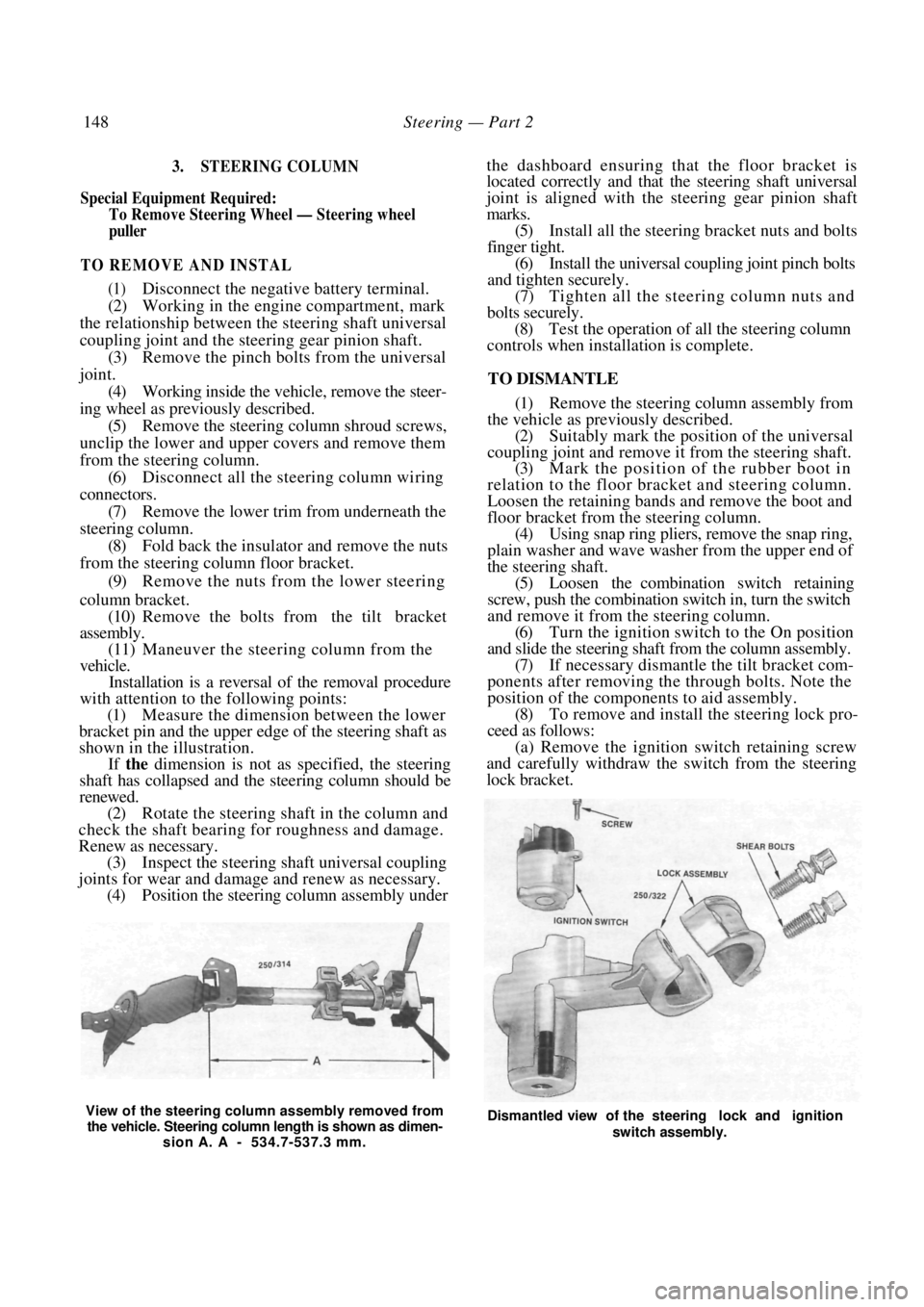
(1) Measure the dimension between the lower
bracket pin and the upper edge of the steering shaft as
shown in the illustration.
If the dimension is not as specified, the steering
shaft has collapsed and the steering column should be
renewed.
(2) Rotate the steering shaft in the column and
check the shaft bearing for roughness and damage.
Renew as necessary. (3) Inspect the steering shaft universal coupling
joints for wear and damage and renew as necessary. (4) Position the steering column assembly under
the dashboard ensuring that the floor bracket is
located correctly and that the steering shaft universal
joint is aligned with the steering gear pinion shaft
marks.
(5) Install all the steering bracket nuts and bolts
finger tight. (6) Install the universal coupling joint pinch bolts
and tighten securely.
(7) Tighten all the stee ring column nuts and
bolts securely. (8) Test the operation of all the steering column
controls when installation is complete.
TO DISMANTLE
(1) Remove the steering column assembly from
the vehicle as previously described. (2) Suitably mark the position of the universal
coupling joint and remove it from the steering shaft. (3) Mark the position of the rubber boot in
relation to the floor bracket and steering column.
Loosen the retaining bands and remove the boot and
floor bracket from th e steering column.
(4) Using snap ring pliers, remove the snap ring,
plain washer and wave washer from the upper end of
the steering shaft. (5) Loosen the combination switch retaining
screw, push the combination switch in, turn the switch
and remove it from the steering column. (6) Turn the ignition switch to the On position
and slide the steering shaft from the column assembly. (7) If necessary dismantle the tilt bracket com-
ponents after removing the through bolts. Note the
position of the components to aid assembly. (8) To remove and install the steering lock pro-
ceed as follows: (a) Remove the ignition switch retaining screw
and carefully withdraw the switch from the steering
lock bracket.
View of the steering column assembly removed from
the vehicle. Steering column length is shown as dimen- sion A. A - 534.7-537.3 mm. Dismantled view of the steering lock and ignition
switch assembly.
Page 149 of 238
Steering — Part 2 149
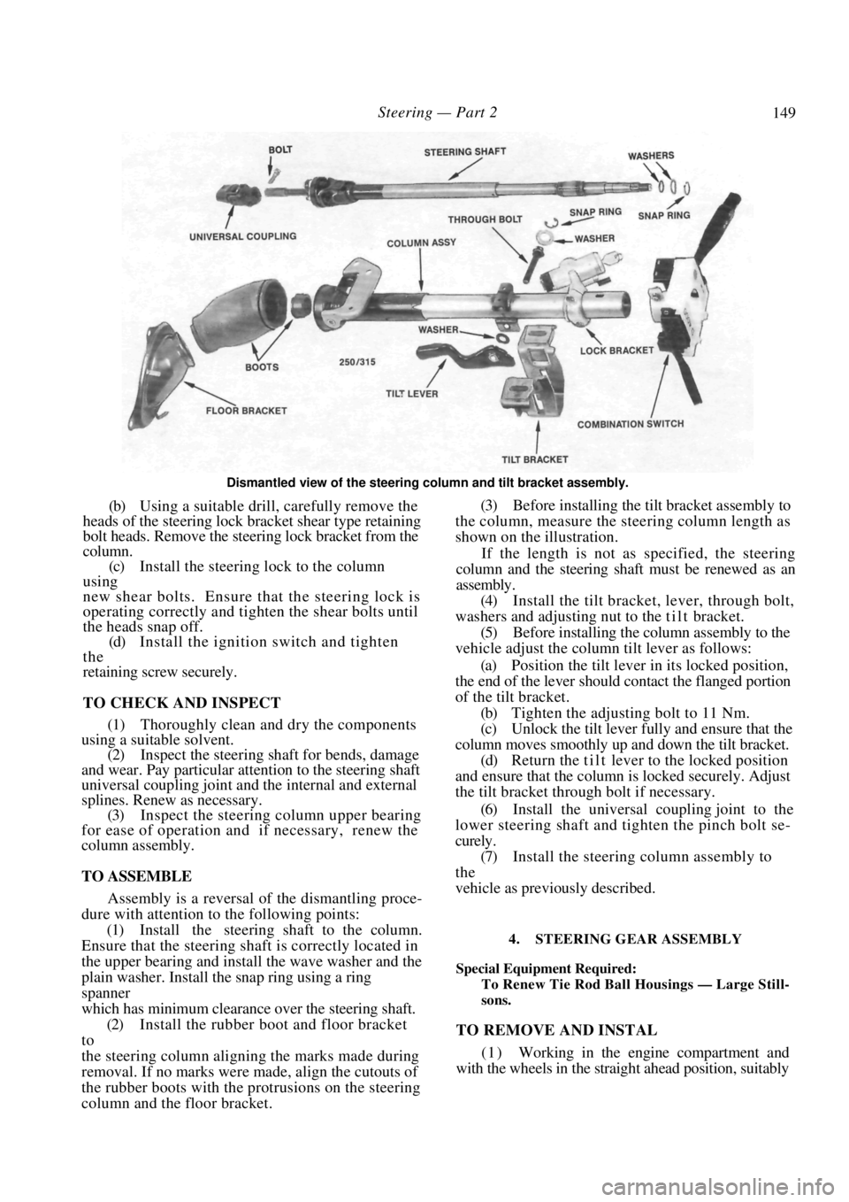
Dismantled view of the steering column and tilt bracket assembly.
(b) Using a suitable drill, carefully remove the
heads of the steering lock br acket shear type retaining
bolt heads. Remove the steering lock bracket from the
column.
(c) Install the steering lock to the column
using
new shear bolts. Ensure that the steering lock is
operating correctly and tigh ten the shear bolts until
the heads snap off.
(d) Install the ignition switch and tighten
the
retaining screw securely.
TO CHECK AND INSPECT
(1) Thoroughly clean and dry the components
using a suitable solvent.
(2) Inspect the steering shaft for bends, damage
and wear. Pay particular attention to the steering shaft
universal coupling joint and the internal and external
splines. Renew as necessary. (3) Inspect the steering column upper bearing
for ease of operation and if necessary, renew the
column assembly.
TO ASSEMBLE
Assembly is a reversal of the dismantling proce-
dure with attention to the following points:
(1) Install the steering shaft to the column.
Ensure that the steering shaft is correctly located in
the upper bearing and insta ll the wave washer and the
plain washer. Install the snap ring using a ring
spanner
which has minimum clearan ce over the steering shaft.
(2) Install the rubber boot and floor bracket
to
the steering column aligning the marks made during
removal. If no marks were made, align the cutouts of
the rubber boots with the protrusions on the steering
column and the floor bracket. (3) Before installing the tilt bracket assembly to
the column, measure the steering column length as
shown on the illustration.
If the length is not as specified, the steering
column and the steering shaft must be renewed as an
assembly.
(4) Install the tilt bracket, lever, through bolt,
washers and adjusting nu t to the t i l t bracket.
(5) Before installing the column assembly to the
vehicle adjust the column tilt lever as follows:
(a) Position the tilt lever in its locked position,
the end of the lever should contact the flanged portion
of the tilt bracket.
(b) Tighten the adjusting bolt to 11 Nm.
(c) Unlock the tilt lever fully and ensure that the
column moves smoothly up and down the tilt bracket. (d) Return the tilt lever to the locked position
and ensure that the column is locked securely. Adjust
the tilt bracket thro ugh bolt if necessary.
(6) Install the universal coupling joint to the
lower steering shaft and tighten the pinch bolt se-
curely.
(7) Install the steering column assembly to
the
vehicle as previously described.
4. STEERING GEAR ASSEMBLY
Special Equipment Required:
To Renew Tie Rod Ball Housings — Large Still-
sons.
TO REMOVE AND INSTAL
( 1 ) Working in the engine compartment and
with the wheels in the straight ahead position, suitably
Page 187 of 238
Brakes 187
(b) Disengage the handbrake cable return spring
from the backing plate.
plate and remove the cable from the vehicle.
(6) Inspect the rear handbrake cables for chafing
or broken strands. Renew the cables if damage is
evident.
Installation is a reversal of the removal procedure
with attention to the following points:
(1) Ensure that the handbrake cable clamps are
correctly installed. (2) On drum brake models, install the
handbrake
cable to the backing plate by carefully tapping the
flange on the handbrake cable. Ensure that the cable is
not damaged. (3) Adjust the handbrake cable as described
under the Brake Adjustments heading.
9. BRAKE ADJUSTMENTS
FRONT AND REAR DISC BRAKES
The disc brakes are self adjusting and no manual
adjustment is required or provided.
REAR DRUM BRAKES
Depress the handbrake lever button, apply and
release the handbrake lever several times to adjust the
rear brake shoes.
HANDBRAKE
(1) Raise the rear of the vehicle and support it
on chassis stands. (2) Remove the carpet square from the rear of
the console. Remove the retaining screws from the
front and rear of the rear console section and manoeu-
vre the rear console from the vehicle. (3) Tighten the adjusting nut until the hand-
brake lever pull is between 7-11 notches. (4) Check that the rear wheels are not binding. If
the rear wheels do not rotate freely refer to the Brakes
Trouble Shooting for possible causes.
(5) With the ignition switched On, check that
the handbrake warning lamp is extinguished when the
lever is fully released. (6) Lower the vehicle to the ground and test the
handbrake on an incline.
10. BRAKE PEDAL
TO REMOVE AND INSTAL
(1) Working inside the vehicle remove the re-
taining clip from the clevis pin and remove the clevis
pin connecting the brake pedal to the pushrod.
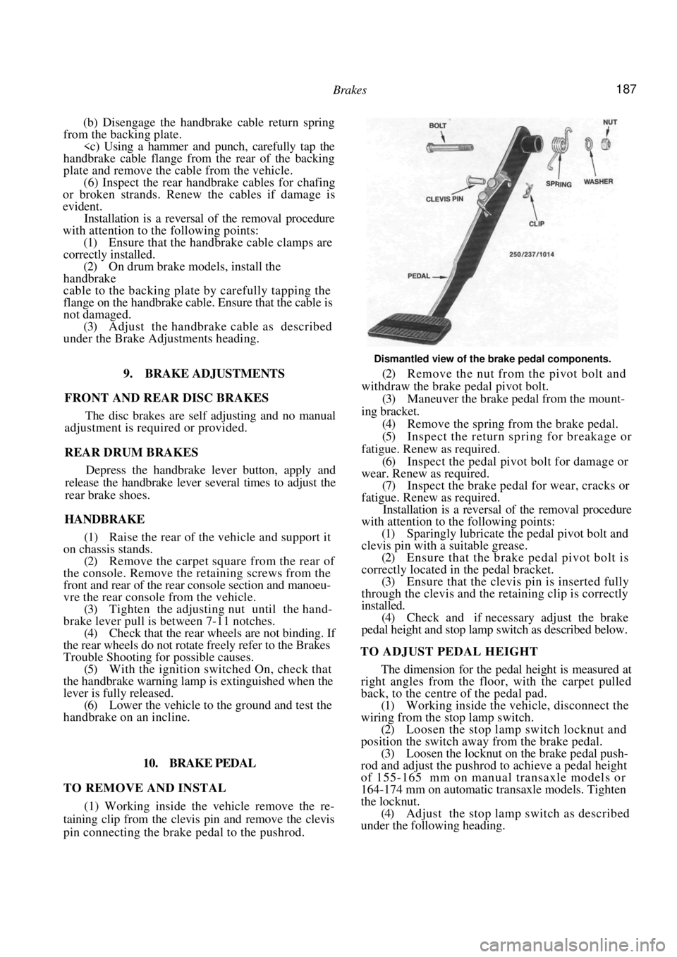
Dismantled view of the brake pedal components.
(2) Remove the nut from the pivot bolt and
withdraw the brake pedal pivot bolt.
(3) Maneuver the brake pedal from the mount-
ing bracket. (4) Remove the spring from the brake pedal.
(5) Inspect the return spring for breakage or
fatigue. Renew as required.
(6) Inspect the pedal pivot bolt for damage or
wear. Renew as required. (7) Inspect the brake pedal for wear, cracks or
fatigue. Renew as required. Installation is a reversal of the removal procedure
with attention to the following points:
(1) Sparingly lubricate the pedal pivot bolt and
clevis pin with a suitable grease. (2) Ensure that the brake pedal pivot bolt is
correctly located in the pedal bracket. (3) Ensure that the clevis pin is inserted fully
through the clevis and the retaining clip is correctly
installed. (4) Check and if necessary adjust the brake
pedal height and stop lamp switch as described below.
TO ADJUST PEDAL HEIGHT
The dimension for the pedal height is measured at
right angles from the floor, with the carpet pulled
back, to the centre of the pedal pad.
(1) Working inside the ve hicle, disconnect the
wiring from the stop lamp switch.
(2) Loosen the stop lamp switch locknut and
position the switch away from the brake pedal. (3) Loosen the locknut on the brake pedal push-
rod and adjust the pushrod to achieve a pedal height
of 155-165 mm on manual transaxle models or
164-174 mm on automatic transaxle models. Tighten
the locknut. (4) Adjust the stop lamp switch as described
under the following heading.
Page 190 of 238

190
ELECTRICAL SYSTEM
CAUTION: To prevent severe electrical shock extreme care must be taken when
working on or near the electronic ignition system as dangerous high tension voltages
are produced in both the primary and secondary circuits. See the text fo\
r
precautionary notes.
SPECIFICATIONS
BATTERY
Type ..................................................12 volt lead acid
Polarity to earth .................................... Negative ( - )
Specific gravity:
Fully charged ................................... A bove 1.250
Fully discharged ................................Below 1.130
ALTERNATOR
Make .................................................Bosch or Hitachi
Maximum output .......................................... 70 amps
Polarity to earth .................................... Negative ( - )
Stator windings ......................................... Star wound
Regulator type ................................................ Integral
Brush length minimum:
Bosch ........................................................ 5.0 mm
Hitachi ............................. 6.0 mm or limit mark
STARTER MOTOR
Make .................................................Hitach i or Bosch
Type ............................ 4 pole 4 brush reduction gear
Operation control.................................. Solenoid and
overrunning clutch
Undercut of commutator (maximum):
Hitachi ...................................................... 0.8 mm
Brush length (minimum):
Bosch ........................................................ 8.0 mm
Hitachi ........................................................11 mm
Brush spring tension;
Hitachi ............................................... 15.7-19.6 N
Hitachi:
Drive pinion stopper clearance ........ 0.3-1.5 mm
Selective fit adjuster plates ........ 0.5 and 0.8 mm
IGNITION SYSTEM
The ignition system is an integral part of the
engine management system. The Specifications, testing
and overhaul procedures are fully covered in the Fuel
and Engine Management section.
TORQUE WRENCH SETTINGS
Alternator pulley retaining nut:
Bosch ......................................................... 50 Nm
Hitachi ....................................................... 59 Nm
1. BATTERY AND CHARGING SYSTEM
TROUBLE SHOOTING
BATTERY UNDERCHARGED
3. Loose or broken drive belt: Adjust or renew
the drive belt. 4. Faulty alternator regulator; Renew the regu-
lator unit.
5. Faulty battery: Install a new battery of
the
recommended type and capacity. 6. Faulty alternator: Overhaul or renew the
alternator. 7. Fault in the charging circuit wiring: Check
and repair or renew the wiring harness. 8. Faulty connections in the charging circuit:
Check and repair the connections. 9. Fusible link blown; Rectify the fault and
renew as necessary.
NOTE: Check the state of charge (specific
gravity) of the battery- as described under
the
Battery heading in this section. If the battery
is undercharged, check the possible causes in
the order given.
BATTERY OVERCHARGED
• Faulty alternator regulator unit:
Renew the
regulator unit.
• Faulty alternator: Overhaul or
renew the
alternator. • Faulty charging circuit wiring or
connec-
tions: Check and renew or repair the faulty
compo-
nents.
NOTE: An overcharged battery is indicated
by continual loss of water through boiling.
Page 192 of 238
192 Electrical System
transaxle models, check for a faulty or incorrectly
adjusted neutral safety switch.
1. Discharged battery: Check for a fault or short
circuit in the system. 2. Battery fully charged but will not crank
engine. Check for a locked drive and ring gear,
internal starter faul t or seized engine.
3. Fusible link blown: Check and repair the
cause and renew as necessary.
NOTE: Rotate the engine by hand to ensure
that the starter drive is not locked with the
flywheel ring gear and t hat the engine is not
seized. Ensure that the ignition key is
turned off before rotating the engine.
3. LIGHTING SYSTEM TROUBLE SHOOTING
LAMP OR LAMPS FAIL TO LIGHT
1. Faulty bulb(s): Check and renew the faulty
bulb(s). 2. Open circuit in the wiring or connections:
Check the lamp circuits and rectify as necessary.
1. Faulty lamp switch: Check and if necessary
renew the lamp switch. 2. Faulty fuse or fuse connection: Repair the
fuse connection or renew the fuse. 3. Lamp relay faulty: Check and renew as
necessary.
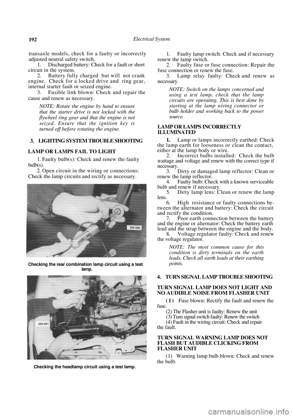
NOTE: Switch on the lamps concerned and
using a test lamp, check that the lamp
circuits are operating. This is best done by
starting at the lamp wiring connector or
bulb holder and work ing back to the power
source.
LAMP OR LAMPS INCORRECTLY
ILLUMINATED
1. Lamp or lamps incorrectly earthed: Check
the lamp earth for loosene ss or clean the contact,
either at the lamp body or wire.
2. Incorrect bulbs installe d: Check the bulb
wattage and voltage and renew with the correct type if
necessary. 3. Dirty or damaged lamp reflector: Clean or
renew the lamp reflector. 4. Faulty bulb: Check with a known serviceable
bulb and renew if necessary. 5. Dirty lamp lens: Clean or renew the lamp
lens. 6. High resistance or faulty connections be-
tween the alternator and battery: Check the circuit
and rectify th e condition.
7. Poor earth connection between the battery
and the engine or alternat or: Check the battery earth
lead and the strap between the engine and the body. 8. Voltage regulator faulty: Check and renew
the voltage regulator.
NOTE: The most common cause for this
condition is dirty t erminals on the earth
leads. Check all earth leads at their earthing
points.
4. TURN SIGNAL LAMP TROUBLE SHOOTING
TURN SIGNAL LAMP DOES NOT LIGHT AND
NO AUDIBLE NOISE FROM FLASHER UNIT
(1) Fuse blown: Rectify the fault and renew the
fuse.
(2) The Flasher unit is faulty: Renew the unit
(3) Turn signal switch faulty: Renew the switch
(4) Fault in the wiring circuit: Check and repair
the fault.
TURN SIGNAL WARNING LAMP DOES NOT
FLASH BUT AUDIBLE CLICKING FROM
FLASHER UNIT
(1) Warning lamp bulb blown: Check and renew
the bulb.
Checking the rear combination lamp circuit using a test
lamp.
Checking the headlamp circuit using a test lamp.
Page 193 of 238
Electrical System 193
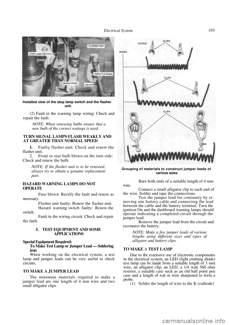
Installed view of the stop lamp switch and the flasher
unit.
(2) Fault in the warning lamp wiring: Check and
repair the fault.
NOTE: When renewing bulbs ensure that a
new bulb of the correct wattage is used.
TURN SIGNAL LAMPS FLASH WEAKLY AND
AT GREATER THAN NORMAL SPEED
1. Faulty flasher unit: Check and renew the
flasher unit.
2. Front or rear bulb blown on the turn side:
Check and renew the bulb.
NOTE: If the flasher unit is to be renewed,
always try to obtain a genuine replacement
part.
HAZARD WARNING LAMPS DO NOT
OPERATE
Fuse blown: Rectify the fault and renew as
necessary.
Flasher unit faulty: Re new the flasher unit.
Hazard warning switch faulty: Renew the
switch.
Fault in the wiring circuit: Check and repair
the fault.
5. TEST EQUIPMENT AND SOME APPLICATIONS
Special Equipment Required:
To Make Test Lamp or Jumper Lead — Soldering
iron
When working on the electrical system, a test
lamp and jumper leads can be very useful to check
circuits.
TO MAKE A JUMPER LEAD
The minimum materials required to make a
jumper lead are one length of 4 mm wire and two
small alligator clips.
Grouping of materials to construct jumper leads of
various sizes.
Bare both ends of a suitable length of 4 mm
wire. Connect a small alligato r clip to each end of
the wire. Solder and tape the connections. Test the jumper lead for continuity by re-
moving one battery cable and connecting the lead
between the cable and the battery terminal. Turn the
ignition On and the dashboard warning lamps should
operate indicating a completed circuit through the
jumper lead. Remove the jumper lead from the circuit and
reconnect the battery.
NOTE: Make a few jumper leads of various
lengths using different sizes and types of
alligator and battery clips.
TO MAKE A TEST LAMP
Due to the extensive use of electronic components
in the electrical system, an LED (light emitting diode)
test lamp can be made from a suitable length of 3 mm
wire, an alligator clip, an LED, a 1/4 watt 560 ohm
resistor, a suitable case such as an old ball point pen
case and a length of rod or wire sharpened to form a
probe.
(1) Solder the length of wire to the K (cathode)