ignition NISSAN PULSAR 1987 Repair Manual
[x] Cancel search | Manufacturer: NISSAN, Model Year: 1987, Model line: PULSAR, Model: NISSAN PULSAR 1987Pages: 238, PDF Size: 28.91 MB
Page 194 of 238
194 Electrical System
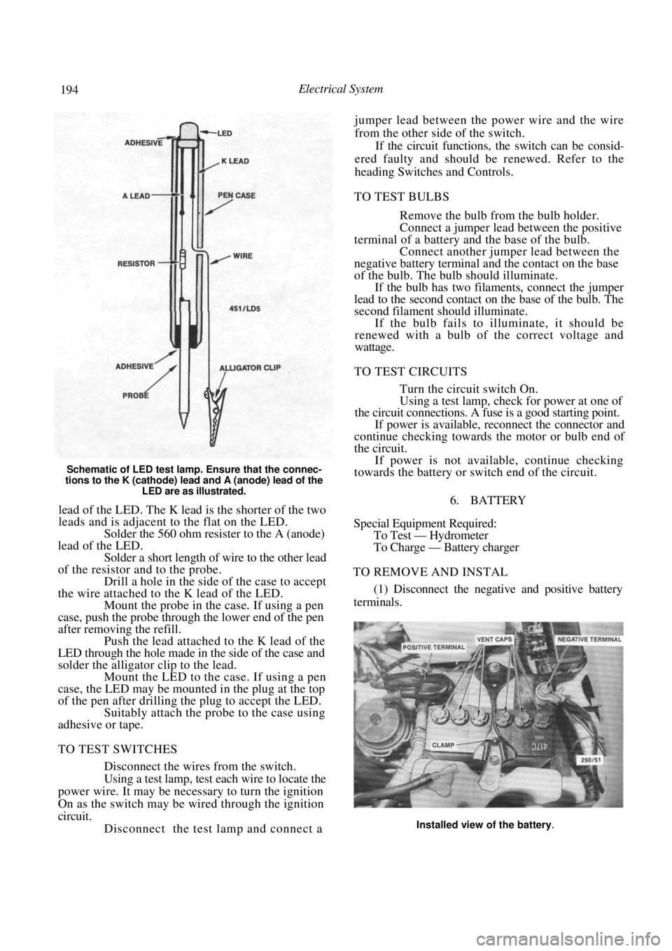
Schematic of LED test lamp. Ensure that the connec-
tions to the K (cathode) lead and A (anode) lead of the LED are as illustrated.
lead of the LED. The K lead is the shorter of the two
leads and is adjacent to the flat on the LED.
Solder the 560 ohm resister to the A (anode)
lead of the LED. Solder a short length of wire to the other lead
of the resistor and to the probe. Drill a hole in the side of the case to accept
the wire attached to the K lead of the LED. Mount the probe in the case. If using a pen
case, push the probe through the lower end of the pen
after removing the refill. Push the lead attached to the K lead of the
LED through the hole made in the side of the case and
solder the alligator clip to the lead.
Mount the LED to the case. If using a pen
case, the LED may be mounted in the plug at the top
of the pen after drilling the plug to accept the LED. Suitably attach the probe to the case using
adhesive or tape.
TO TEST SWITCHES
Disconnect the wires from the switch.
Using a test lamp, test each wire to locate the
power wire. It may be nec essary to turn the ignition
On as the switch may be wired through the ignition
circuit. Disconnect the test lamp and connect a jumper lead between the power wire and the wire
from the other side of the switch.
If the circuit functions, the switch can be consid-
ered faulty and should be renewed. Refer to the
heading Switches and Controls.
TO TEST BULBS
Remove the bulb from the bulb holder.
Connect a jumper lead between the positive
terminal of a battery a nd the base of the bulb.
Connect another jumper lead between the
negative battery terminal and the contact on the base
of the bulb. The bulb should illuminate. If the bulb has two filaments, connect the jumper
lead to the second contact on the base of the bulb. The
second filament should illuminate.
If the bulb fails to illuminate, it should be
renewed with a bulb of the correct voltage and
wattage.
TO TEST CIRCUITS
Turn the circuit switch On.
Using a test lamp, check for power at one of
the circuit connections. A fuse is a good starting point.
If power is available, reconnect the connector and
continue checking towards the motor or bulb end of
the circuit.
If power is not available, continue checking
towards the battery or switch end of the circuit.
6. BATTERY
Special Equipment Required: To Test — Hydrometer
To Charge — Battery charger
TO REMOVE AND INSTAL
(1) Disconnect the negative and positive battery
terminals.
Installed view of the battery.
Page 201 of 238

Electrical System 201
nosed pliers. This will safeguard the diodes
by transferring any excess heat to the jaws of
the pliers.
Using a suitable drift, install the bearing into
the drive end bracket, install the retainer plate and
screws. Tighten the screws securely. Using a suitable press and press plates, install
the bearing to the slip ring end of the rotor shaft.
Ensure that pressure is ex erted only on the inner race
and that the stop ring groove is nearest to the sl i p
rings. Ensure that the rotor sh aft rear bearing stop
ring is positioned so that the protruding part of the
ring is located in the deepest part of the groove. Install the stator, diode pack and
regulator
assembly to the slip ring e nd bracket. Install the
retaining nuts and washers and tighten securely. Install the nut and insulator to the terminal
and tighten securely. Using a piece of wire, hold the brushes in a
retracted position. Hold the drive end bracket in a soft jawed
vice and install the rotor shaft assembly to the drive
end bracket. Install the pulley, retaining nut and washer to
the rotor shaft and tighten the retaining nut to the
specified torque. Apply a heated 200 watt soldering iron to the
slip ring end bracket at the bearing mounting boss for
3-4 minutes to heat the bracket and allow the
installation of the rotor shaft rear bearing. Aligning the marks made on dismantling and
ensuring that the rotor sh aft rear bearing retaining
ring protrusion is located in the deepest part of its
groove, install the rotor/stator assembly to the slip ring
end bracket.
Remove the brush retr acting wire from the
alternator, ensure that the alternator component
marks are aligned, install the retaining through bolts
and tighten them securely. Check the alternator rotor for smooth oper-
ation and install the al ternator to the vehicle
as
previously described.
Check the alternator operation on the vehicle
as previously described.
8. STARTER MOTOR
Special Equipment Required:
To Renew Brushes — Soldering iron
To Renew Armature Bearings — Bearing puller
DESCRIPTION
Two types of starter motors are installed to the
range of vehicles covere d by this manual, either
Hitachi or Bosch.
The starter motor is the induced pole type with
four brushes and four pole shoes with field coils.
A solenoid switch is attached to the starter drive
end bracket. The solenoid plunger is connected to
the overrunning clutch and drive pinion assembly
through a lever and pivot arrangement.
When the solenoid windings are energized, the
plunger acting on the lever and pivot engages the drive
pinion with the flywheel ri ng gear and at the same
time closes the switch supplying power from the
positive lead of the battery to the starter motor field
coils and armature to operate the motor.
As the engine fires, the over-running clutch of the
drive pinion assembly prevents high speed rotation of.
and possible damage to, the starter armature if the
solenoid windings are not immediately de-energized
by releasing the ignition key.
The starter solenoid switch windings are energized
by the ignition switch.
TO TEST ON VEHICLE
Should the starter motor fail to operate when the
ignition switch is turned to the Start position, check
the following points:
Check the battery condition and state of
charge. Refer to the Battery heading for the correct
procedure.
Clean the battery terminals, taking particular
care to remove the scale from the positive ( + )
terminal post and terminal. Check the earth connection for tightness and
cleanliness.
Switch on the headlamps and turn the igni-
tion switch to Start. If the lamps dim but the starter
motor does not operate, it could indicate that a short
circuit has developed in the starting system. Check that the engine is not seized or that the
starter motor drive pinion and ring gear are not
locked as these conditions would -give the same
indications as above.
(5) If the lamps do not dim and the starter
motor does not operate, this would indicate an open
circuit such as a broken or disconnected wire or a
switch not operating.
If the vehicle is equipped with an automatic
transaxle, turn the ignition switch to Start and move
the selector lever through all the gear selection range.
If the starter motor operates in any position other
than N or P, the neutral safety switch is faulty.
(6) Check all the external wiring to ensure that
the fault is not external. If the external circuit proves
satisfactory, indicating that the problem is in the
starter motor, the unit will have to be removed and
tested.
TO REMOVE AND INSTAL
Disconnect the negative battery terminal.
Disconnect the wiring from the starter motor
solenoid. Remove the starter motor mounting bolts,
Page 206 of 238
206 Electrical System
Install the armature and yoke to the drive end
bracket rotating the drive to align the reduction gears.
Do not use force.
Install the retaining through bolts to the
commutator end bracket and lighten the through bolts
and armature end cover retaining screws securely. Install the solenoid to the drive end bracket,
install the retaining screws and tighten them securely.
Install the brush connector strap and
install
the retaining nut and washer and tighten securely.
9 . IGNITION SYSTEM
The testing and repair procedures for the ignition
system are fully covered in the Fuel and Engine
Management section.
10. STEERING WHEEL
The removal and installation procedures for the
steering wheel and horn pad are fully covered in the
Steering section.
11. SWITCHES AND CONTROLS
IGNITION SWITCH
To Remove and Install
Disconnect the negative battery terminal.
Remove the retaining screws from the steer-
ing column cover. Unclip and separate the upper and lower
steering column covers and remove the upper cover. Release the column adjusting lever and re-
move the lower cover by guiding the column adjusting
lever through the hole in the upper end of the cover.
Disconnect the ignition switch wiring at the
switch. Remove the retaining screw and withdraw
the ignition switch fr om the lock assembly.
Installation is a reversal of the removal procedure.
COMBINATION SWITCH
The combination switch is mounted at the top of
the steering column and incorporates two switches.
The parking lamp, headlamp, headlamp flasher, head-
lamp dipper and turn signal lamps are operated by a
lever on the right hand side. A lever on the left hand
side operates the windscreen washer and wiper switch.
These switches can be re newed without removing
the combination switch.
To Remove and Install Switches
Remove the retaining screws from the steer-
ing column cover.
Unclip and separate the upper and lower
steering column covers and remove the upper cover.
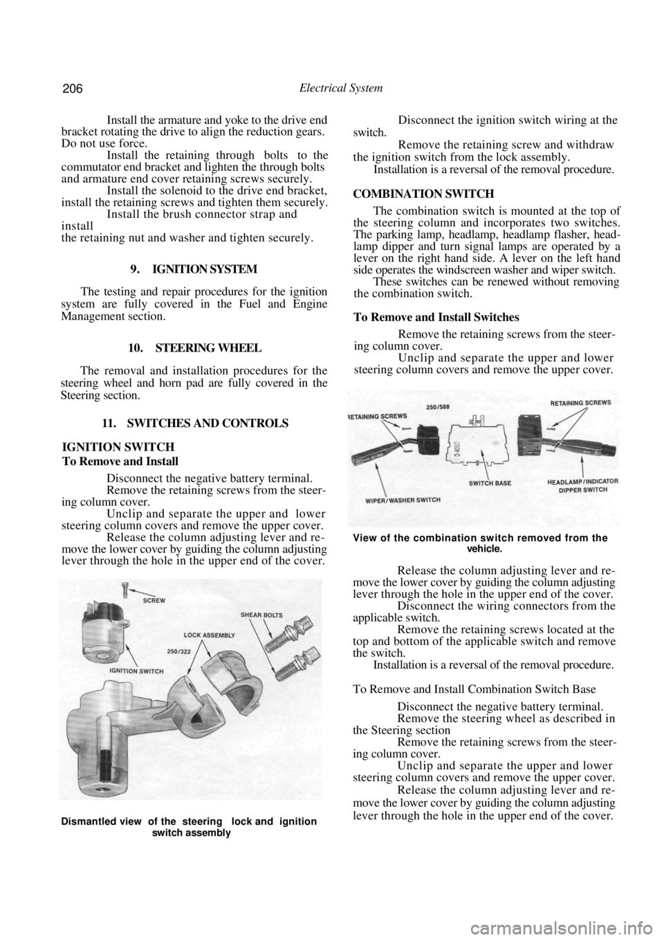
View of the combination switch removed from the
vehicle.
Release the column adjusting lever and re-
move the lower cover by guiding the column adjusting
lever through the hole in the upper end of the cover. Disconnect the wiring connectors from the
applicable switch. Remove the retaining screws located at the
top and bottom of the applicable switch and remove
the switch. Installation is a reversal of the removal procedure.
To Remove and Install Combination Switch Base
Disconnect the negative battery terminal.
Remove the steering wheel as described in
the Steering section Remove the retaining screws from the steer-
ing column cover. Unclip and separate the upper and lower
steering column covers and remove the upper cover.
Release the column adjusting lever and re-
move the lower cover by guiding the column adjusting
lever through the hole in the upper end of the cover.
Dismantled view of the steering lock and ignition
switch assembly
Page 215 of 238
Electrical System 215
Ensure that the wiper motor is in the Park
position before installing the wiper arm. If in doubt,
turn the wiper switch to the Off position and turn the
ignition switch to the On position until the wiper
motor stops.
Install the wiper arm to the pivot so that the
wiper blade is horizontal to the lower edge of the edge
of the rear window when in the Park position.
17. FUSES, FUSIBLE LINKS AND RELAYS
TO CHECK AND RENEW FUSE
NOTE: If a fuse is found to be faulty or
burnt out, use a replacement fuse of the
specified amperage only. The specified amp-
erage is marked on the fuse.
The use of a higher amperage fuse than
that specified could cause damage to the
vehicle wiring harness.
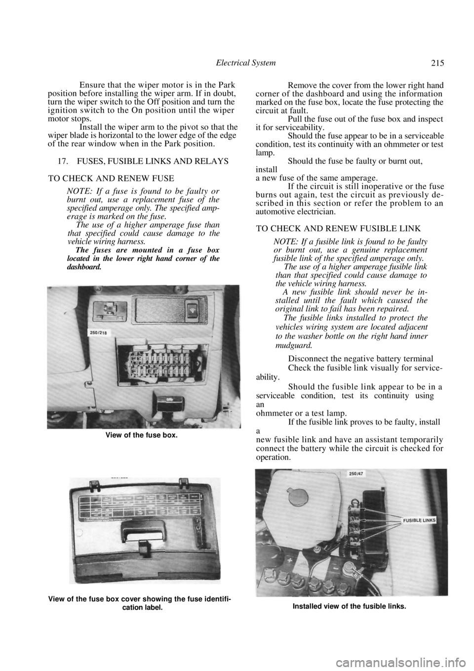
The fuses are mounted in a fuse box
located in the lower right hand corner of the
dashboard.
Remove the cover from the lower right hand
corner of the dashboard and using the information
marked on the fuse box, locate the fuse protecting the
circuit at fault. Pull the fuse out of the fuse box and inspect
it for serviceability.
Should the fuse appear to be in a serviceable
condition, test its continuity with an ohmmeter or test
lamp. Should the fuse be faulty or burnt out,
install
a new fuse of the same amperage. If the circuit is still inoperative or the fuse
burns out again, test the circuit as previously de-
scribed in this section or refer the problem to an
automotive electrician.
TO CHECK AND RENEW FUSIBLE LINK
NOTE: If a fusible link is found to be faulty
or burnt out, use a genuine replacement
fusible link of the specified amperage only.
The use of a higher amperage fusible link
than that specified could cause damage to
the vehicle wiring harness.
A new fusible link should never be in-
stalled until the fault which caused the
original link to fail has been repaired.
The fusible links installed to protect the
vehicles wiring system are located adjacent
to the washer bottle on the right hand inner
mudguard.
Disconnect the negative battery terminal
Check the fusible link visually for service-
ability.
Should the fusible link appear to be in a
serviceable condition, test its continuity using
an
ohmmeter or a test lamp. If the fusible link proves to be faulty, install
a
new fusible link and have an assistant temporarily
connect the battery while the circuit is checked for
operation.
View of the fuse box cover showing the fuse identifi-
cation label. Installed view of the fusible links.
View of the fuse box.
Page 216 of 238
216 Electrical System
NOTE: While checking the operation of the
fusible link, loosely connect the battery-
terminal only, to safeguard against damage
to the wiring harness.
(5) If the circuit is still inoperative or the fusible
link burns out again, refer the problem to an auto-
motive electrician.
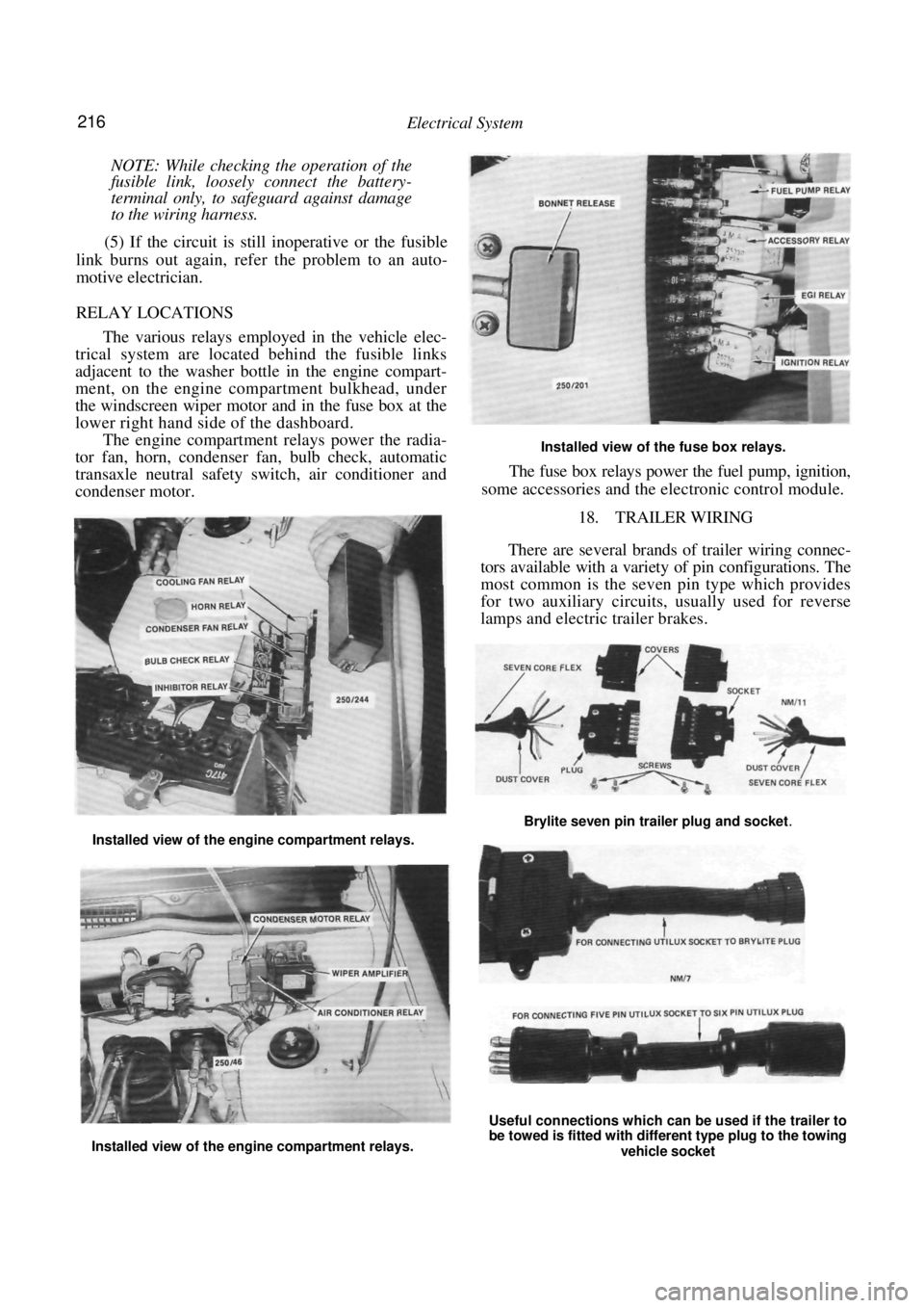
RELAY LOCATIONS
The various relays employed in the vehicle elec-
trical system are located behind the fusible links
adjacent to the washer bottle in the engine compart-
ment, on the engine compartment bulkhead, under
the windscreen wiper motor and in the fuse box at the
lower right hand side of the dashboard.
The engine compartment relays power the radia-
tor fan, horn, condenser fan, bulb check, automatic
transaxle neutral safety switch, air conditioner and
condenser motor.
Installed view of the fuse box relays.
The fuse box relays power the fuel pump, ignition,
some accessories and the el ectronic control module.
18. TRAILER WIRING
There are several brands of trailer wiring connec-
tors available with a variet y of pin configurations. The
most common is the seven pin type which provides
for two auxiliary circuits, usually used for reverse
lamps and electric trailer brakes.
Installed view of the engine compartment relays.
Installed view of the engine compartment relays.
Useful connections which can be used if the trailer to
be towed is fitted with different type plug to the towing
vehicle socket
Brylite seven pin trailer plug and socket.
Page 219 of 238
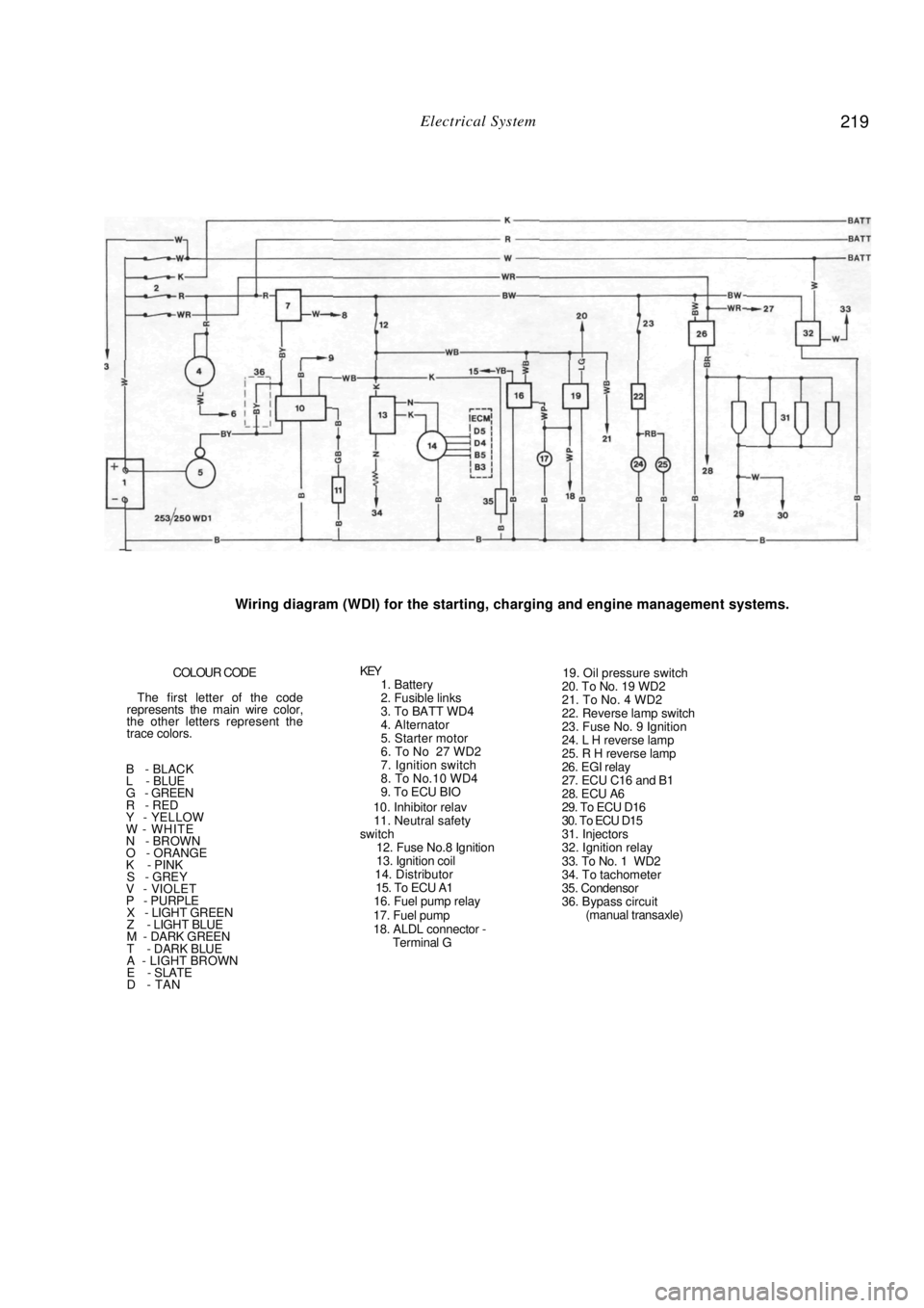
Electrical System 219
Wiring diagram (WDI) for the starting, charging and engine management systems.
COLOUR CODE
The first letter of the code
represents the main wire color,
the other letters represent the
trace colors.
B - BLACK
L - BLUE
G - GREEN
R - RED
Y - YELLOW
W - WHITE
N - BROWN
O - ORANGE
K - PINK
S - GREY V - VIOLET
P - PURPLE X - LIGHT GREEN
Z - LIGHT BLUE
M - DARK GREEN
T - DARK BLUE
A - LIGHT BROWN
E - SLATE
D - TAN
KEY 1. Battery
2. Fusible links
3. To BATT WD4
4. Alternator
5. Starter motor
6. To No 27 WD2
7. Ignition switch
8. To No.10 WD4
9. To ECU BIO
10. Inhibitor relav
11. Neutral safety
switch
12. Fuse No.8 Ignition
13. Ignition coil
14. Distributor
15. To ECU A1
16. Fuel pump relay
17. Fuel pump
18. ALDL connector - Terminal G
19. Oil pressure switch
20. To No. 19 WD2
21. To No. 4 WD2
22. Reverse lamp switch
23. Fuse No. 9 Ignition
24. L H reverse lamp
25. R H reverse lamp
26. EGI relay
27. ECU C16 and B1
28. ECU A6
29. To ECU D16
30. To ECU D15
31. Injectors
32. Ignition relay
33. To No. 1 WD2
34. To tachometer
35. Condensor
36. Bypass circuit (manual transaxle)
Page 220 of 238
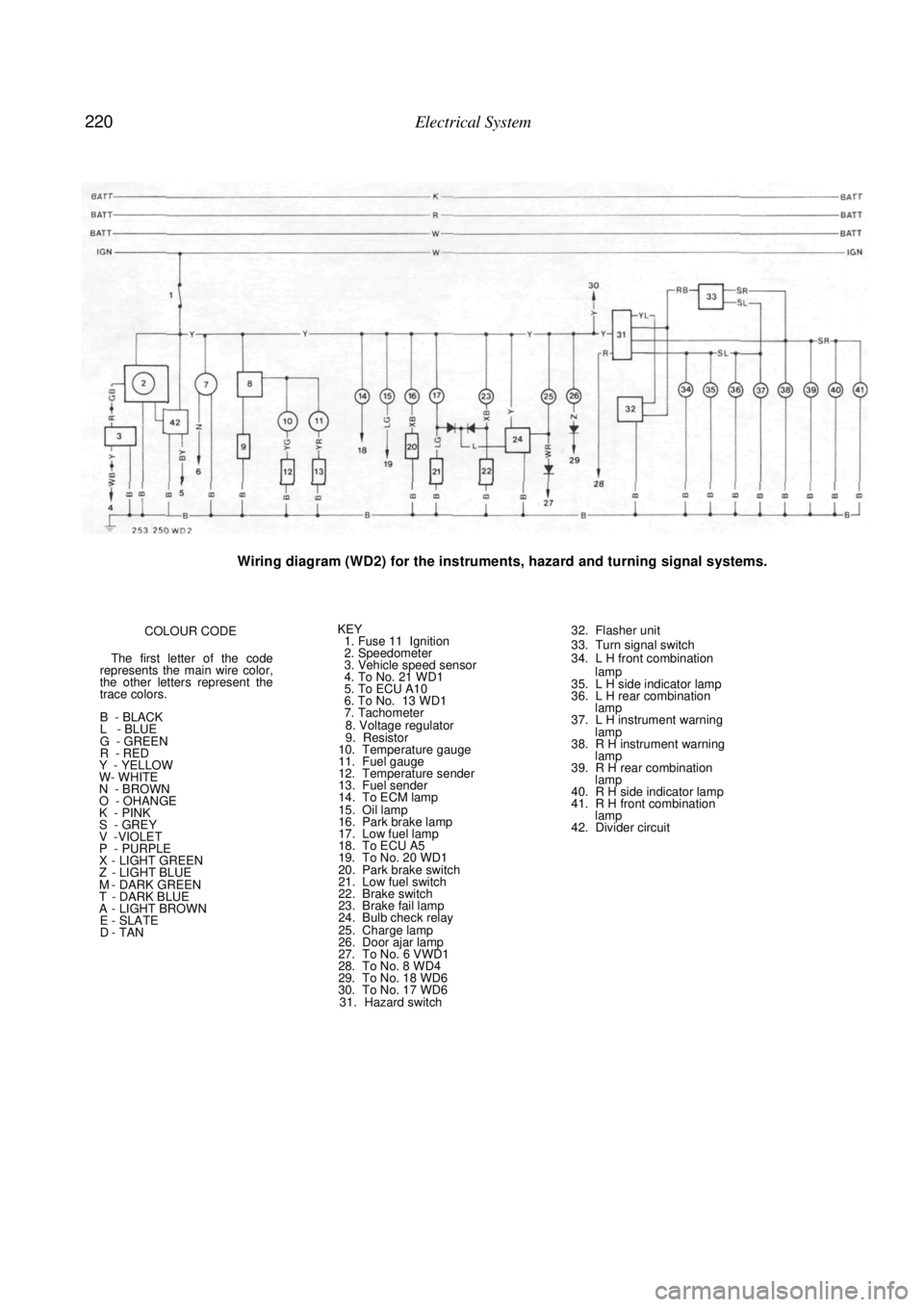
220 Electrical System
Wiring diagram (WD2) for the instruments, hazard and turning signal systems.
COLOUR CODE
The first letter of the code
represents the main wire color,
the other letters represent the
trace colors.
B - BLACK
L - BLUE
G - GREEN
R - RED
Y - YELLOW
W- WHITE
N - BROWN
O - OHANGE
K - PINK
S - GREY V -VIOLET
P - PURPLE X - LIGHT GREEN Z - LIGHT BLUE M - DARK GREEN T - DARK BLUE A - LIGHT BROWN E - SLATE D - TAN
KEY 1. Fuse 11 Ignition
2. Speedometer
3. Vehicle speed sensor
4. To No. 21 WD1
5. To ECU A10
6. To No. 13 WD1
7. Tachometer
8. Voltage regulator
9. Resistor
10. Temperature gauge
11. Fuel gauge
12. Temperature sender
13. Fuel sender
14. To ECM lamp
15. Oil lamp
16. Park brake lamp
17. Low fuel lamp
18. To ECU A5
19. To No. 20 WD1
20. Park brake switch
21. Low fuel switch
22. Brake switch
23. Brake fail lamp
24. Bulb check relay
25. Charge lamp
26. Door ajar lamp
27. To No. 6 VWD1
28. To No. 8 WD4
29. To No. 18 WD6
30. To No. 17 WD6 31. Hazard switch
32. Flasher unit
33. Turn signal switch
34. L H front combination
lamp
35. L H side indicator lamp
36. L H rear combination lamp
37. L H instrument warning
lamp
38. R H instrument warning lamp
39. R H rear combination lamp
40. R H side indicator lamp
41. R H front combination lamp
42. Divider circuit
Page 221 of 238
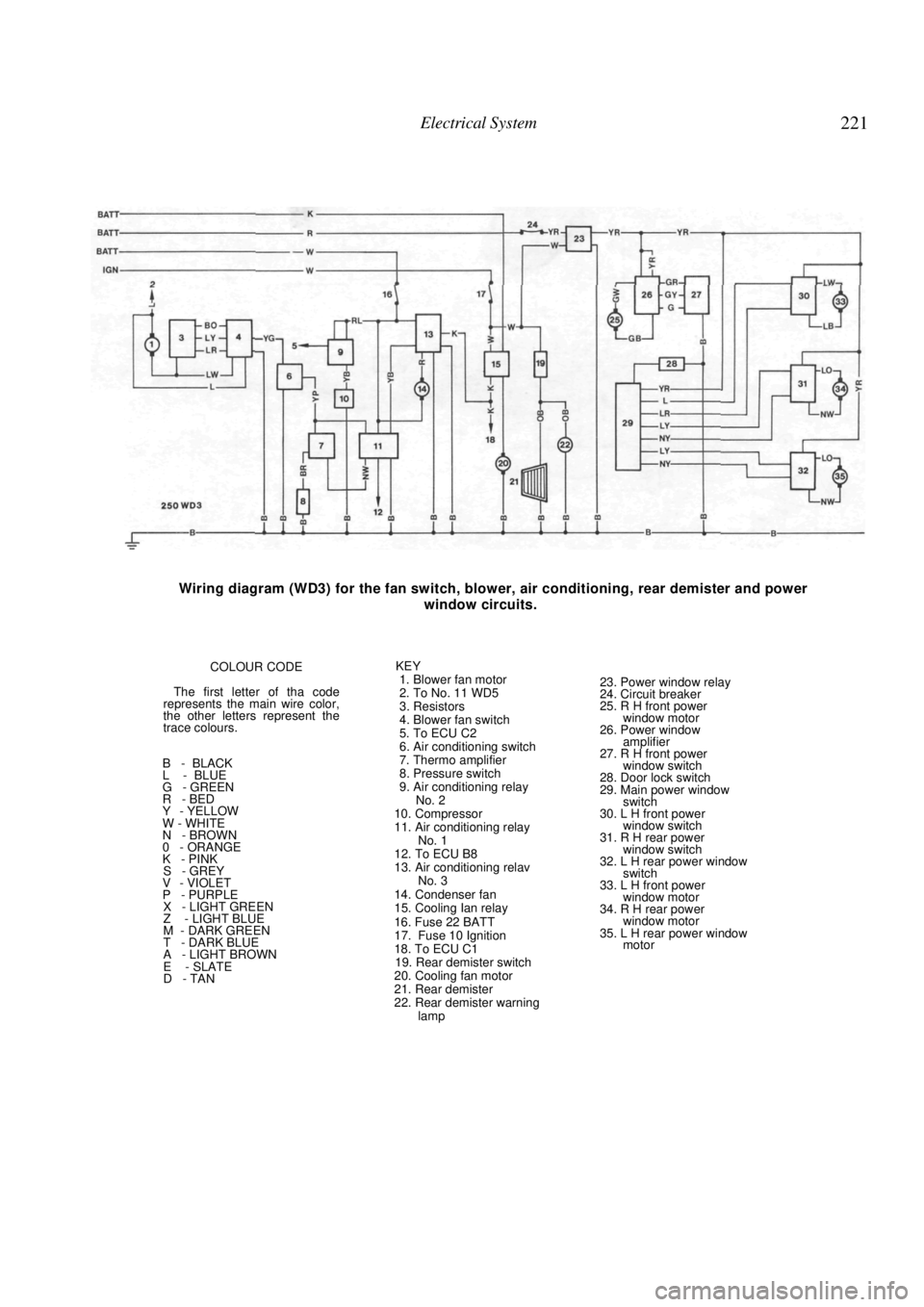
Electrical System 221
Wiring diagram (WD3) for the fan switch, blower, air conditioning, rear demister and power
window circuits.
COLOUR CODE
The first letter of tha code
represents the main wire color,
the other letters represent the
trace colours.
B - BLACK
L - BLUE
G - GREEN
R - BED
Y - YELLOW
W - WHITE
N - BROWN
0 - ORANGE
K - PINK
S - GREY
V - VIOLET
P - PURPLE
X - LIGHT GREEN
Z - LIGHT BLUE
M - DARK GREEN
T - DARK BLUE
A - LIGHT BROWN
E - SLATE
D - TAN KEY
1. Blower fan motor
2. To No. 11 WD5
3. Resistors
4. Blower fan switch
5. To ECU C2
6. Air conditioning switch
7. Thermo amplifier
8. Pressure switch
9. Air conditioning relay No. 2
10. Compressor
11. Air conditioning relay No. 1
12. To ECU B8
13. Air conditioning relav No. 3
14. Condenser fan
15. Cooling Ian relay
16. Fuse 22 BATT
17. Fuse 10 Ignition
18. To ECU C1
19. Rear demister switch
20. Cooling fan motor
21. Rear demister
22. Rear demister warning lamp
23. Power window relay
24. Circuit breaker
25. R H front power
window motor
26. Power window amplifier
27. R H front power window switch
28. Door lock switch
29. Main power window switch
30. L H front power
window switch
31. R H rear power window switch
32. L H rear power window switch
33. L H front power
window motor
34. R H rear power window motor
35. L H rear power window motor