ignition NISSAN PULSAR 1987 User Guide
[x] Cancel search | Manufacturer: NISSAN, Model Year: 1987, Model line: PULSAR, Model: NISSAN PULSAR 1987Pages: 238, PDF Size: 28.91 MB
Page 34 of 238
Roadside Trouble Shooting
ing the wiring from any component, ensure
that the ignition switch is off and the
negative battery terminal is disconnected to
prevent damage to the solid state circuitry.
(4) Open the electrode gap of a serviceable spark
plug to 6 mm. Securely earth the plug using a jumper
lead or by tying the plug to an earthed engine
component.
(5) Disconnect the high tension lead from a
spark plug and connect it to the test spark plug.
(6) Have an assistant operate the starter motor.
(7) Check that a spark, if any, jumps the gap on
the test spark plug. If the spark is satisfactory, proceed to operation
(8).
If there is no spark, proceed as follows:
(a) Check the high tension leads to ensure that
they are dry and that the insulation is not cracked or
perished. Check the ends of the leads for burning. Using an ohmmeter, measure the resistance in
each high tension lead. The resistance should be no
more than 15 000 ohms per lead.
(b) Check the distributor cap to ensure that it is
dry and clean. Examine both the inside and outside of
the cap for cracks or tracki ng, particularly between the
high tension lead segments.
Check that the carbon brush in the centre of the
distributor cap interior fa ce is clean and dry and
ensure that the brush moves freely in and out of its
locating hole.
(c) Check the rotor arm for cracks, deposits and
burning on the metal arm. (d) Ensure that the high tension leads have dry.
clean and secure connections on the distributor cap. (8) If the above checks r esult in a good spark at
the spark plug high tension leads but the engine is still
not operating satisfac torily, remove all the spark plugs
and check the condition and electrode gap as de-
scribed in the Engine Tune-up section under the
appropriate heading.
3. TO CHECK FUEL SYSTEM
Due to the complex nature of the EFI system, it is
recommended that should the following checks prove
satisfactory but the engine fail to start, reference be
made to the Fuel and Engine Management section of
this manual or a Nissan workshop be consulted.
(1) Check that the fuel tank contains a reason-
able amount of fuel. (2) Have an assistant switch the ignition on and
off while squeezing the fuel supply hose with the
fingers. If the fuel pump is operating it should be
possible to feel the fuel pr essure increase for approx-
imately two seconds.
NOTE: When conducting the above test it
should be possible to hear the fuel pump and
ignition relays clicking when the ignition is
switched on and off
If the fuel pump relay fails, power will be
supplied to the fuel pump via the oil pressure
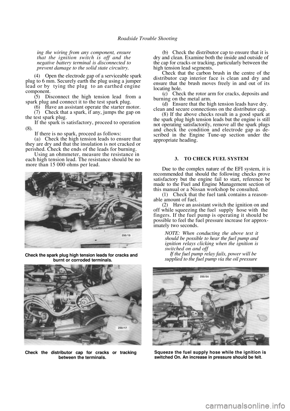
Check the distributor cap for cracks or tracking between the terminals. Squeeze the fuel supply hose while the ignition is
switched On. An increase in pressure should be felt.
Check the spark plug high tension leads for cracks and
burnt or corroded terminals.
Page 35 of 238
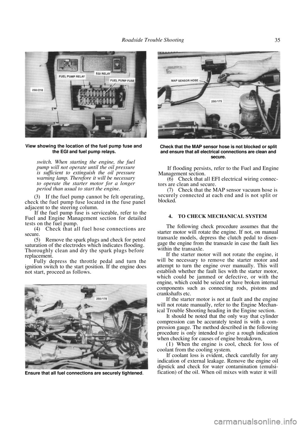
Roadside Trouble Shooting 35
View showing the location of the fuel pump fuse and the EGI and fuel pump relays.
switch. When starting the engine, the fuel
pump will not operate until the oil pressure
is sufficient to extinguish the oil pressure
warning lamp. Therefore it will be necessary
to operate the starter motor for a longer
period than usual to start the engine.
(3) If the fuel pump cannot be felt operating,
check the fuel pump fuse located in the fuse panel
adjacent to the steering column.
If the fuel pump fuse is serviceable, refer to the
Fuel and Engine Management section for detailed
tests on the fuel pump.
(4) Check that all fuel hose connections are
secure.
(5) Remove the spark plugs and check for petrol
saturation of the electrodes which indicates flooding.
Thoroughly clean and dry the spark plugs before
replacement. Fully depress the throttle pedal and turn the
ignition switch to the start position. If the engine does
not start, proceed as follows.
Check that the MAP sensor hose is not blocked or split
and ensure that all electrical connections are clean and
secure.
If flooding persists, refer to the Fuel and Engine
Management section.
(6) Check that all EFI electrical wiring connec-
tors are clean and secure.
(7) Check that the MAP sensor vacuum hose is
securely connected at each end and is not split or
blocked.
4. TO CHECK MECHANICAL SYSTEM
The following check procedure assumes that the
starter motor will rotate the engine. If not, on manual
transaxle models, depress the clutch pedal to disen-
gage the engine from the tr ansaxle in case the fault lies
within the transaxle.
If the starter motor will not rotate the engine, it
will be necessary to remove the starter motor and
attempt to turn the engine over manually. This will
establish whether the fault lies with the starter motor,
which could be jammed or defective, or with the
engine, which could be seized or have broken internal
components such as connecting rods, pistons and
crankshafts etc.
If the starter motor is not at fault and the engine
will not rotate manually, refer to the Engine Mechan-
ical Trouble Shooting heading in the Engine section.
It should be noted that the only way that cylinder
compression can be accurately tested is with a com-
pression gauge. The method described in the following
procedure is only intended to give a rough indication
when checking for causes of engine breakdown,
(I) When the engine is cool, check for loss of
coolant from the cooling system.
If coolant loss is evident, check carefully for any
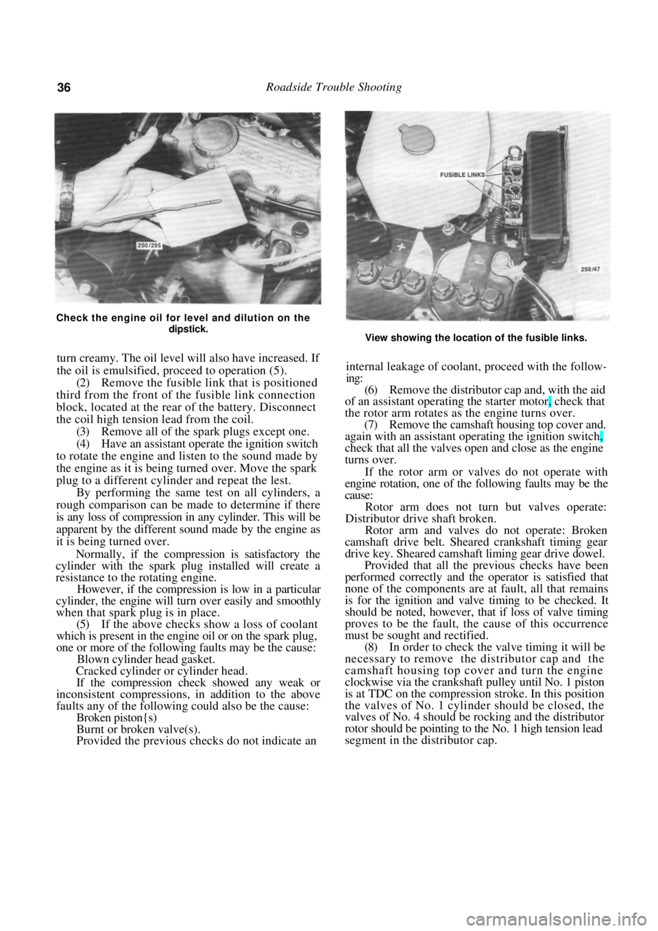
indication of external leakage. Remove the engine oil
dipstick and check for wate r contamination (emulsi-
fication) of the oil. When oil mixes with water it will
Ensure that all fuel connections are securely tightened.
Page 36 of 238
36 Roadside Trouble Shooting
Check the engine oil for level and dilution on the dipstick.
turn creamy. The oil level will also have increased. If
the oil is emulsified, proceed to operation (5).
(2) Remove the fusible link that is positioned
third from the front of th e fusible link connection
block, located at the rear of the battery. Disconnect
the coil high tension lead from the coil. (3) Remove all of the spark plugs except one.
(4) Have an assistant operate the ignition switch
to rotate the engine and listen to the sound made by
the engine as it is being turned over. Move the spark
plug to a different cylinder and repeat the lest. By performing the same test on all cylinders, a
rough comparison can be made to determine if there
is any loss of compression in any cylinder. This will be
apparent by the different sound made by the engine as
it is being turned over.
Normally, if the compression is satisfactory the
cylinder with the spark plug installed will create a
resistance to the rotating engine.
However, if the compression is low in a particular
cylinder, the engine will tu rn over easily and smoothly
when that spark plug is in place.
(5) If the above checks show a loss of coolant
which is present in the engine oil or on the spark plug,
one or more of the following faults may be the cause:
Blown cylinder head gasket.
Cracked cylinder or cylinder head.
If the compression check showed any weak or
inconsistent compressions, in addition to the above
faults any of the following could also be the cause:
Broken piston{s)
Burnt or broken valve(s).
Provided the previous checks do not indicate an
View showing the location of the fusible links.
internal leakage of coolant, proceed with the follow-
ing:
(6) Remove the distributor cap and, with the aid
of an assistant operating th e starter motor, check that
the rotor arm rotates as the engine turns over. (7) Remove the camshaft hous ing top cover and.
again with an assistant operating the ignition switch,
check that all the valves open and close as the engine
turns over.
If the rotor arm or valves do not operate with
engine rotation, one of the following faults may be the
cause:
Rotor arm does not turn but valves operate:
Distributor drive shaft broken.
Rotor arm and valves do not operate: Broken
camshaft drive belt. Sheare d crankshaft timing gear
drive key. Sheared camshaft liming gear drive dowel.
Provided that all the previous checks have been
performed correctly and the operator is satisfied that
none of the components are at fault, all that remains
is for the ignition and valve timing to be checked. It
should be noted, however, that if loss of valve timing
proves to be the fault, th e cause of this occurrence
must be sought and rectified.
(8) In order to check the valve timing it will be
necessary to remove the distributor cap and the
camshaft housing top cover and turn the engine
clockwise via the crankshaft pulley until No. 1 piston
is at TDC on the compression stroke. In this position
the valves of No. 1 cylinder should be closed, the
valves of No. 4 should be rocking and the distributor
rotor should be pointing to the No. 1 high tension lead
segment in the distributor cap.
Page 40 of 238
40 Engine
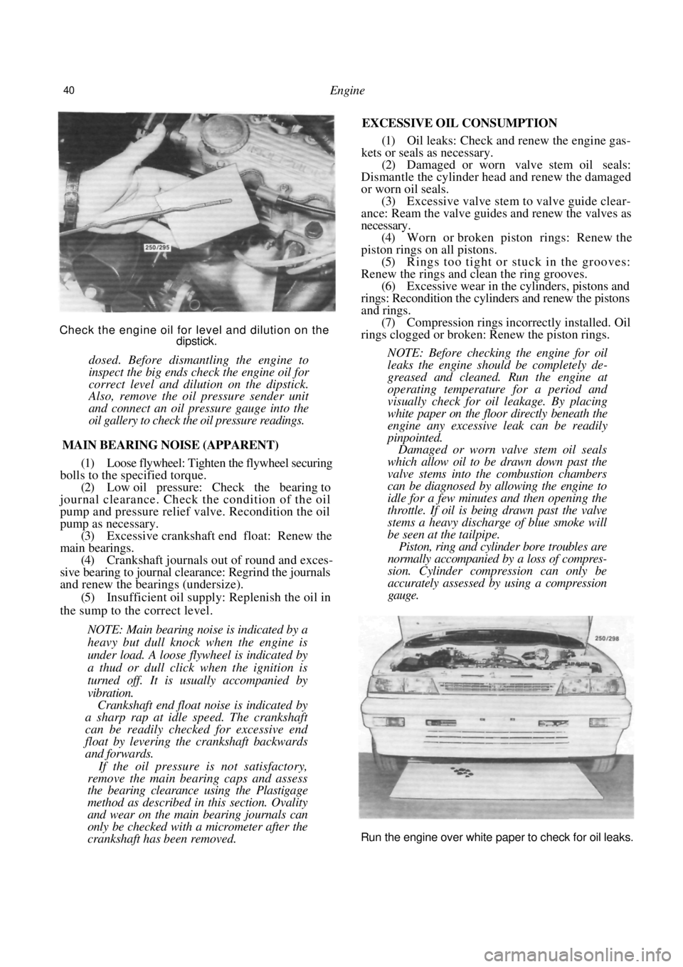
Check the engine oil for level and dilution on the dipstick.
dosed. Before dismantling the engine to
inspect the big ends check the engine oil for
correct level and dilution on the dipstick.
Also, remove the oil pressure sender unit
and connect an oil pressure gauge into the
oil gallery to check the oil pressure readings.
MAIN BEARING NOISE (APPARENT)
(1) Loose flywheel: Tighten the flywheel securing
bolls to the specified torque. (2) Low oil pressure: Check the bearing to
journal clearance. Check the condition of the oil
pump and pressure relief valve. Recondition the oil
pump as necessary. (3) Excessive crankshaft end float: Renew the
main bearings. (4) Crankshaft journals out of round and exces-
sive bearing to journal clear ance: Regrind the journals
and renew the bearings (undersize).
(5) Insufficient oil supply: Replenish the oil in
the sump to the correct level.
NOTE: Main bearing noise is indicated by a
heavy but dull knock when the engine is
under load. A loose flywheel is indicated by
a thud or dull click when the ignition is
turned off. It is us ually accompanied by
vibration.
Crankshaft end float noise is indicated by
a sharp rap at idle speed. The crankshaft
can be readily checked for excessive end
float by levering the crankshaft backwards
and forwards.
If the oil pressure is not satisfactory,
remove the main bearing caps and assess
the bearing clearance using the Plastigage
method as described in this section. Ovality
and wear on the main bearing journals can
only be checked with a micrometer after the
crankshaft has been removed.
EXCESSIVE OIL CONSUMPTION
(1) Oil leaks: Check and renew the engine gas-
kets or seals as necessary.
(2) Damaged or worn valve stem oil seals:
Dismantle the cylinder head and renew the damaged
or worn oil seals. (3) Excessive valve stem to valve guide clear-
ance: Ream the valve guides and renew the valves as
necessary. (4) Worn or broken piston rings: Renew the
piston rings on all pistons. (5) Rings too tight or stuck in the grooves:
Renew the rings and clean the ring grooves.
(6) Excessive wear in the cylinders, pistons and
rings: Recondition the cylinders and renew the pistons
and rings. (7) Compression rings incorrectly installed. Oil
rings clogged or broken: Renew the piston rings.
NOTE: Before checking the engine for oil
leaks the engine should be completely de-
greased and cleaned. Run the engine at
operating temperature for a period and
visually check for oil leakage. By placing
white paper on the floor directly beneath the
engine any excessive leak can be readily
pinpointed.
Damaged or worn valve stem oil seals
which allow oil to be drawn down past the
valve stems into the combustion chambers
can be diagnosed by allowing the engine to
idle for a few minutes and then opening the
throttle. If oil is being drawn past the valve
stems a heavy discharge of blue smoke will
be seen at the tailpipe.
Piston, ring and cylinder bore troubles are
normally accompanied by a loss of compres-
sion. Cylinder compression can only be
accurately assessed by using a compression
gauge.
Run the engine over white paper to check for oil leaks.
Page 52 of 238

52 Engine
leaks and rectify as necessary. Check and if necessary
adjust the ignition timing as described in the Engine
Tune-up section.
(16) When the engine has reached normal oper-
ating temperature, tighten the cylinder head bolts
another 40-50 degrees in the correct sequence shown
in the illustration, ensuring that the tension does not
exceed 135 Nm.
TO DISMANTLE
(1) Remove the cylinder head as previously
described.
(2) Remove the thermostat housing and sealing
ring from the cylinder head.
(3) Remove the nuts securing the inlet and
exhaust manifolds to the cylinder head and remove
the manifolds. Discard the gaskets. (4) Lift the rocker arm and thrust pad from the
top of each valve assembly, keeping them in order for
assembly to their or iginal locations.
(5) Slide each hydraulic tappet from its bore in
the cylinder head, also keeping them in order for
assembly to their or iginal locations.
(6) Before removing the valves the deposits in
Installed view of the cylinder head oil pressure relief
valve.
the combustion chambers s hould be removed. Care
should be taken not to damage the cylinder head
gasket face.
(7) Using a valve spring compressor, compress
each spring in turn. Remove the split retaining collets
and slowly release the compressor.
(8) Remove the valve spring retainers and valve
springs. (9) Remove the valve stem seals from the top of
the valve guides and detach the exhaust valve rotators
and the inlet valve spring seats, from the cylinder
head. (10) Remove any burrs from the valve stem
grooves to prevent damage to the valve guides when
the valves are removed from the cylinder head. (11) Remove the valves, keeping them in order
for assembly to their original locations.
NOTE: To keep the valve assemblies in
order have a rack numbered from 1 to 8 and
instill the components in this rack, starting
from the front of the cylinder head.
(12) If the oil pressure relief valve in the cylinder
head is to be renewed, proceed as follows:
(a) Using a drift, remove the welch plug from
the distributor end of the cylinder head. (b) Remove the recessed screw from the thermo-
stat housing end of the cylinder head. (c) Using a long brass drift inserted in the oilway
through the tappet bores from the thermostat housing
end. remove the oil pressure relief valve from the
cylinder head. Discard the relief valve.
TO CLEAN AND INSPECT
(1) Clean the valves thoroughly and discard any
burnt, warped or cracked valves. (2) Have the valves refaced to the recommended
angle on a valve refacing machine. The valve stem tips
are specially hardened and should not be refaced.
Dismantled view of the valve and spring components.
Page 69 of 238
Cooling and Heating Systems 69
the cylinder head or cylinder block and renew the
cylinder head gasket.
(2) Crack in the cylinder head or cylinder block:
Repair or renew as necessary.
NOTE; Check the engine for internal leak-
age by withdrawing the dipstick and inspect-
ing for emulsified oil. Run the engine and
check for excessive steam at the exhaust
pipe which would indi cate coolant leakage
into the combustion chamber.
COOLANT LOSS BY OVERFLOW
(1) Overfull system: Drain the excess coolant
from the system.
(2) Faulty radiator cap: Renew the faulty cap.
(3) Blocked radiator core tubes: Clean or renew
the radiator core.
(4) Faulty thermostat: Renew the thermostat.
(5) Coolant foaming due to poor quality anti-
freeze or corrosion inhibitor: Drain the system and
renew the coolant and additive.
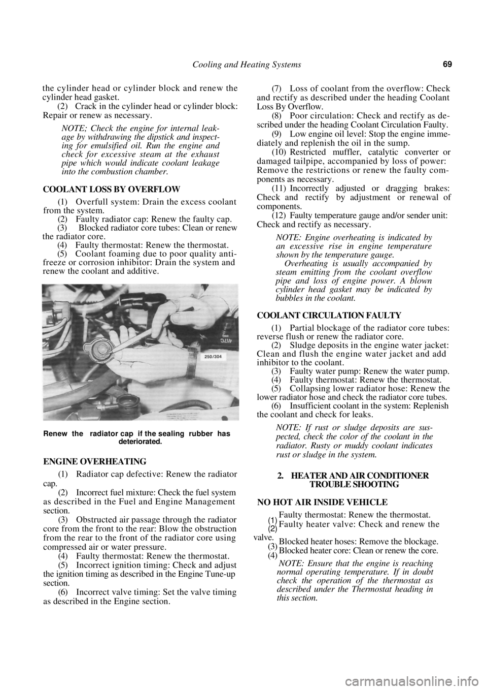
Renew the radiator cap if the sealing rubber has
deteriorated.
ENGINE OVERHEATING
(1) Radiator cap defective: Renew the radiator
cap.
(2) Incorrect fuel mixture: Check the fuel system
as described in the Fuel and Engine Management
section. (3) Obstructed air passage through the radiator
core from the front to the rear: Blow the obstruction
from the rear to the front of the radiator core using
compressed air or water pressure. (4) Faulty thermostat: Renew the thermostat.
(5) Incorrect ignition timing: Check and adjust
the ignition timing as described in the Engine Tune-up
section. (6) Incorrect valve timing: Set the valve timing
as described in th e Engine section.
(7) Loss of coolant from the overflow: Check
and rectify as described under the heading Coolant
Loss By Overflow.
(8) Poor circulation: Check and rectify as de-
scribed under the heading Coolant Circulation Faulty.
(9) Low engine oil level: Stop the engine imme-
diately and replenish the oil in the sump. (10) Restricted muffler, catalytic converter or
damaged tailpipe, accompanied by loss of power:
Remove the restrictions or renew the faulty com-
ponents as necessary.
(11) Incorrectly adjusted or dragging brakes:
Check and rectify by adjustment or renewal of
components. (12) Faulty temperature gauge and/or sender unit:
Check and rectify as necessary.
NOTE: Engine overheating is indicated by
an excessive rise in engine temperature
shown by the temperature gauge.
Overheating is usually accompanied by
steam emitting from the coolant overflow
pipe and loss of engine power. A blown
cylinder head gasket may be indicated by
bubbles in the coolant.
COOLANT CIRCULATION FAULTY
(1) Partial blockage of the radiator core tubes:
reverse flush or renew the radiator core.
(2) Sludge deposits in the engine water jacket:
Clean and flush the engine water jacket and add
inhibitor to the coolant. (3) Faulty water pump: Renew the water pump.
(4) Faulty thermostat: Renew the thermostat.
(5) Collapsing lower radiator hose: Renew the
lower radiator hose and check the radiator core tubes. (6) Insufficient coolant in the system: Replenish
the coolant and check for leaks.
NOTE: If rust or sludge deposits are sus-
pected, check the color of the coolant in the
radiator. Rusty or muddy coolant indicates
rust or sludge in the system.
2. HEATER AND AIR CONDITIONER TROUBLE SHOOTING
NO HOT AIR INSIDE VEHICLE
Faulty thermostat: Renew the thermostat.
Faulty heater valve: Check and renew the
Blocked heater hoses: Remove the blockage.
Blocked heater core: Clean or renew the core.
NOTE: Ensure that the engine is reaching
normal operating temperature. If in doubt
check the operation of the thermostat as
described under the Thermostat heading in
this section.
(1)
(2)
valve.
(3)
(4)
Page 73 of 238
Cooling and Heating Systems 73
(1) Renew all hoses that show signs of cracking
or perishing.
(2) Before finally tightening the hose clips, en-
sure that the hoses are push ed fully onto the radiator
and are not kinked. (3) On automatic transaxle models, ensure that
the oil cooler hoses are correctly installed to the
radiator and show no signs of leakage. Check and top
up the automatic transaxle fluid as necessary.
5. COOLING FAN
The radiator cooling fan is controlled by the
electronic control unit, and on vehicles with air
conditioning, the condenser fan relay. On vehicles
with air conditioning there are two cooling fans, one
is larger than the other. The large fan is for the
radiator and the smaller fan provides extra cooling
when the air conditioning is activated. Each fan is
controlled by a separate system.
TO TEST COOLING FAN AND SYSTEM
(1) With the cooling system cold and the air
conditioning, if applicable, switched off, switch the
ignition On and confirm that the cooling fan is
stationary.
NOTE: Leave the ignition On for all tests
unless otherwise stated.
(2) In the above test, if the cooling fan rotates,
proceed as follows:
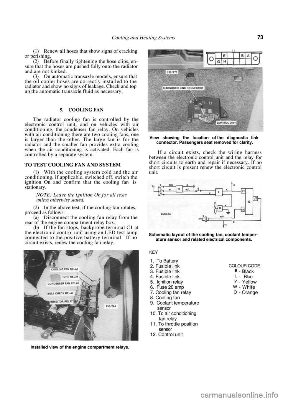
(a) Disconnect the cooling fan relay from the
rear of the engine compartment relay box.
(b) If the fan stops, backprobe terminal C1 at
the electronic control unit using an LED test lamp
connected to the positive battery terminal. If no
circuit exists, renew the cooling fan relay.
View showing the location of the diagnostic link
connector. Passengers seat removed for clarity.
If a circuit exists, check the wiring harness
between the electronic control unit and the relay for
short circuits to earth and repair if necessary. If no
short circuit is present renew the electronic control
unit.
Schematic layout of the cooling fan, coolant temper-
ature sensor and related electrical components.
Installed view of the engine compartment relays. KEY
1. To Battery
2. Fusible link
COLOUR CODE
3. Fusible link
B-Black
4. Fusible linkL- Blue
5. I
gnition relayY- Yellow
6. Fuse 20 am
pW-White
7. Coolin
g fan relayO-Orange
8. Coolin
g fan
9. Coolant tem
perature
sensor
10. To air conditionin
g
fan rela
y
11. To throttle
position
sensor
12. Control unit
Page 74 of 238
74 Cooling and Heating Systems
NOTE: Refer to the Fuel and Engine Man-
agement section for the correct procedure for
backprobing the control unit.
(3) In operation (1) if the cooling fan is station-
ary proceed as follows:
(a) Connect a jumper lead between the terminals
A and B of the diagnostic link connector. (b) if the fan runs, the fan circuit is satisfactory.
If the engine is overheating check the coolant temper-
ature sensor as described in the Fuel and Engine
Management section under the appropriate codes. (c) If the fan does not run, check the fuse (6) and
the fusible link (4) show n on the illustration.
(d) Backprobe terminal C1 at the electronic
control unit using an LED t est lamp connected to the
positive battery terminal. If no circuit exists, renew
the electronic control unit. (e) If the fuse and fusible links are serviceable,
ensure that power is available at the white and pink
wires from the fuse and fusible link of the cooling fan
relay. Repair any faults in the wiring to that point if
necessary. (f) Switch the ignition Off. disconnect the
cooling fan wiring connector at the radiator and
connect power to the fan. Renew the fan if it does not
run.
(4) On air conditioned models, remove the
jumper lead from the ALDL connector if still in-
stalled, start the engine and allow it to idle. Switch the
air conditioning on and ensu re that the cooling fan
runs.
If the cooling fan is opera ting as described above
but cooling system problems still exist, refer to the
Trouble Shooting heading at the start of this section.
TO REMOVE AND INSTAL COOLING FAN
(1) Disconnect the negative battery terminal.
(2) Disconnect the cooling fa n and, if applicable,
the air conditioning fan wiring connectors at the
upper edge of the radiator. (3) On models with air conditioning, remove the
compressor hose bracket bolt from the centre of the
radiator support panel.
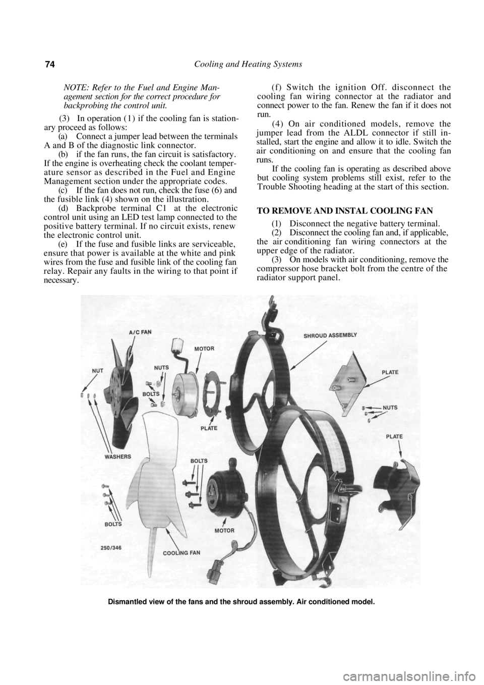
Dismantled view of the fans and the shroud assembly. Air conditioned model.
Page 82 of 238

82
FUEL AND ENGINE MANAGEMENT
CAUTION: To prevent severe electrical shock, extreme care must be taken when
working on or near the electronic ignition system as dangerous high tension voltages
are produced in both the primary and secondary circuits. See the text fo\
r
precautionary notes.
SPECIFICATIONS
FUEL INJECTION
Type:
1.6 liter engine .................................. Single point
1.8 liter engine................................... Multi point
FUEL PUMP
Type ................................................................ Electric
Pressure at idle:
1.6 liter engine ..................................... 62-90 kPa
1.8 liter engine ................................ 190-230 kPa
FUEL FILTER
Type ................................................ Inline, disposable
AIR FILTER
Type ................................... Disposable paper element
DISTRIBUTOR
Make ........................................................ Delco Remy
Advance contro l .......................................... Electronic
Rotation of rotor .................................. Anti-clockwise
Firing order....................................................1 -3-4-2
ADJUSTMENTS
Base idle speed ..................................... 550-650 rpm
Ignition timing.......................................... 10° BTDC
TORQUE WRENCH SETTINGS
Throttle body nuts.......................................... 10 Nm
*Throttle body bolts ........................................ 12 Nm
*Fuel hose fittings............................................ 35 Nm
Fuel rail bolts ....................................................8 Nm
Fuel tank drain plug ........................................ 24 Nm
Coolant temperature sensor ............................ 12 Nm
Oxygen sensor .................................................. 40 Nm
MAT sensor..................................................... 14 Nm
*1.6 liter engine
l . 8 liter engine
1. FUEL AND ENGINE MANAGEMENT
TROUBLE SHOOTING
NOTE: The following Trouble Shooting pro-
cedures are basic checks only. If these pro-
cedures fail to locate the fault, refer to the
System Diagnosis and Adjustments heading
for more thorough testing.
Prior to performing any of the following
operations, refer to the Service Precautions
and Procedures heading.
ENGINE WILL NOT START OR HARD TO
START
(1) Water in the fuel: Dr ain the fuel from the
system and renew the fuel filter.
(2) Fault in the power supply: Check the battery,
fusible links and fuses. Check for clean, secure con-
nections, particularly the earth connections. Check the
EG1 and fuel pump relays.
NOTE: If the fuel pump relay fails, power
will be supplied to the fuel pump via the oil
pressure switch. When starting the engine,
Check that the MAP sensor hose is not blocked or split
and ensure that all electrical connections are clean and
secure.
Page 83 of 238

Fuel and Engine Management 83
the fuel pump will not operate until the oil
pressure is sufficient to extinguish the oil
pressure warning lamp. Therefore it will be
necessary to operate the starter motor for a
longer period than usual to start the engine.
(3) Faulty EFI component wiring connections:
Check that all component wiring connections are
clean and secure.
(4) Manifold absolute pressure (MAP) sensor
vacuum hose blocked or disconnected: Clear or recon-
nect the vacuum hose. (5) Fault in the ignition system: Check the
primary and secondary ignition circuits.
(6) Engine flooded: Fully depress the throttle
pedal until the engine starts. Check the coolant
temperature sensor. Check th e injector(s) for leakage.
ENGINE STARTS THEN STALLS
(1) Water in the fuel: Dr ain the fuel from the
system and renew the fuel filter.
(2) Air leakage at the inlet manifold: Check all
joints and hoses for air leaks. (3) Faulty EFI wiring connections: Check that
all component wiring connections are clean and
secure.
(4) Ignition timing incorrectly set: Check and
adjust the timing. (5) MAP sensor faulty or supply hose discon-
nected or blocked: Check the vacuum supply hose.
Check the operation of the MAP sensor.
ENGINE MISFIRES
(1) Faulty, dirty or incorrectly adjusted spark
plugs: Renew or clean and adjust the spark plugs.
(2) Condensation in the distributor cap: Dry and
examine the cap for cracks. (3) Faulty high tension leads: Check and renew
the high tension leads.
Testing the fuel system pressure using a pressure
gauge.
(4) Faulty ignition coil: Check and renew the
ignition coil.
(5) Fuel blockage: Check for blockage in the fuel
filter, lines and injector(s). (6) Low fuel pressure: Check the fuel pump and
fuel pressure regulator. (7) Water in the fuel: Dr ain the fuel from the
system and renew the fuel filter. (8) Loose fuel supply wiring connectors: Check
all connectors for tightness. (9) Faulty fuel injector: Check the connections
and test the condition of the fuel injectors.
ENGINE LACKS POWER
(1) Ignition timing incorrectly set: Check and
adjust the timing.
(2) Water in the fuel: Dr ain the fuel from the
system and renew the fuel filter.
(3) Incorrectly adjusted throttle cable: Adjust the
throttle cable.
Check the distributor cap for cracks or tracking be- tween the terminals. The air filter element should be renewed at 40 000 km
intervals. 1.8 liter engine.