steering NISSAN PULSAR 1987 Service Manual
[x] Cancel search | Manufacturer: NISSAN, Model Year: 1987, Model line: PULSAR, Model: NISSAN PULSAR 1987Pages: 238, PDF Size: 28.91 MB
Page 179 of 238

Brakes 179
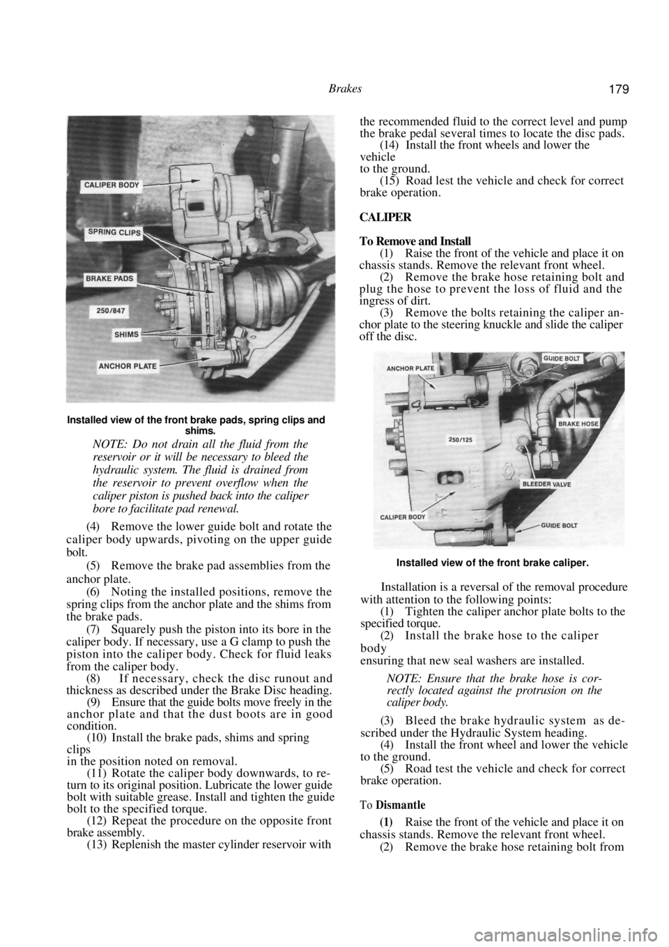
Installed view of the front brake pads, spring clips and shims.
NOTE: Do not drain all the fluid from the
reservoir or it will be necessary to bleed the
hydraulic system. The fluid is drained from
the reservoir to prevent overflow when the
caliper piston is pushed back into the caliper
bore to facilitate pad renewal.
(4) Remove the lower guide bolt and rotate the
caliper body upwards, pivoting on the upper guide
bolt.
(5) Remove the brake pad assemblies from the
anchor plate. (6) Noting the installed positions, remove the
spring clips from the anchor plate and the shims from
the brake pads.
(7) Squarely push the piston into its bore in the
caliper body. If necessary, us e a G clamp to push the
piston into the caliper b ody. Check for fluid leaks
from the calip er body.
(8) If necessary, check the disc runout and
thickness as described under the Brake Disc heading.
(9) Ensure that the guide bolts move freely in the
anchor plate and that the dust boots are in good
condition. (10) Install the brake pads, shims and spring
clips
in the position noted on removal. (11) Rotate the caliper body downwards, to re-
turn to its original position. Lubricate the lower guide
bolt with suitable grease. In stall and tighten the guide
bolt to the specified torque. (12) Repeat the procedure on the opposite front
brake assembly. (13) Replenish the master cylinder reservoir with the recommended fluid to the correct level and pump
the brake pedal several times to locate the disc pads.
(14)
Install the front wheels and lower the
vehicle
to the ground. (15) Road lest the vehicle and check for correct
brake operation.
CALIPER
To Remove and Install
(1) Raise the front of the vehicle and place it on
chassis stands. Remove the relevant front wheel. (2) Remove the brake hose retaining bolt and
plug the hose to prevent the loss of fluid and the
ingress of dirt. (3) Remove the bolts retaining the caliper an-
chor plate to the steering knuckle and slide the caliper
off the disc.
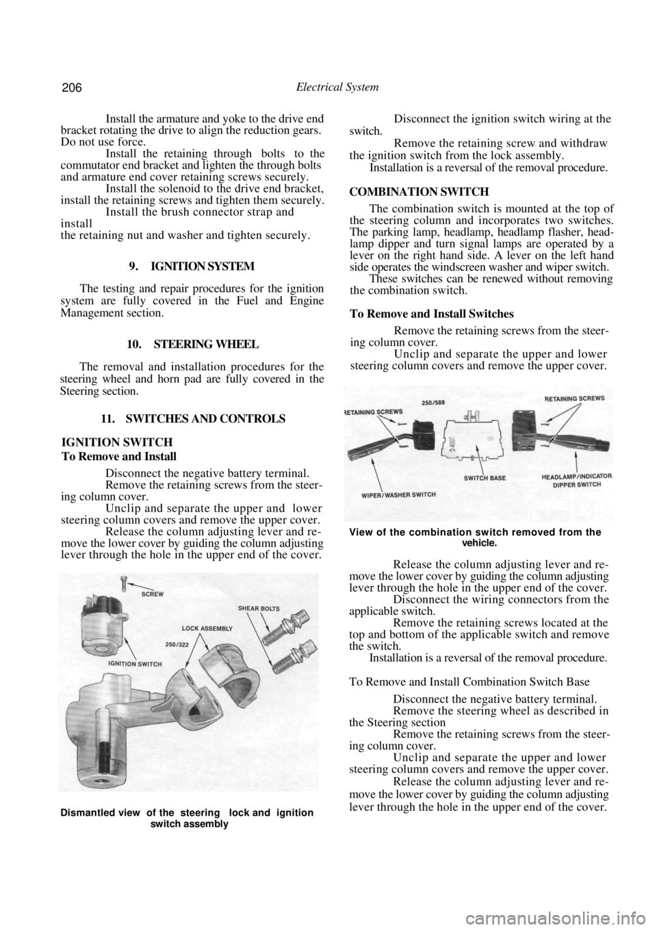
Installed view of the front brake caliper.
Installation is a reversal of the removal procedure
with attention to the following points:
(1) Tighten the caliper anch or plate bolts to the
specified torque.
(2) Install the brake hose to the caliper
body
ensuring that new seal washers are installed.
NOTE: Ensure that the brake hose is cor-
rectly located against the protrusion on the
caliper body.
(3) Bleed the brake hydraulic system as de-
scribed under the Hydraulic System heading. (4) Install the fron t wheel and lower the vehicle
to the ground. (5) Road test the vehicle and check for correct
brake operation.
To Dismantle
(1) Raise the front of the vehicle and place it on
chassis stands. Remove the relevant front wheel.
(2) Remove the brake hose retaining bolt from
Page 181 of 238

Brakes 181
chor plate to the steering knuckle and slide the caliper
off the brake disc. Suspend the caliper clear of the
work area using wire or cord.
(3) Suitably mark the location of the disc in
relation to the hub.
(4) Slide the disc off the hub. If the disc is
difficult to remove, install two M8 x 1.25 mm bolts in
the disc and by alternatively tightening the bolts,
remove the disc.
Do not use a hammer to remove the disc.
Installation is a reversal of the removal procedure
ensuring that the mating face s of the disc and hub are
clean and free from burrs and that the marks made on
removal are aligned.
To Inspect
(1) Inspect the machined faces of the disc for
scores, cracks, wear and signs of overheating. (2) Using a micrometer, measure the thickness
of the disc at several positi ons around the face of the
disc. Renew the disc if the minimum thickness is
below Specifications.
Inspect the brake discs for scoring and wear.
(3) If the disc thickness is satisfactory but the
disc is scored, machine equal amounts from the
machined face on each side of the disc, to restore the
serviceability of the disc.
NOTE: Disc machining is best entrusted to
a reliable brake specialist who can advise on
disc serviceability.
6. REAR DISC BRAKES
Special Equipment Required:
To Check Disc Runout — Dial gauge
To Check Disc Thickness — Micrometer
TO CHECK AND RENEW BRAKE PADS
( 1 ) Raise the rear of the vehicle and place it on
chassis stands. Remove the rear wheels.
Renew the rear brake pads if the friction material is less
than 2 mm thick.
(2) Inspect the brake pads on both sides of the
vehicle. If the friction material on one or more of the
pads is less than 2 mm thick or contaminated with
fluid or grease, renew the brake pad as a set as follows.
NOTE: If the brake pads are contaminated
trace and rectify the cause prior to installing
the new set of pads.
(3) Drain approximately two thirds of the brake
fluid from the master cylinder reservoir. This can be
done by loosening the bleeder valve on the caliper and
allowing the fluid to drai n into a container. Discard
this fluid.
NOTE: Do not drain all the fluid from the
reservoir otherwise it will be necessary to
bleed the hydraulic system. The fluid is
drained from the reservoir to prevent over-
flow when the caliper piston is pushed back
into the caliper bore to facilitate pad re-
newal.
(4) Remove the guide bolts and lift the caliper
body clear of the disc.
NOTE: Do not allow the caliper to hang on
the brake hose.
(5) Noting the installed positions, remove the
brake pads, shims and spring clips from the anchor
plate.
(6) Using a pair of long nosed pliers with the
nose located in the recesses of the piston, rotate the
piston clockwise to retract it into the cylinder body.
Align the recesses between the brake pad retaining
lugs on the caliper body. Refer to the illustration. (7) If necessary, check the disc runout and
thickness as described under the Brake Disc heading.
(8) Ensure that the guide bolts move freely in the
caliper body and that the dust boots are in good
condition.
Page 206 of 238

206 Electrical System
Install the armature and yoke to the drive end
bracket rotating the drive to align the reduction gears.
Do not use force.
Install the retaining through bolts to the
commutator end bracket and lighten the through bolts
and armature end cover retaining screws securely. Install the solenoid to the drive end bracket,
install the retaining screws and tighten them securely.
Install the brush connector strap and
install
the retaining nut and washer and tighten securely.
9 . IGNITION SYSTEM
The testing and repair procedures for the ignition
system are fully covered in the Fuel and Engine
Management section.
10. STEERING WHEEL
The removal and installation procedures for the
steering wheel and horn pad are fully covered in the
Steering section.
11. SWITCHES AND CONTROLS
IGNITION SWITCH
To Remove and Install
Disconnect the negative battery terminal.
Remove the retaining screws from the steer-
ing column cover. Unclip and separate the upper and lower
steering column covers and remove the upper cover. Release the column adjusting lever and re-
move the lower cover by guiding the column adjusting
lever through the hole in the upper end of the cover.
Disconnect the ignition switch wiring at the
switch. Remove the retaining screw and withdraw
the ignition switch fr om the lock assembly.
Installation is a reversal of the removal procedure.
COMBINATION SWITCH
The combination switch is mounted at the top of
the steering column and incorporates two switches.
The parking lamp, headlamp, headlamp flasher, head-
lamp dipper and turn signal lamps are operated by a
lever on the right hand side. A lever on the left hand
side operates the windscreen washer and wiper switch.
These switches can be re newed without removing
the combination switch.
To Remove and Install Switches
Remove the retaining screws from the steer-
ing column cover.
Unclip and separate the upper and lower
steering column covers and remove the upper cover.
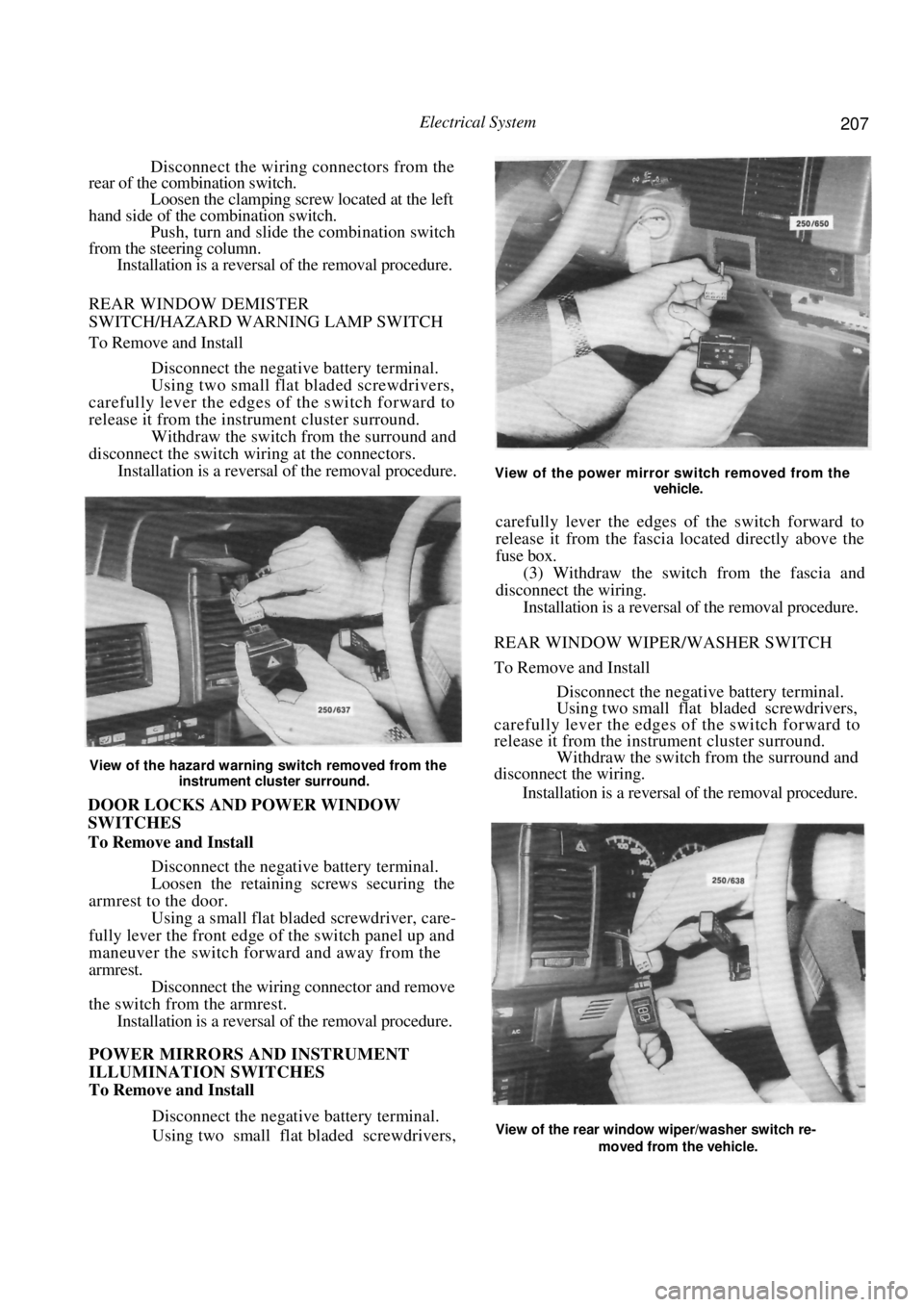
View of the combination switch removed from the
vehicle.
Release the column adjusting lever and re-
move the lower cover by guiding the column adjusting
lever through the hole in the upper end of the cover. Disconnect the wiring connectors from the
applicable switch. Remove the retaining screws located at the
top and bottom of the applicable switch and remove
the switch. Installation is a reversal of the removal procedure.
To Remove and Install Combination Switch Base
Disconnect the negative battery terminal.
Remove the steering wheel as described in
the Steering section Remove the retaining screws from the steer-
ing column cover. Unclip and separate the upper and lower
steering column covers and remove the upper cover.
Release the column adjusting lever and re-
move the lower cover by guiding the column adjusting
lever through the hole in the upper end of the cover.
Dismantled view of the steering lock and ignition
switch assembly
Page 207 of 238

Electrical System 207
Disconnect the wiring connectors from the
rear of the combination switch.
Loosen the clamping screw located at the left
hand side of the combination switch. Push, turn and slide the combination switch
from the steering column. Installation is a reversal of the removal procedure.
REAR WINDOW DEMISTER
SWITCH/HAZARD WARNING LAMP SWITCH
To Remove and Install
Disconnect the negative battery terminal.
Using two small flat bladed screwdrivers,
carefully lever the edges of the switch forward to
release it from the instrument cluster surround.
Withdraw the switch from the surround and
disconnect the switch wiri ng at the connectors.
Installation is a reversal of the removal procedure.
View of the hazard warning switch removed from the
instrument cluster surround.
DOOR LOCKS AND POWER WINDOW
SWITCHES
To Remove and Install
Disconnect the negative battery terminal.
Loosen the retaining screws securing the
armrest to the door. Using a small flat bladed screwdriver, care-
fully lever the front edge of the switch panel up and
maneuver the switch forward and away from the
armrest. Disconnect the wiring connector and remove
the switch from the armrest. Installation is a reversal of the removal procedure.
POWER MIRRORS AND INSTRUMENT
ILLUMINATION SWITCHES
To Remove and Install
Disconnect the negative battery terminal.
Using two small flat bladed screwdrivers,
View of the power mirror switch removed from the
vehicle.
carefully lever the edges of the switch forward to
release it from the fascia lo cated directly above the
fuse box.
(3) Withdraw the switch from the fascia and
disconnect the wiring.
Installation is a reversal of the removal procedure.
REAR WINDOW WIPER/WASHER SWITCH
To Remove and Install
Disconnect the negative battery terminal.
Using two small flat bladed screwdrivers,
carefully lever the edges of the switch forward to
release it from the instrument cluster surround. Withdraw the switch from the surround and
disconnect the wiring.
Installation is a reversal of the removal procedure.
View of the rear window wiper/washer switch re-
moved from the vehicle.
Page 235 of 238

Body 235
lever and remove the screws underneath. Withdraw
the rear console.
On manual transaxle models, unscrew the
gear lever knob and prise out the gear lever rubber
boot. On automatic transaxle models, prise out the
panel around the selector lever and maneuver the
panel over the lever. Remove the screws retaining the front of the
console to the floor panel and withdraw the console
from the vehicle. Installation is a reversal of the removal procedure.
9, DASHBOARD
TO REMOVE AND INSTAL
Disconnect the negative battery terminal.
Remove the centre console as previously
described in this section. Remove the steering wheel as described in
the Steering section. Remove the upper and lower steering col-
umn shrouds and remove the combination switch.
Refer to the Electrical System section if necessary. Remove the retaining screws and withdraw
the lower trim panel from underneath the steering
column. Remove the screws from underneath the
bonnet lock handle and slide the bonnet lock handle
downwards out of the dashboard. Remove the screws retaining the centre fas-
cia panel, two upper and two lower, withdraw the
fascia panel slightly and disconnect the wiring to the
cigarette lighter.
Dismantled view of the centre console assembly. Au-
tomatic transaxle model.
Remove the radio/cassette bracket retaining
screws. Disconnect the aerial and the wiring and
withdraw the radio/cassette from the centre bracket. Remove the heater control knobs and re-
move the heater fascia panel screws. Carefully remove
the heater fascia panel leaving the heater controls in
place.
Loosen the bolt retaining the large wiring
connector at the lower right hand side of the dash-
board. As the bolt is loosened it will force the
connector apart. Using a screwdriver, carefully prise out the
demister ducts from th e top of the dashboard.
Using a suitable socket, remove the bolts
from underneath the demister ducts. Remove the bolts from the outer lower edges
and the lower part of th e centre bracket assembly.
NOTE: Refer to the illustration for the
location of the dashboard retaining bolts.
(14) With the aid of an assistant lift the dash-
board straight up at the door pillar brackets. Tilt the
View of the dashboard removed from the vehicle. The arrows indicate the location of the retaining bolts.