steering NISSAN PULSAR 1987 User Guide
[x] Cancel search | Manufacturer: NISSAN, Model Year: 1987, Model line: PULSAR, Model: NISSAN PULSAR 1987Pages: 238, PDF Size: 28.91 MB
Page 35 of 238
Roadside Trouble Shooting 35
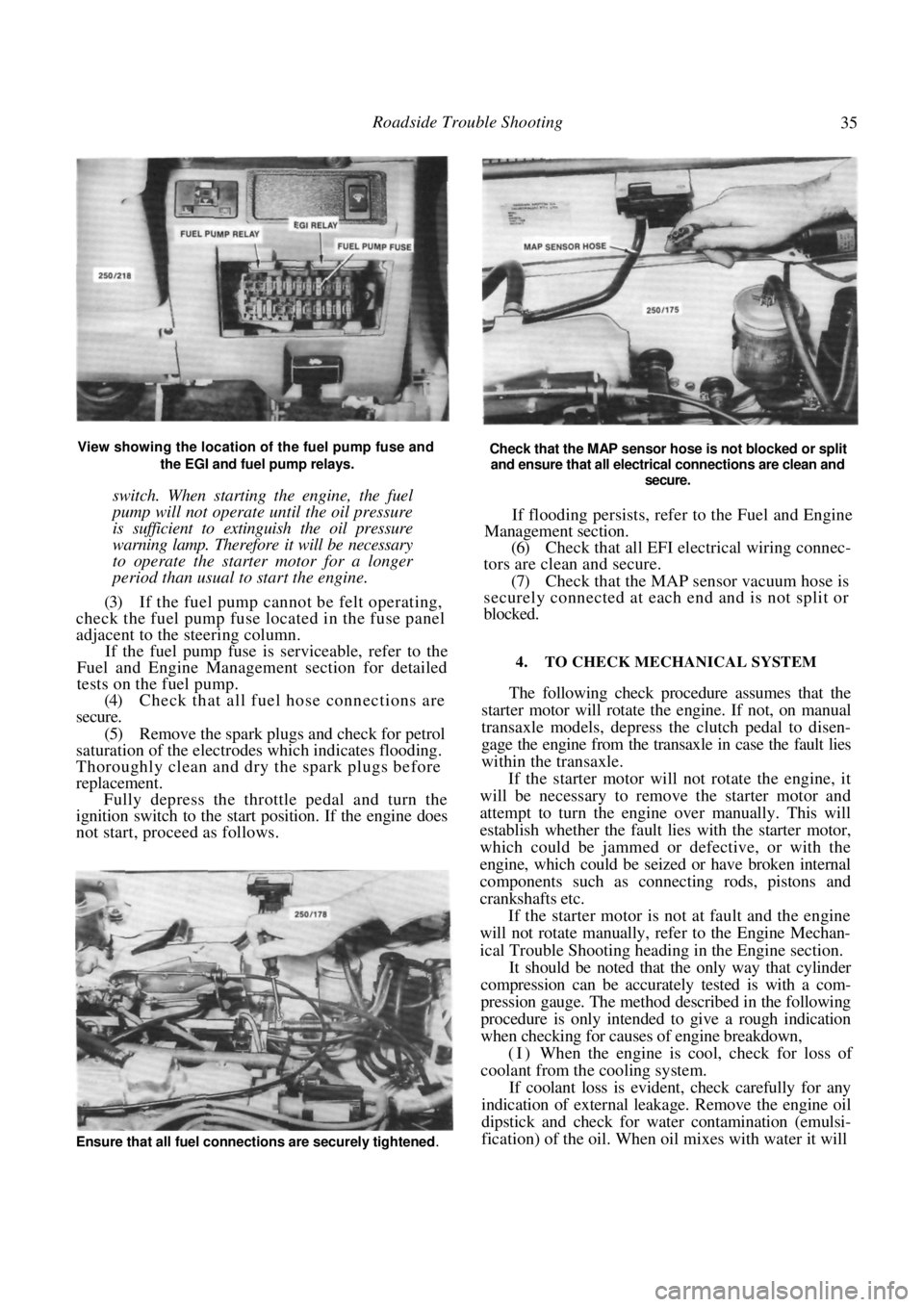
View showing the location of the fuel pump fuse and the EGI and fuel pump relays.
switch. When starting the engine, the fuel
pump will not operate until the oil pressure
is sufficient to extinguish the oil pressure
warning lamp. Therefore it will be necessary
to operate the starter motor for a longer
period than usual to start the engine.
(3) If the fuel pump cannot be felt operating,
check the fuel pump fuse located in the fuse panel
adjacent to the steering column.
If the fuel pump fuse is serviceable, refer to the
Fuel and Engine Management section for detailed
tests on the fuel pump.
(4) Check that all fuel hose connections are
secure.
(5) Remove the spark plugs and check for petrol
saturation of the electrodes which indicates flooding.
Thoroughly clean and dry the spark plugs before
replacement. Fully depress the throttle pedal and turn the
ignition switch to the start position. If the engine does
not start, proceed as follows.
Check that the MAP sensor hose is not blocked or split
and ensure that all electrical connections are clean and
secure.
If flooding persists, refer to the Fuel and Engine
Management section.
(6) Check that all EFI electrical wiring connec-
tors are clean and secure.
(7) Check that the MAP sensor vacuum hose is
securely connected at each end and is not split or
blocked.
4. TO CHECK MECHANICAL SYSTEM
The following check procedure assumes that the
starter motor will rotate the engine. If not, on manual
transaxle models, depress the clutch pedal to disen-
gage the engine from the tr ansaxle in case the fault lies
within the transaxle.
If the starter motor will not rotate the engine, it
will be necessary to remove the starter motor and
attempt to turn the engine over manually. This will
establish whether the fault lies with the starter motor,
which could be jammed or defective, or with the
engine, which could be seized or have broken internal
components such as connecting rods, pistons and
crankshafts etc.
If the starter motor is not at fault and the engine
will not rotate manually, refer to the Engine Mechan-
ical Trouble Shooting heading in the Engine section.
It should be noted that the only way that cylinder
compression can be accurately tested is with a com-
pression gauge. The method described in the following
procedure is only intended to give a rough indication
when checking for causes of engine breakdown,
(I) When the engine is cool, check for loss of
coolant from the cooling system.
If coolant loss is evident, check carefully for any
indication of external leakage. Remove the engine oil
dipstick and check for wate r contamination (emulsi-
fication) of the oil. When oil mixes with water it will
Ensure that all fuel connections are securely tightened.
Page 42 of 238

42 Engine
The cylinder block is a cast iron alloy, deep skirt
design and the crankshaft is supported in the cylinder
block by five precision insert replaceable main bear-
ings. Crankshaft end float is controlled by the flanged
centre main bearing. Connecting rods are I section
forgings equipped with precision insert replaceable big
end bearings. The gudgeon pins are an interference fit
in the connecting rod and a floating fit in the piston.
The cast aluminum pistons are equipped with
two compression rings and one oil control ring.
The twin rotor, involute gear oil pump is mounted
directly to the front face of the cylinder block. The
inner rotor is internally driven by the crankshaft. The
oil pump pressure relief valve is not adjustable, and
consists of a plunger and spring mounted in the oil
pump body.
The pump draws oil through a screen in the sump
and delivers it, via a full flow replaceable oil filter, to
the oil gallery from where it is distributed to the
hydraulic tappets, camshaft and crankshaft bearings
and to the overhead rocker and valve mechanism.
3. ENGINE AND TRANSAXLE ASSEMBLY
Special Equipment Required:
To Remove and Instill — Suitable lifting tackle,
extra long chassis stands, suitable trolley
TO REMOVE
NOTE: Due to the high residual pressure
within the fuel system, it will be necessary to
depressurize the system before removing any
fuel supply components. Refer to the Fuel
and Engine Management section for the
correct procedure.
(1) Disconnect the negative battery terminal.
(2) Mark around the bonnet hinges with a soft
lead pencil Co facilitate correct installation. With the
aid of an assistant, remove the bonnet retaining bolts
and remove the bonnet from the vehicle.
(3) Drain the engine and transaxle lubricant.
(4) Open the coolant drain tap located on the
lower radiator pipe and drain the coolant. (5) Loosen the hose clips and disconnect the
heater hoses from the heater pipes at the bulkhead.
NOTE: Do not use excessive force to remove
the heater hoses from the heater pipes or the
heater core will become dislodged from the
heater unit. If necessary, cut the heater
hoses from the pipes using a sharp knife.
(6) Loosen the hose clamps and disconnect the
radiator hoses from the engine assembly. (7) Disconnect the positive lead from the bat-
tery. (8) On 1.8 liter models, disconnect the air inlet
duct.
(9) On 1.6 liter models, remove the air cleaner
assembly. Refer to the Fuel and Engine Management
section if necessary. (10) Disconnect the throttle cable from the throt-
tle body and from the camshaft housing top cover
bracket, if applicable. (11) Disconnect the fuel supply and return hoses.
Mark the hoses as an aid to installation. (12) Suitably mark and disconnect the charcoal
canister hoses. (13) Disconnect the injector wires from the injec-
tors. On 1.6 liter models, slide the wiring out from the
throttle body. (14) Disconnect the wiring fr om the throttle po-
sition sensor (TPS), idle air control (IAC) valve,
oxygen (O
2) sensor wire, coolant temperature sensor,
coolant sender and on 1.8 liter models, the manifold
air temperature (MAT) sensor. (15) Disconnect the wiring connector adjacent to
the top heater hose, the wiring from the alternator and
the two earth wires from underneath the cylinder head
bolts. (16) Lay the wiring loom over on the passenger
side of the engine compar tment, clear of the work
area.
(17) On manual transaxle models, loosen the
clutch cable adjusting nuts and remove the cable
through the slot in the lever. Remove the clutch cable
bracket from the transaxle after removing the retain-
ing bolts and place the cable to one side.
(18) Disconnect the wiring from the starter mo-
tor, speedometer sender and on manual transaxle
models, the reverse lamp switch wiring.
(19) If applicable, disconnect the power steering
lines from the pump and drain the fluid into a
container. Suitably plug the lines and the pump to
prevent the entry of dirt.
(20) On automatic transaxle models, disconnect
the selector cable and bracket from the transaxle
assembly.
Disconnect the transaxle oil cooler lines from the
transaxle. Plug the lines and fittings to prevent the
entry of dirt etc.
(21) Loosen the front wheel nuts, raise the front
of the vehicle and support it on extra long chassis
stands. Ensure that the vehicle is high enough to allow
removal of the engine from underneath. (22) Remove the front wheels and the engine
splash guards from the vehicle.
(23) On manual transaxle models, remove the
stay rod and control rod bolts and nuts and disconnect
the rods from the transaxle.
(24) Remove the lower control arm to steering
knuckle ball joint nuts and separate the ball joints
from the steering knuckle by holding a dolly or a
hammer against one side of the steering knuckle and
hitting the other side with a hammer. The taper on the
ball joint will release fr om the steering knuckle.
(25) Pull the steering knuckles outward swiftly to
Page 44 of 238
44 Engine
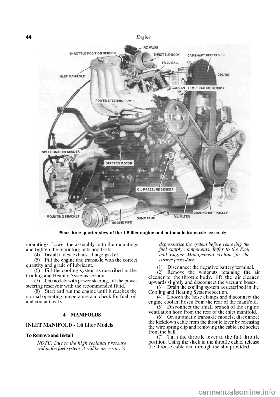
Rear three quarter view of the 1.8 liter engine and automatic transaxle assembly.
mountings. Lower the assembly onto the mountings
and tighten the mounting nuts and bolts.
(4) Install a new exhaust flange gasket.
(5) Fill the engine and transaxle with the correct
quantity and grade of lubricant. (6) Fill the cooling system as described in the
Cooling and Heating Systems section. (7) On models with power steering, fill the power
steering reservoir with the recommended fluid.
(8) Start and run the engine until it reaches the
normal operating temperatur e and check for fuel, oil
and coolant leaks.
4. MANIFOLDS
INLET MANIFOLD - 1.6 Liter Models
To Remove and Install
NOTE: Due to the high residual pressure
within the fuel system, it will be necessary to
depressurise the system before removing the
fuel supply components. Refer to the Fuel
and Engine Management section for the
correct procedure.
(1) Disconnect the negative battery terminal.
(2) Remove the wingnuts retaining the air
cleaner to the throttle body, lift the air cleaner
upwards slightly and disconnect the vacuum hoses. (3) Drain the cooling system as described in the
Cooling and Heating Systems section. (4) Loosen the hose clamps and disconnect the
engine coolant hoses from the rear of the manifold.
(5) Disconnect the small branch of the engine
ventilation hose from the rear of the inlet manifold. (6) On automatic transaxle models, disconnect
the kickdown cable from the throttle lever by releasing
the wire spring clip and re moving the cable end socket
from the ball.
(7) Turn the throttle lever to the full throttle
position. Using the slack in the throttle cable, release
the throttle cable end thr ough the slot provided.
Page 46 of 238
46 Engine
(1) Ensure that all carbon and old gasket mate-
rial is cleaned from the manifold and cylinder head
faces. (2) Check the face of the manifold for distortion
using a straight edge and a feeler gauge. (3) Use a new gasket and ensure that the mani-
fold retaining nuts are tightened to the specified
torque in a spiral pattern from the centre outwards. (4) Adjust the throttle cabl e as described in the
Fuel and Engine Management section and the kick-
down cable as described in the Automatic Transaxle
section.
(5) Start the engine and check for air, fuel and
water leaks.
EXHAUST MANIFOLD
To Remove and Install
(1) Bring the engine to operating temperature
and remove the oxygen sensor.
(2) Disconnect the negative battery terminal.
(3) On 1.6 liter models, remove the air cleaner
nuts, disconnect the vacuum hose and withdraw the
air cleaner from the vehicle. (4) Remove the front exhaust pipe flange mount-
ing nuts and separate the exhaust pipe from the
manifold. (5) Remove the heat shield retaining bolts and
withdraw the heat shield from the exhaust manifold. (6) Remove the exhaust manifold to cylinder
head retaining nuts and remove the manifold from the
engine. Discard the manifold gasket. Installation is a reversal of the removal procedure
with attention to the following points:
(1) Ensure that all carbon is cleaned from the
manifold and cylinder head mating surfaces. (2) Check the face of the manifold for distortion
using a straight edge and feeler gauges. (3) Use new gaskets on assembly.
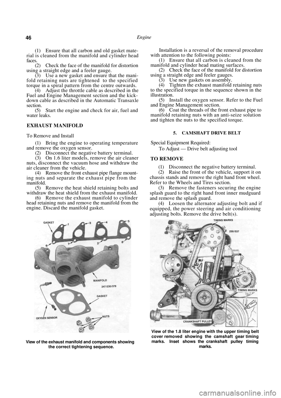
(4) Tighten the exhaust manifold retaining nuts
to the specified torque in the sequence shown in the
illustration. (5) Install the oxygen sensor. Refer to the Fuel
and Engine Management section. (6) Coat the threads of the front exhaust pipe to
manifold retaining nuts with an anti-seize solution
and tighten the nuts to the specified torque.
5. CAMSHAFT DRIVE BELT
Special Equipment Required:
To Adjust — Drive belt adjusting tool
TO REMOVE
(1) Disconnect the negative battery terminal.
(2) Raise the front of the vehicle, support it on
chassis stands and remove the right hand front wheel.
Refer to the Wheels and Tires section. (3) Remove the fasteners securing the engine
splash guard to the right hand front inner mudguard
and remove the splash guard. (4) Loosen the alternator adjusting bolt and if
equipped, the power steering and air conditioning
adjusting bolts. Remove the drive belt(s).
View of the exhaust manifold and components showing
the correct tightening sequence.
View of the 1.8 liter engine with the upper timing belt
cover removed showing the camshaft gear timing
marks. Inset shows the crankshaft pulley timing
marks.
Page 48 of 238
48 Engine
TO INSTAL
(1) Check that the camshaft and crankshaft
timing gears have not been moved and that the timing
marks are still aligned. It will be necessary to tempo-
rarily install the crankshaft pulley to check that the
timing marks are still aligned. (2) Install the drive belt to the crankshaft timing
gear around the water pump gear and onto the
camshaft timing gear.
NOTE: If the original drive belt is being
installed, ensure that the arrow marked on
the belt prior to removal is pointing in the
direction of rotation.
(3) Use the adjusting tool to turn the water
pump assembly sufficiently to engage the water pump
pulley with the drive belt. (4) Install the inner cover lower retaining bolt.
(5) Ensure that the drive be lt is correctly meshed
with the teeth of the camshaft, crankshaft and water
pump gears. Install the crankshaft pulley and tighten
the bolts to Specifications. (6) Adjust the drive belt as described under the
following heading.
(7) Install the drive belt outer cover and fasten
the retaining clips. (8) Install and adjust the alternator and if
equipped, the power steeri ng and air conditioning
drive belts as desc ribed in the Engine Tune-up section.
TO ADJUST
(1) Remove the alternator drive belt and if
equipped, the power steering and air conditioning
drive belts. (2) Release the clips securing the camshaft drive
belt outer cover to the inner cover and remove the
outer cover. (3) Turn the engine in the direction of rotation
until the timing marks on the camshaft and the inner
cover are aligned. (4) Loosen the water pump retaining bolts and
using the adjusting tool, rotate the water pump
housing to gain the required belt tension. The belt is
correctly tensioned when it can be grasped between
the thumb and forefinger midway between the cam-
shaft timing gear and the water pump gear and turned
ninety degrees from i t s operating position.
After the belt has been tensioned, tighten the
water pump retaining bolts to the specified torque.
NOTE: Over tensioning of the drive belt will
result in noisy operation and premature
wear of the belt.
(6) Install the outer drive belt cover.
(7) Install and adjust the alternator, and if
equipped, the power steering and air conditioning
drive belts as desc ribed in the Engine Tune-up section. 6. CAMSHAFT. ROCKER ARMS AND TAPPETS
Special Equipment Required:
To Check Camshaft — Dial gauge, Vee blocks and
micrometers
To Install — Drive belt adjusting tool
It is recommended that a new cylinder head
gasket is installed and the cylinder head bolts renewed
when the camshaft housing is removed.
TO REMOVE
(1) Disconnect the negative battery terminal.
Remove the nuts securing the earth wires to the
cylinder head bolts and remove the earth wires.
(2) On 1.6 liter models, remove the air cleaner
wingnuts and withdraw the air cleaner.
(3) Disconnect the engine breather hoses from
the camshaft housing and the camshaft housing top
cover. (4) Remove the camshaft housing top cover
retaining bolts and remove the top cover. Discard the
gasket.
(5) Remove the camshaft dr ive belt as described
under the previous heading. (6) Using an open ended spanner, hold the
camshaft between the inle t and exhaust lobes of
number four cylinder and remove the camshaft timing
gear retaining bolt and the camshaft timing gear.
(7) Remove the distributor, distributor cap and
high tension leads. If necessary refer to the Fuel and
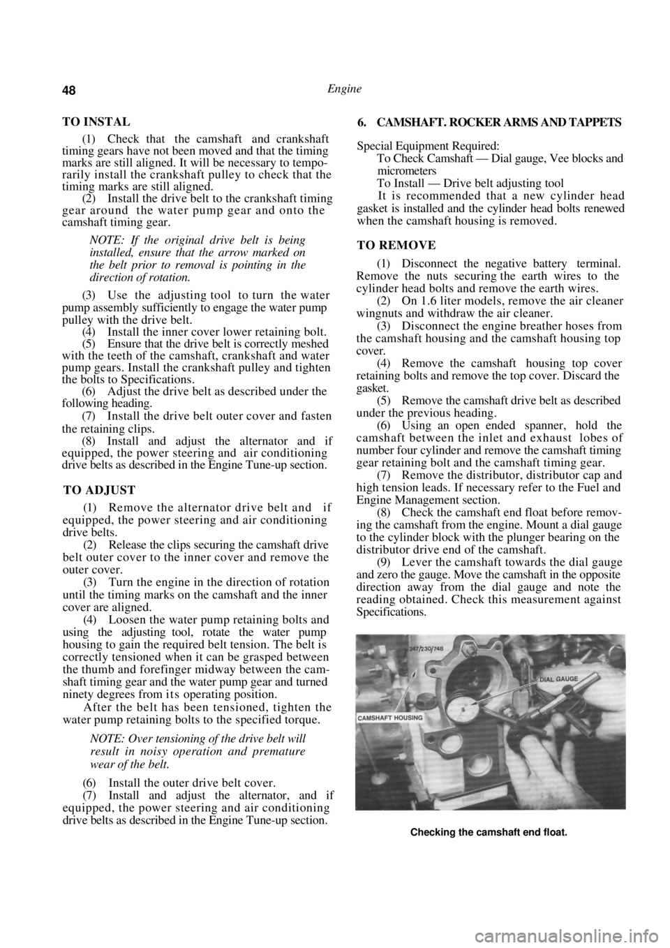
Engine Management section. (8) Check the camshaft end float before remov-
ing the camshaft from the engine. Mount a dial gauge
to the cylinder block with the plunger bearing on the
distributor drive end of the camshaft. (9) Lever the camshaft towards the dial gauge
and zero the gauge. Move the camshaft in the opposite
direction away from the dial gauge and note the
reading obtained. Check this measurement against
Specifications.
Checking the camshaft end float.
Page 78 of 238
78 Cooling and Heating Systems
The air conditioner operates only when the engine
is running as the compressor is belt driven from the
engine.
Operating the air conditioner with the tempera-
ture control raised to a hot setting will produce
dehumidified hot air which is particularly useful for
demisting the vehicle glass.
Maximum cooling is achieved by operating the air
conditioner with the temperature control lowered
fully to the coldest setting . Operate the fan at high
speed when using the coldest temperature setting to
avoid forming ice on the evaporator.
TO REMOVE AND INSTAL HEATER UNIT
(1) Remove the dashboard as described in the
Body section. (2) Drain the cooling system as previously de-
scribed in this section. (3) Loosen the hose clamps and disconnect the
heater hoses from the heater pipes.
NOTE: If the heater hos es will not come off
the heater pipes, do not use excess force or
the heater core retaining strap will be dam-
aged. Cut the hoses from the heater pipes.
(4) Remove the steering column upper mount-
ing bolts. (5) Remove the steering column cross support
bolts and move the support towards the right hand
side of the vehicle. (6) Remove the centre support retaining bolts
and remove the centre support from the vehicle.
(7) Remove the demister duct and the right
hand side ventilator duct from the vehicle. (8) Disconnect the blower fan wiring connector
from the rear of the heater controls. (9) Remove the heater retaining bolts.
(10) On models with air conditioning, it will be
necessary to loosen the evaporator mounting bolts. (11) Working in the engine compartment, push
the heater pipe grommet through the bulkhead. (12) Maneuver the heater unit upwards slightly
and out from the bulkhead using care not to damage
the heater pipes. (13) To remove the heater core and tap assembly,
remove the screws from the retaining strap and slide
the heater core from the heater unit.
Installation is a reversal of the removal procedure
with attention to the following points:
(1 ) Before installing the heater unit to the
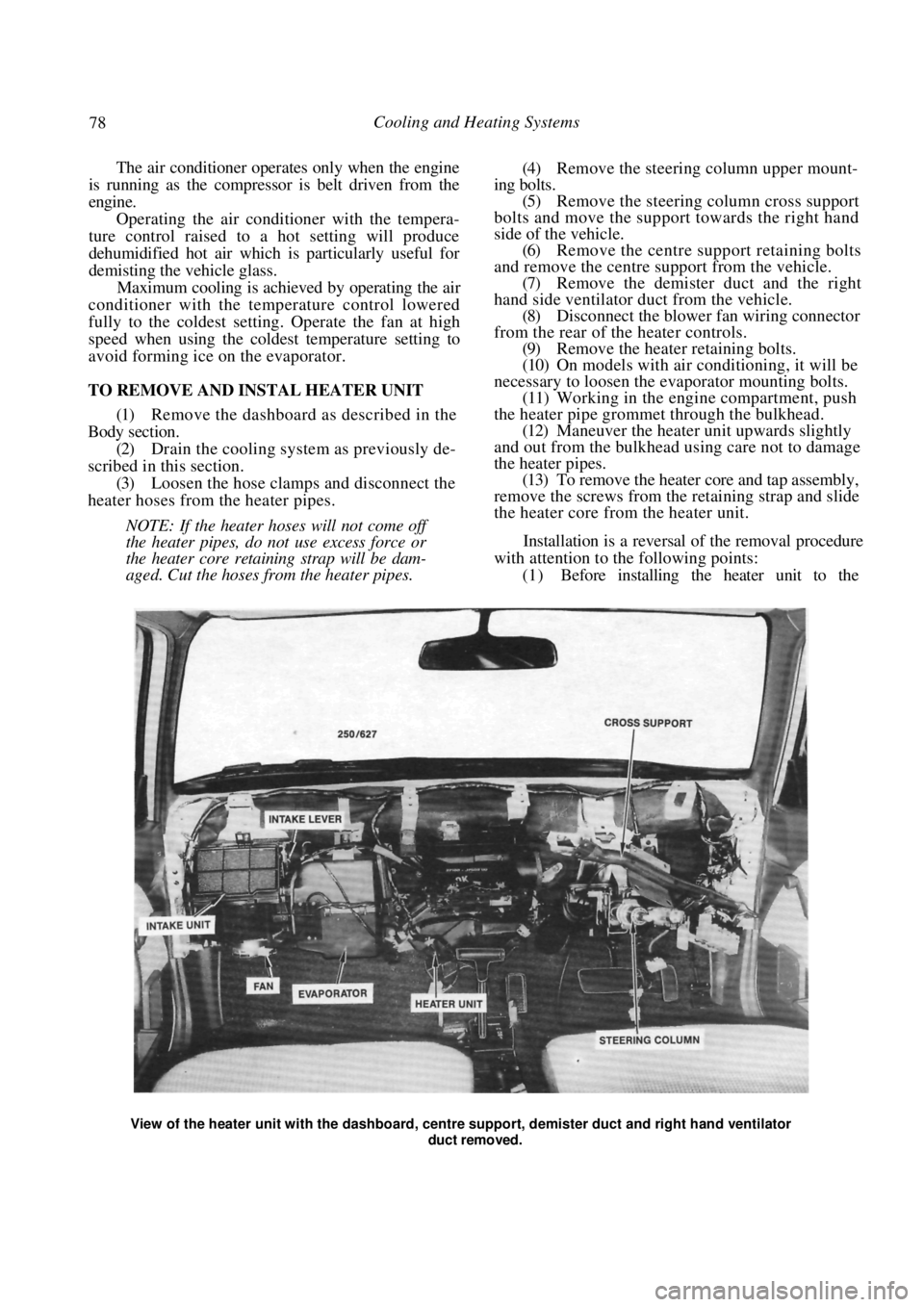
View of the heater unit with the dashboard, centr e support, demister duct and right hand ventilator
duct removed.
Page 90 of 238
90 Fuel and Engine Management
To identify the code number, count the number of
times the ECM warning lamp flashes. Each fault code
comprises two groups of flashes separated by a 1.2
second pause. The first group represents tens and the
second group represents single units. For example 1
flash followed by a 1.2 second pause followed by 4
flashes would be code number 14. Similarly 4 flashes
followed by a 1.2 second pause followed by 2 flashes
would be code number 42.
The code will be displayed three times. If more
than one fault code is present, the self diagnosis
system will indicate each one in numerical order, with
a 3.2 second pause between each code, and then
repeat the sequence.
The fault codes can be identified as follows:
CODE NUMBER FAULT AREA
12 Satisfactory operation
13 Oxygen sensor open circuit
14 Coolant temperature sensor circuit (voltage low)
15 Coolant temperature sensor circuit (voltage high)
21 Throttle position sensor circuit (voltage high)
22Throttle position sensor circuit (voltage low)
23MAT sensor circuit (voltage' high) 1.8 liter engine
only
24 Vehicle speed sensor circuit
25 MAT sensor circuit
(voltage low) 1.8 liter engine
only
33 MAP sensor circuit
(voltage high)
34MAP sensor circuit (voltage low)
42 Electronic spark timing circuit
44
Oxygen sensor circuit
(lean exhaust)
45Oxygen sensor circuit (rich exhaust)
51 Mem-Cal
55 Control unit input circuits
Test Procedure
(1) Perform the following checks:
(a) Ensure that the battery voltage is above 11
volts. (b) Ensure that the throttle valve is fully closed.
(c) Place the transaxle in neutral.
(d) Ensure that the air conditioner, fan, tights
and all other accessories are switched off.
(2) Turn the ignition On and confirm that the
ECM warning lamp on the instrument cluster is
illuminated but not flashing.
If code 55 is displayed, refer to the Control Unit
heading, perform the circuit test procedure and rectify
the cause of the code before proceeding.
If the ECM warning lamp flashes codes other than
code 55, check the wiring harness between the diag-
nostic link connector terminal B and the control unit
wiring connector terminal A9 for shorts. Repair or
renew the wiring harness as necessary.
If no fault can be found, renew the control unit.
If the ECM warning lamp does not illuminate,
proceed as follows:
(a) Check the METER fuse located in the fuse
panel adjacent to the steering column and the fusible
links located in the fusible link connecting block at the
rear of the battery. Renew the fuse or fusible links as
necessary. (b) Check the wiring harness to the instrument
cluster. Repair or renew the harness. (c) Check the Check Engine lamp bulb. Renew if
necessary. (d) Check the EGI relay. Renew as necessary.
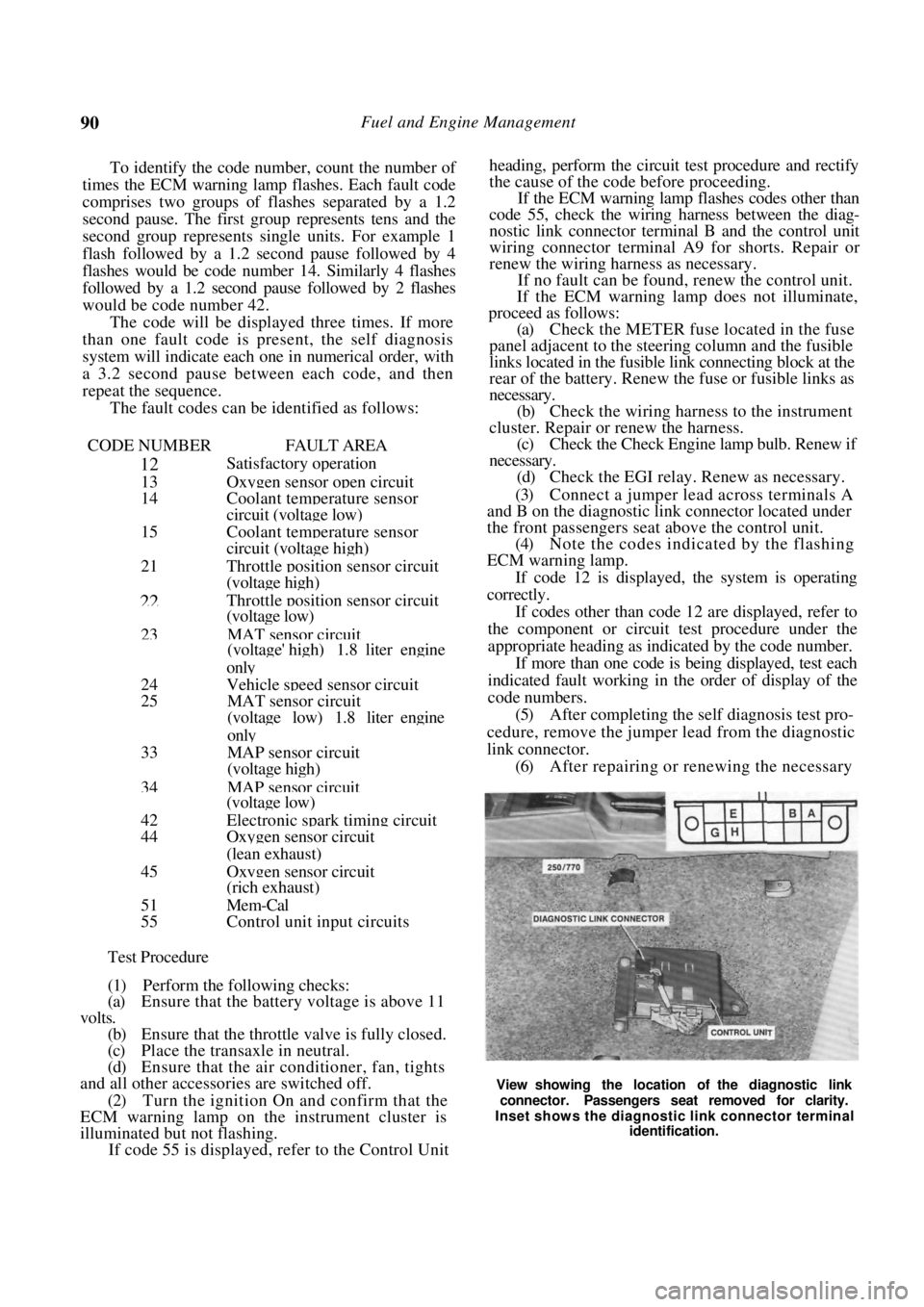
(3) Connect a jumper lead across terminals A
and B on the diagnostic link connector located under
the front passengers seat above the control unit.
(4) Note the codes indicated by the flashing
ECM warning lamp.
If code 12 is displayed, the system is operating
correctly.
If codes other than code 12 are displayed, refer to
the component or circuit test procedure under the
appropriate heading as indicated by the code number.
If more than one code is being displayed, test each
indicated fault working in the order of display of the
code numbers.
(5) After completing the self diagnosis test pro-
cedure, remove the jumper lead from the diagnostic
link connector. (6) After repairing or renewing the necessary
View showing the location of the diagnostic link
connector. Passengers seat removed for clarity.
Inset shows the diagnostic link connector terminal identification.
Page 108 of 238
108 Fuel and Engine Management
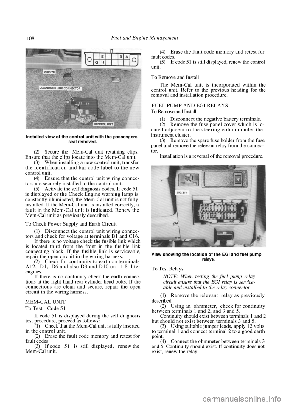
Installed view of the control unit with the passengers seat removed.
(2) Secure the Mem-Cal unit retaining clips.
Ensure that the clips locate into the Mem-Cal unit. (3) When installing a new control unit, transfer
the identification and bar code label to the new
control unit. (4) Ensure that the control unit wiring connec-
tors are securely installed to the control unit. (5) Activate the self diagnosis codes. If code 51
is displayed or the Check Engine warning lamp is
constantly illuminated, the Mem-Cal unit is not fully
installed. If the Mem-Cal uni t is installed correctly, a
fault in the Mem-Cal unit is indicated. Renew the
Mem-Cal unit as previously described.
To Check Power Supply and Earth Circuit
(1) Disconnect the control unit wiring connec-
tors and check for voltage at terminals B1 and C16.
If there is no voltage check the fusible link which
is located third from the front in the fusible link
connecting block. If the fu sible link is serviceable,
repair the open circuit in the wiring harness.
(2) Check for continuity to earth on terminals
A12, D1, D6 and also D3 and D10 on 1.8 liter
engines.
If there is no continuity check the earth connec-
tions at the right hand rear cylinder head bolts. If the
connections are clean and secure, repair the open
circuit in the wiring harness.
MEM-CAL UNIT
To Test - Code 51
If code 51 is displayed during the self diagnosis
test procedure, pr oceed as follows:
(1) Check that the Mem-Cal unit is fully inserted
in the control unit. (2) Erase the fault code memory and retest for
fault codes. (3) If code 51 is still displayed, renew the
Mem-Cal unit.
(4) Erase the fault code memory and retest for
fault codes. (5) If code 51 is still displayed, renew the control
unit.
To Remove and Install
The Mem-Cal unit is incorporated within the
control unit. Refer to the previous heading for the
removal and installation procedure.
FUEL PUMP AND EGI RELAYS
To Remove and Install
(1) Disconnect the negative battery terminals.
(2) Remove the fuse panel cover which is lo-
cated adjacent to the steering column under the
instrument cluster. (3) Remove the spare fuse holder from the fuse
panel and remove the releva nt relay from the connec-
tor. Installation is a reversal of the removal procedure.
View showing the location of the EGI and fuel pump
relays.
To Test Relays
NOTE: When testing the fuel pump relay
circuit ensure that th e EGI relay is service-
able and installed to the relay connector
(1) Remove the relevant relay as previously
described. (2) Using an ohmmeter, check for continuity
between terminals 1 and 2, and 3 and 5. Continuity should exist be tween terminals 1 and 2
but should not exist between terminals 3 and 5.
(3) Using suitable jumper leads, apply 12 volts
to terminal 1 and connect terminal 2 to a good earth
point. (4) Connect the ohmmeter between terminals 3
and 5. Continuity should exist. If continuity does not
exist, renew the relay.
Page 137 of 238
Manual Transaxle and Drive Shafts 137
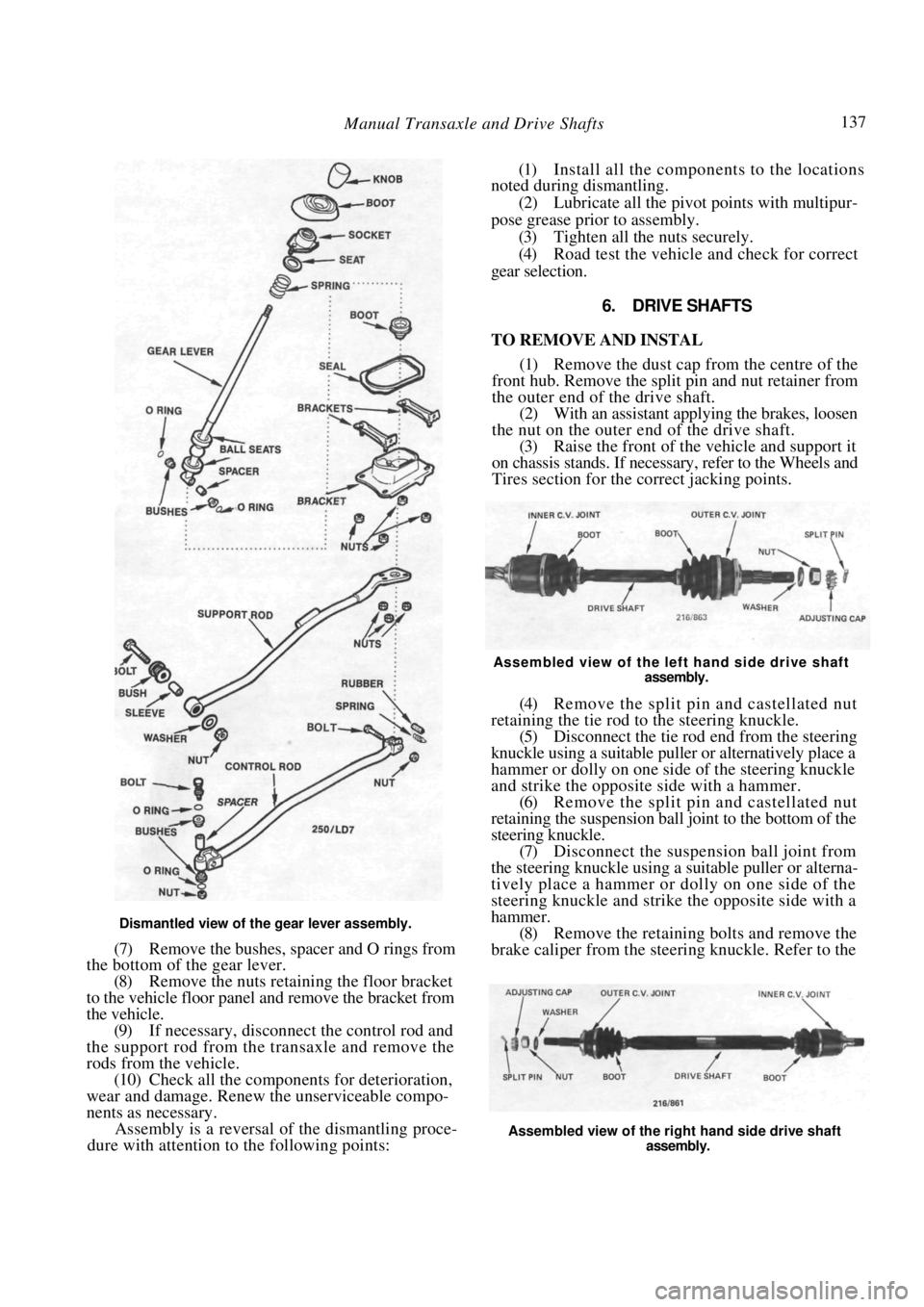
Dismantled view of the gear lever assembly.
(7) Remove the bushes, spacer and O rings from
the bottom of the gear lever.
(8) Remove the nuts retaining the floor bracket
to the vehicle floor panel and remove the bracket from
the vehicle. (9) If necessary, disconnect the control rod and
the support rod from the transaxle and remove the
rods from the vehicle. (10) Check all the components for deterioration,
wear and damage. Renew the unserviceable compo-
nents as necessary. Assembly is a reversal of the dismantling proce-
dure with attention to the following points:
(1) Install all the components to the locations
noted during dismantling.
(2) Lubricate all the pivot points with multipur-
pose grease prior to assembly. (3) Tighten all the nuts securely.
(4) Road test the vehicle and check for correct
gear selection.
6. DRIVE SHAFTS
TO REMOVE AND INSTAL
(1) Remove the dust cap from the centre of the
front hub. Remove the split pin and nut retainer from
the outer end of the drive shaft. (2) With an assistant applying the brakes, loosen
the nut on the outer end of the drive shaft.
(3) Raise the front of the vehicle and support it
on chassis stands. If necessary, refer to the Wheels and
Tires section for the correct jacking points.
Assembled view of the left hand side drive shaft
assembly.
(4) Remove the split pin and castellated nut
retaining the tie rod to the steering knuckle. (5) Disconnect the tie rod end from the steering
knuckle using a suitable puller or alternatively place a
hammer or dolly on one side of the steering knuckle
and strike the opposite side with a hammer.
(6) Remove the split pin and castellated nut
retaining the suspension ball joint to the bottom of the
steering knuckle. (7) Disconnect the suspension ball joint from
the steering knuckle using a suitable puller or alterna-
tively place a hammer or dolly on one side of the
steering knuckle and strike the opposite side with a
hammer. (8) Remove the retaining bolts and remove the
brake caliper from the stee ring knuckle. Refer to the
Assembled view of the right hand side drive shaft
assembly.
Page 138 of 238
138 Manual Transaxle and Drive Shafts
Brakes section if necessary. Suspend the caliper with
wire or cord attached to the coil spring.
(9) Hold the steering knuckle and hub assembly
and tap the drive shaft out of the hub using a soft
faced hammer.
(10) Drain the oil from the transaxle into a
container.
(11) Prise the drive shaft out of the transaxle and
remove the drive shaft from the vehicle.
Installation is a reversal of the removal procedure
with attention to the following points:
(1) Ensure that the drive sh aft is firmly attached
to the differential side gear by attempting to pull the
shaft out of the gear. (2) Tighten all nuts securely and install new split
pins. (3) Fill the transaxle with the specified grade and
quantity of oil.
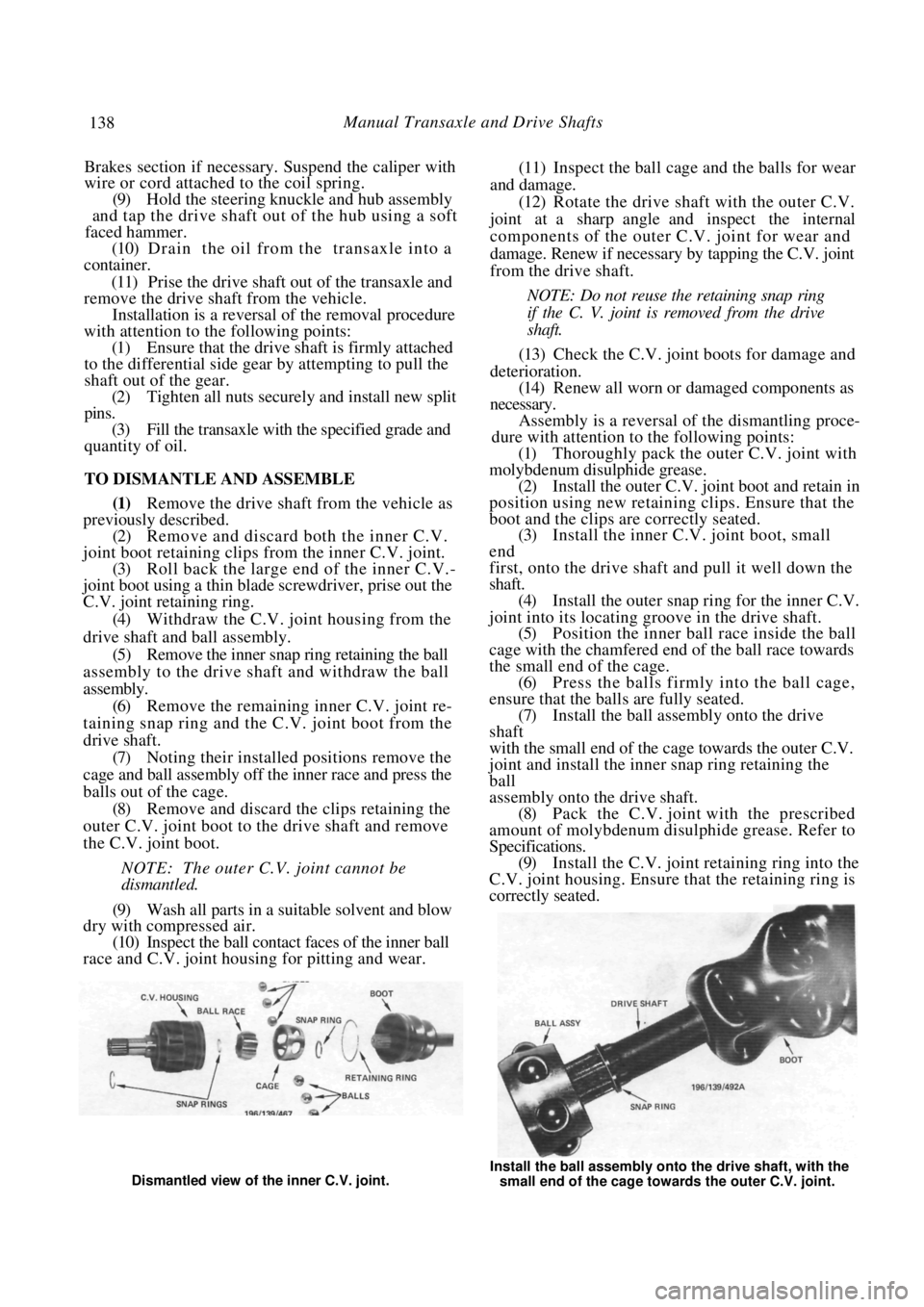
TO DISMANTLE AND ASSEMBLE
(1) Remove the drive shaft from the vehicle as
previously described.
(2) Remove and discard both the inner C.V.
joint boot retaining clips from the inner C.V. joint. (3) Roll back the large en d of the inner C.V.-
joint boot using a thin blade screwdriver, prise out the
C.V. joint retaining ring.
(4) Withdraw the C.V. joint housing from the
drive shaft and ball assembly. (5) Remove the inner snap ring retaining the ball
assembly to the drive shaft and withdraw the ball
assembly. (6) Remove the remaining inner C.V. joint re-
taining snap ring and the C.V. joint boot from the
drive shaft. (7) Noting their installed positions remove the
cage and ball assembly off the inner race and press the
balls out of the cage. (8) Remove and discard the clips retaining the
outer C.V. joint boot to the drive shaft and remove
the C.V. joint boot.
NOTE: The outer C.V. joint cannot be
dismantled.
(9) Wash all parts in a suitable solvent and blow
dry with compressed air.
(10) Inspect the ball contact faces of the inner ball
race and C.V. joint housing for pitting and wear.
(11) Inspect the ball cage and the balls for wear
and damage. (12) Rotate the drive shaft with the outer C.V.
joint at a sharp angle and inspect the internal
components of the outer C.V. joint for wear and
damage. Renew if necessary by tapping the C.V. joint
from the drive shaft.
NOTE: Do not reuse the retaining snap ring
if the C. V. joint is removed from the drive
shaft.
(13) Check the C.V. joint boots for damage and
deterioration. (14) Renew all worn or damaged components as
necessary. Assembly is a reversal of the dismantling proce-
dure with attention to the following points:
(1) Thoroughly pack the outer C.V. joint with
molybdenum disulphide grease. (2) Install the outer C.V. joint boot and retain in
position using new retaining clips. Ensure that the
boot and the clips ar e correctly seated.
(3) Install the inner C.V. joint boot, small
end
first, onto the drive shaft and pull it well down the
shaft. (4) Install the outer snap ri ng for the inner C.V.
joint into its locating groove in the drive shaft. (5) Position the inner ball race inside the ball
cage with the chamfered end of the ball race towards
the small end of the cage. (6) Press the balls firmly into the ball cage,
ensure that the balls are fully seated. (7) Install the ball assem bly onto the drive
shaft
with the small end of the cage towards the outer C.V.
joint and install the inner snap ring retaining the
ball
assembly onto the drive shaft.
(8) Pack the C.V. joint with the prescribed
amount of molybdenum disul phide grease. Refer to
Specifications. (9) Install the C.V. joint retaining ring into the
C.V. joint housing. Ensure that the retaining ring is
correctly seated.
Dismantled view of the inner C.V. joint. Install the ball assembly onto the drive shaft, with the
small end of the cage towards the outer C.V. joint.