ECO mode NISSAN PULSAR 1987 Workshop Manual
[x] Cancel search | Manufacturer: NISSAN, Model Year: 1987, Model line: PULSAR, Model: NISSAN PULSAR 1987Pages: 238, PDF Size: 28.91 MB
Page 5 of 238

INTRODUCTION
This Service and Repair Manual
covers the Australian manufac-
tured Nissan Pulsar (hatchback) and Vector (sedan) N13 Series 1
(J87 - 91 and
the Holden Astra LD Series 1987 - 89.
Two engines were available: a 1.8 l i t e r engine with multi-point fuel injec-
tion, and a 1.6 liter throttle body injected engine. The engines are similar
having single overhead camshafts and computer controlled fuel injection and
ignition control. There was a choice of three speed automatic or five speed
manual transaxles.
A viscous coupling limited s l i p differential was introduced from July 1989
to the five speed manual transaxle models of the Pulsar Q and Vector SSS.
Disc brakes are fitted at the front of a l l models, while the rear brakes are
either discs or drums.
All models are equipped with independent coil spring suspension. Steering
can be by either manual or power assisted rack and pinion.
This manual includes information on trouble shooting, lubrication and
maintenance, specifications and the rem oval, installation and overhaul of com-
ponents which are considered to be with in the scope of the average, well
equipped home mechanic.
Certain repair jobs covered in this manual require the use of special
equipment not normally found in a home tool kit. When such equipment is
required, the equipment and i t s functi on is brought to the users attention
underneath the heading for that component. Some jobs, such as automatic
transmission overhaul, should he left to an authorized dealer or a specialist
who has the extensive knowledge and equi pment required. In these cases, the
removal and installation procedures are fully covered, enabling the unit to be
removed for repair or a reconditioned unit to be installed.
Reference in the manual to the left an d right hand sides of the vehicle are
from the point of view of someone sta nding at the back of the vehicle and
looking forward.
Inexperienced operators should not a ttempt a service or repair operation
before completely reading the appropriat e section (or other sections which may
be referred to) in the manual.
Page 21 of 238
WHEELS AND TYRES
SPECIFICATIONS
TYRES PRESSURES
Front:
Normal load ............................................ 200 kPa
Heavy load or high speed ......................230 kPa
Rear:
Normal load............................................ 180 kPa
Heavy load or high speed ...................... 210 kPa
NOTE: The above pressures are measured
cold and are meant as a guide only. Always
refer to the tire placard positioned on the
inside of the glove compartment lid and the
tire manufacturers recommendations first.
TORQUE WRENCH SETTINGS
Wheel nut torque .............................................98 Nm
1. HOW TO CHANGE A ROAD WHEEL
(1) Ensure that the vehicle is on level firm
ground and clear of any passing traffic. (2) If necessary, switch on the hazard
flashers.
(3) Switch off the engine a nd place the transaxle
in the (P) Park position on automatic transaxle
models or in reverse gear on manual transaxle models.
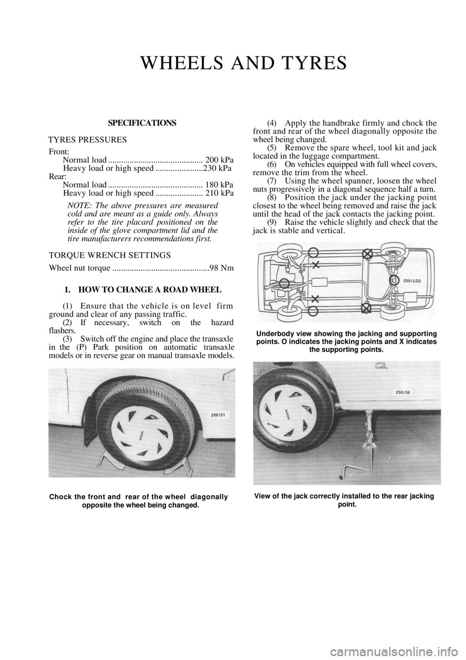
(4) Apply the handbrake firmly and chock the
front and rear of the wheel diagonally opposite the
wheel being changed.
(5) Remove the spare wheel, tool kit and jack
located in the luggage compartment. (6) On vehicles equipped with full wheel covers,
remove the trim from the wheel. (7) Using the wheel spanner, loosen the wheel
nuts progressively in a diagonal sequence half a turn.
(8) Position the jack und er the jacking point
closest to the wheel being removed and raise the jack
until the head of the jack contacts the jacking point.
(9) Raise the vehicle slightly and check that the
jack is stable and vertical.
Underbody view showing the jacking and supporting
points. O indicates the jacking points and X indicates
the supporting points.
Chock the front and rear of the wheel diagonally
opposite the wheel being changed. View of the jack correctly installed to the rear jacking
point.
Page 26 of 238
26 Engine Tune-up
1.6 Liter Engine
(1) Remove the nuts and washers securing the
upper air cleaner housing to the lower air cleaner
housing and release the retaining clips. (2) Remove the air cleaner element.
(3) Clean the inside of the air cleaner housing
using a damp rag to remo ve all traces of dust.
(4) Install a new air cleaner element ensuring that
the element is correctly seated around the edges.
(5) Install the upper housing and secure the
retaining clips. Tighten th e retaining nuts securely.
TO RENEW FUEL FILTER
filter should
The fuel
40 000 km.
(1) Depressurize the fuel system using the fol-
lowing procedure:
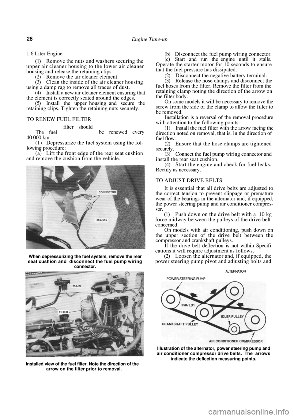
(a) Lift the front edge of the rear seat cushion
and remove the cushion from the vehicle.
When depressurizing the fuel system, remove the rear
seat cushion and disconnect the fuel pump wiring
connector.
(b) Disconnect the fuel pump wiring connector.
(c) Start and run the engine until it stalls.
Operate the starter motor for 10 seconds to ensure
that the fuel pressure has dissipated.
(2) Disconnect the negative battery terminal.
(3) Release the hose clamps and disconnect the
fuel hoses from the filter. Remove the filter from the
retaining clamp noting the direction of the arrow on
the filter body. On some models it will be necessary to remove the
screw from the side of the clamp to allow the filler to
be removed.
Installation is a reversal of the removal procedure
with attention to the following points:
(1) Install the fuel filter with the arrow facing the
direction noted on removal, that is, in the direction of
fuel flow.
(2) Ensure that the hose clamps are tightened
securely.
(3) Connect the fuel pump wiring connector and
install the rear seat cushion. (4) Start the engine and check for fuel leaks.
Rectify as necessary.
TO ADJUST DRIVE BELTS
It is essential that all drive belts are adjusted to
the correct tension to prevent slippage or premature
wear of the bearings in the alternator and, if equipped,
the power steering pump and air conditioner compres-
sor.
(1) Push down on the drive belt with a 10 kg
force midway between the pulleys of the drive belt
concerned.
On models with air conditioning, push down on
the upper section of the drive belt between the
compressor and crankshaft pulleys.
If the drive belt deflection is not within Specifi-
cations it will require adjustment as follows.
(2) Loosen the alternator and, if equipped, the
power steering pump pivot and adjusting bolts and
ALTERNATOR
POWER STEERING PUMP
be renewed every
Installed view of the fuel filter. Note the direction of the arrow on the filter prior to removal. Illustration of the alternator, power steering pump and
air conditioner compressor drive belts. The arrows
indicate the deflection measuring points.
Page 27 of 238
Engine Tune-up 27
move the alternator or power steering pump as
required until the drive belt concerned has the
specified deflection.
On models with air conditioning, loosen the nut
in the centre of the idler pulley and turn the adjusting
bolt until the drive belt has the specified deflection.
(3) Tighten the alternator or power steering
pump bolts securely and check the belt tension.
On models with air conditioning, tighten the idler
pulley nut securely.
TO SERVICE SPARK PLUGS
The spark plugs should be renewed at intervals of
40 000 km.
Before removing the spark plugs ensure that the
area around each plug is cl ean to prevent foreign
matter entering the cylinder when the plugs are
removed.
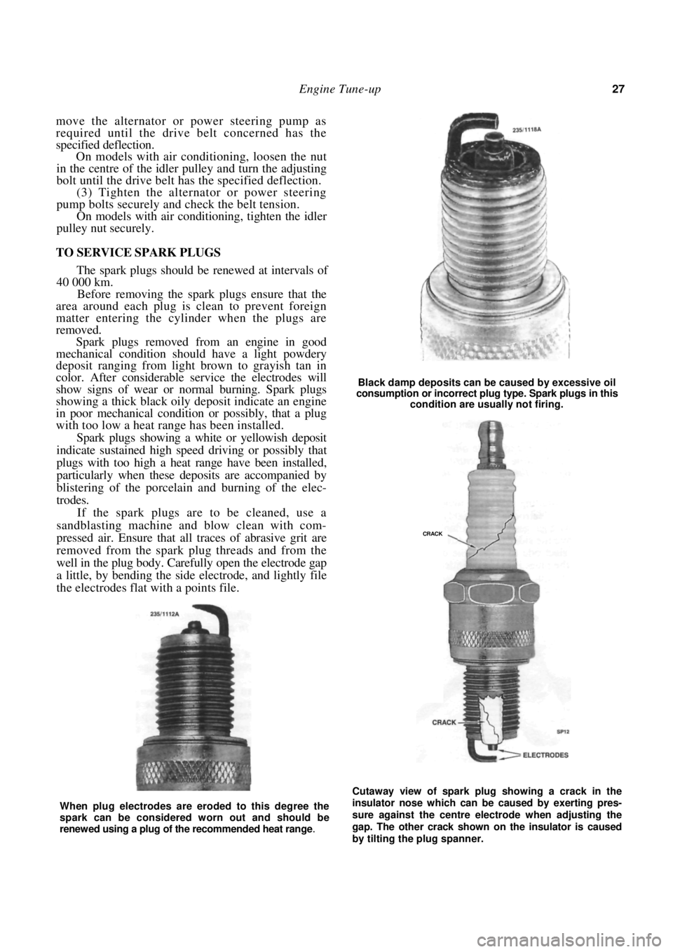
Spark plugs removed from an engine in good
mechanical condition should have a light powdery
deposit ranging from light brown to grayish tan in
color. After considerable service the electrodes will
show signs of wear or no rmal burning. Spark plugs
showing a thick black oily deposit indicate an engine
in poor mechanical condition or possibly, that a plug
with too low a heat range has been installed.
Spark plugs showing a white or yellowish deposit
indicate sustained high speed driving or possibly that
plugs with too high a heat range have been installed,
particularly when these deposits are accompanied by
blistering of the porcelain and burning of the elec-
trodes.
If the spark plugs are to be cleaned, use a
sandblasting machine and blow clean with com-
pressed air. Ensure that all traces of abrasive grit are
removed from the spark plug threads and from the
well in the plug body. Carefully open the electrode gap
a little, by bending the side electrode, and lightly file
the electrodes flat with a points file.
Black damp deposits can be caused by excessive oil
consumption or incorrect plug type. Spark plugs in this
condition are usually not firing.
Cutaway view of spark plug showing a crack in the
insulator nose which can be caused by exerting pres-
sure against the centre electrode when adjusting the
gap. The other crack shown on the insulator is caused
by tilting the plug spanner.
When plug electrodes are eroded to this degree the
spark can be considered worn out and should be
renewed using a plug of the recommended heat range
.
CRACK
Page 33 of 238
Roadside Trouble Shooting
(5) Place the vent caps loosely over the cell
apertures.
(6) Connect one end of the red jumper lead to
the positive ( + ) battery terminal of the booster
battery and the other end of the red lead to the
positive (+) battery terminal of the discharged bat-
tery.
NOTE: The battery emits hydrogen gas
which is explosive. Do not expose the battery
to naked /lames or sparks.
Do not lean over the battery when con-
necting the jumper leads.
Do not allow the ends of the jumper leads
to touch one another or any part of the
engine.
(7) Connect one end of the black juniper lead to
the negative (-) battery terminal of the booster
battery and the other end of the black lead to a good
earthing point on the engine of the vehicle with the
discharged battery.
NOTE: Do not connect the jumper lead
directly to the negative (-) battery terminal
of the discharged battery.
(8) Start the engine on the vehicle with the
booster battery and run the engine at a moderate
speed. (9) Start the engine on the vehicle with the
discharged battery.
(10) If possible, leave the engines of both vehi-
cles running for 10 minutes.
(11) Disconnect the jumper leads in the reverse
order of the sequence in which they were connected.
2. TO CHECK IGNITION AND ELECTRICAL SYSTEM
(1) Switch on the ignition and check for warning
lamp illumination on the dashboard. (2) Operate the starter and check that the starter
rotates the engine at a steady speed.
(3) Switch on the headlamps and check for good
light intensity. Should the lamps not illum inate or the starter
motor not turn the engine, carry out the following
steps:
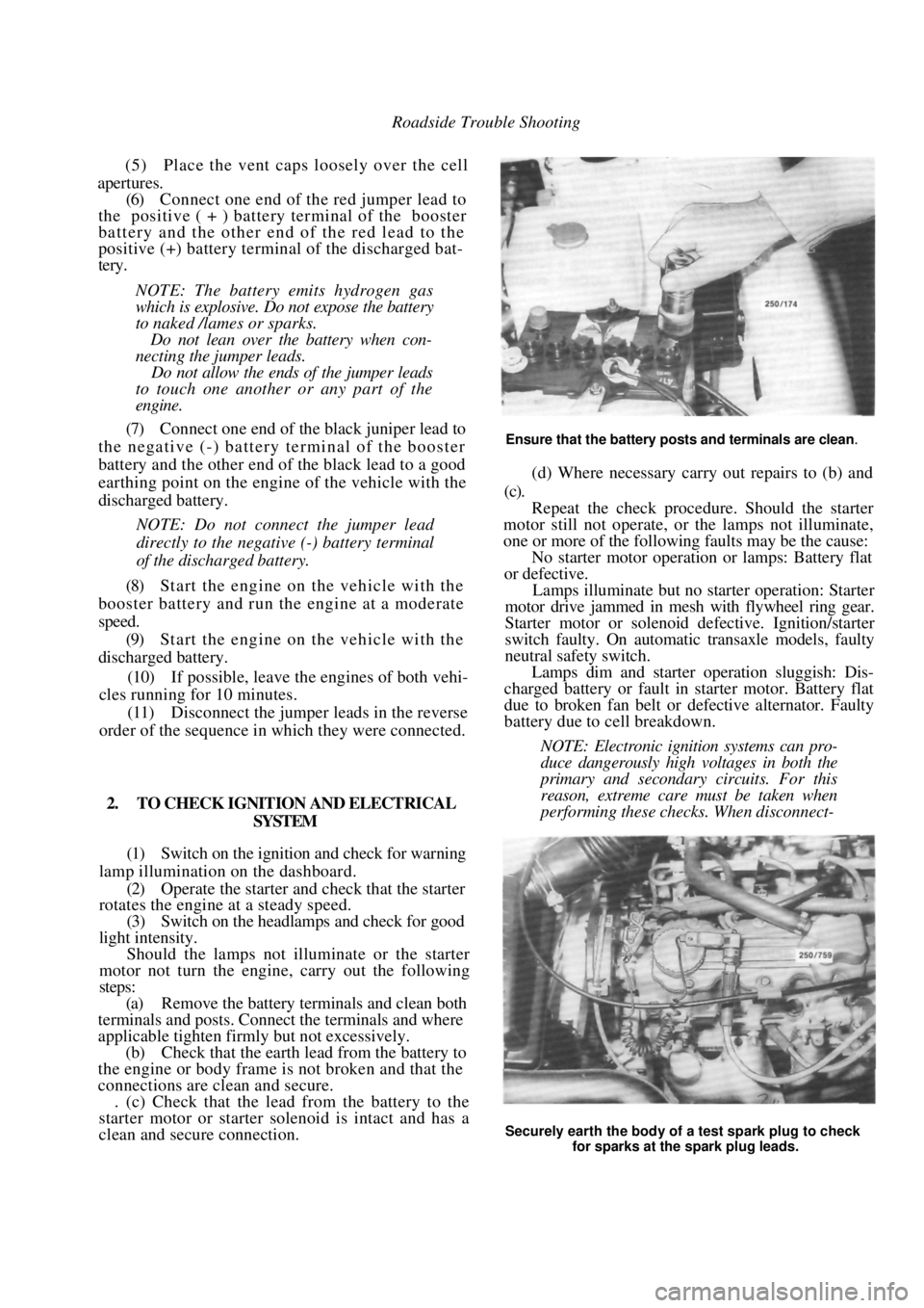
(a) Remove the battery terminals and clean both
terminals and posts. Connect the terminals and where
applicable tighten firmly but not excessively.
(b) Check that the earth lead from the battery to
the engine or body frame is not broken and that the
connections are clean and secure. . (c) Check that the lead from the battery to the
starter motor or starter solenoid is intact and has a
clean and secure connection.
Ensure that the battery posts and terminals are clean.
(d) Where necessary carry out repairs to (b) and
(c).
Repeat the check procedur e. Should the starter
motor still not operate, or the lamps not illuminate,
one or more of the following faults may be the cause:
No starter motor operation or lamps: Battery flat
or defective.
Lamps illuminate but no starter operation: Starter
motor drive jammed in mesh with flywheel ring gear.
Starter motor or solenoid defective. Ignition/starter
switch faulty. On automatic transaxle models, faulty
neutral safety switch.
Lamps dim and starter operation sluggish: Dis-
charged battery or fault in starter motor. Battery flat
due to broken fan belt or de fective alternator. Faulty
battery due to cell breakdown.
NOTE: Electronic ignition systems can pro-
duce dangerously high voltages in both the
primary and secondary circuits. For this
reason, extreme care must be taken when
performing these checks. When disconnect-
Securely earth the body of a test spark plug to check
for sparks at the spark plug leads.
Page 41 of 238

Engine 41
DROP IN OIL PRESSURE
(1) Oil level low in the sump: Check and replen-
ish the oil to the full mark on the dipstick.
(2) Thin or diluted oil: Change to the correct oil
grade and rectify the source of dilution. (3) Oil pump relief valve stuck or spring broken;
Free up the relief valve or renew the broken relief
valve spring. (4) Excessive bearing clearance: Renew the bear-
ing shells or recondition the crankshaft journals as
necessary.
(5) Excessive wear of the oil pump components:
Renew or recondition the oil pump.
NOTE: If the vehicle is not equipped with an
oil pressure gauge re move the oil sender unit
and connect a pressure gauge into the oil
gallery. Check the oil pressure with the
engine cold and hot. If the oil pump or relief
valve are faulty. low pressure will be indi-
cated with the engine both hot and cold.
However, if the bearings are at fault a fairly
high oil pressure will be indicated when the
engine is cold, but a marked drop in pressure
will occur when the engine is hot.
ENGINE WILL NOT ROTATE
(1) Starter motor drive jammed: Remove the
starter motor. Check and renew the damaged drive
and/or flywheel ring gear.
(2) Engine overheated an d seized: Remove and
dismantle the engine. Check and renew any damaged
components. See the following note.
(3) Water in the cylinder due to a blown head
gasket or cracked cylinder block or head: Remove the
cylinder head. If the gasket is blown, check for
cylinder block and head distortion and reface if
necessary. Renew the cylinder head and/or cylinder
block if cracked.
(4) Broken crankshaft, connecting rod. piston
etc. due to overheating, fatigue etc: Remove and
dismantle the engine. Examine and renew any com-
ponents as necessary. (5) Valve head broken off due to overheating,
fatigue etc: Remove the cylinder head and check the
head, piston and cylinder bore for damage. Repair or
renew as necessary.
NOTE: Invariably when an engine seizes
because of overheating due to lack of oil
and/or water, damage is done to the bear-
ings, pistons etc. Although there may be
instances where an engine will start and run
after it has cooled down and the oil and
water have been replenished, it will usually
be found that oil consumption increases, oil
pressure decreases and the engine will be
noisier, depending on the degree of damage.
When a cylinder head gasket blows allow-
ing water into the cylinders, or compression
loss between the cylinders, it is essential to
check the gasket faces on the cylinder block
and head for distortion. Sufficient water can
enter a cylinder because of a blown head
gasket, cracked cylinder or head to prevent
an engine from rotating.
This is normally preceded by difficult
starting, misfiring, excessive steam from the
exhaust and loss of water from the radiator.
Frequent jamming of the starter motor
drive with the flywheel ring gear can be due
to a bent starter armature shaft or damaged
teeth on the drive and/or ring gear. With the
starter motor removed, the flywheel ring
gear teeth can be examined through the
starter motor mounting aperture. Renewal
of the ring gear requires removal of the
transaxle, clutch and flywheel on manual
transaxle models and the removal of the
transaxle and drive plate on automatic
transaxle models. To check for a bent arma-
ture shaft, rotate the shaft by hand while
holding the end in close proximity to a fixed
object.
2. DESCRIPTION
The 1.6 and 1.8 liter engines are basically identi-
cal in design.
Both engines share the same stroke. The 1.8 liter
engine has a larger bore thus giving it increased
capacity.
The engine is a four cylinder, inline, overhead
camshaft design transversely mounted in the front of
the vehicle.
The camshaft runs in five integral support bear-
ings in the camshaft housing which in turn is mounted
directly on to the cylinder head and retained by the
cylinder head bolts.
Camshaft end float is controlled by a retaining
plate engaged in a groove machined in the rear
camshaft journal. The camshaft is driven by the
crankshaft timing gear vi a a reinforced rubber belt.
The aluminum cross flow cylinder head houses
the tappets, rocker arms a nd valve assemblies. An oil
pressure relief valve is installed to the cylinder head to
maintain oil pressure to the hydraulic tappets at a
predetermined setting.
The exhaust valve springs are equipped with
rotators mounted below the valve springs which rotate
the exhaust valve assemblies. The rocker arms pivot
on hydraulic tappet assemblies and locate in notched
lash pads mounted on the valve stems. The camshaft
lobes bear directly onto the rocker arms and due to
the characteristics of the hydraulic tappet assemblies,
no provision is made for tappet clearance adjustment.
Page 42 of 238

42 Engine
The cylinder block is a cast iron alloy, deep skirt
design and the crankshaft is supported in the cylinder
block by five precision insert replaceable main bear-
ings. Crankshaft end float is controlled by the flanged
centre main bearing. Connecting rods are I section
forgings equipped with precision insert replaceable big
end bearings. The gudgeon pins are an interference fit
in the connecting rod and a floating fit in the piston.
The cast aluminum pistons are equipped with
two compression rings and one oil control ring.
The twin rotor, involute gear oil pump is mounted
directly to the front face of the cylinder block. The
inner rotor is internally driven by the crankshaft. The
oil pump pressure relief valve is not adjustable, and
consists of a plunger and spring mounted in the oil
pump body.
The pump draws oil through a screen in the sump
and delivers it, via a full flow replaceable oil filter, to
the oil gallery from where it is distributed to the
hydraulic tappets, camshaft and crankshaft bearings
and to the overhead rocker and valve mechanism.
3. ENGINE AND TRANSAXLE ASSEMBLY
Special Equipment Required:
To Remove and Instill — Suitable lifting tackle,
extra long chassis stands, suitable trolley
TO REMOVE
NOTE: Due to the high residual pressure
within the fuel system, it will be necessary to
depressurize the system before removing any
fuel supply components. Refer to the Fuel
and Engine Management section for the
correct procedure.
(1) Disconnect the negative battery terminal.
(2) Mark around the bonnet hinges with a soft
lead pencil Co facilitate correct installation. With the
aid of an assistant, remove the bonnet retaining bolts
and remove the bonnet from the vehicle.
(3) Drain the engine and transaxle lubricant.
(4) Open the coolant drain tap located on the
lower radiator pipe and drain the coolant. (5) Loosen the hose clips and disconnect the
heater hoses from the heater pipes at the bulkhead.
NOTE: Do not use excessive force to remove
the heater hoses from the heater pipes or the
heater core will become dislodged from the
heater unit. If necessary, cut the heater
hoses from the pipes using a sharp knife.
(6) Loosen the hose clamps and disconnect the
radiator hoses from the engine assembly. (7) Disconnect the positive lead from the bat-
tery. (8) On 1.8 liter models, disconnect the air inlet
duct.
(9) On 1.6 liter models, remove the air cleaner
assembly. Refer to the Fuel and Engine Management
section if necessary. (10) Disconnect the throttle cable from the throt-
tle body and from the camshaft housing top cover
bracket, if applicable. (11) Disconnect the fuel supply and return hoses.
Mark the hoses as an aid to installation. (12) Suitably mark and disconnect the charcoal
canister hoses. (13) Disconnect the injector wires from the injec-
tors. On 1.6 liter models, slide the wiring out from the
throttle body. (14) Disconnect the wiring fr om the throttle po-
sition sensor (TPS), idle air control (IAC) valve,
oxygen (O
2) sensor wire, coolant temperature sensor,
coolant sender and on 1.8 liter models, the manifold
air temperature (MAT) sensor. (15) Disconnect the wiring connector adjacent to
the top heater hose, the wiring from the alternator and
the two earth wires from underneath the cylinder head
bolts. (16) Lay the wiring loom over on the passenger
side of the engine compar tment, clear of the work
area.
(17) On manual transaxle models, loosen the
clutch cable adjusting nuts and remove the cable
through the slot in the lever. Remove the clutch cable
bracket from the transaxle after removing the retain-
ing bolts and place the cable to one side.
(18) Disconnect the wiring from the starter mo-
tor, speedometer sender and on manual transaxle
models, the reverse lamp switch wiring.
(19) If applicable, disconnect the power steering
lines from the pump and drain the fluid into a
container. Suitably plug the lines and the pump to
prevent the entry of dirt.
(20) On automatic transaxle models, disconnect
the selector cable and bracket from the transaxle
assembly.
Disconnect the transaxle oil cooler lines from the
transaxle. Plug the lines and fittings to prevent the
entry of dirt etc.
(21) Loosen the front wheel nuts, raise the front
of the vehicle and support it on extra long chassis
stands. Ensure that the vehicle is high enough to allow
removal of the engine from underneath. (22) Remove the front wheels and the engine
splash guards from the vehicle.
(23) On manual transaxle models, remove the
stay rod and control rod bolts and nuts and disconnect
the rods from the transaxle.
(24) Remove the lower control arm to steering
knuckle ball joint nuts and separate the ball joints
from the steering knuckle by holding a dolly or a
hammer against one side of the steering knuckle and
hitting the other side with a hammer. The taper on the
ball joint will release fr om the steering knuckle.
(25) Pull the steering knuckles outward swiftly to
Page 44 of 238
44 Engine
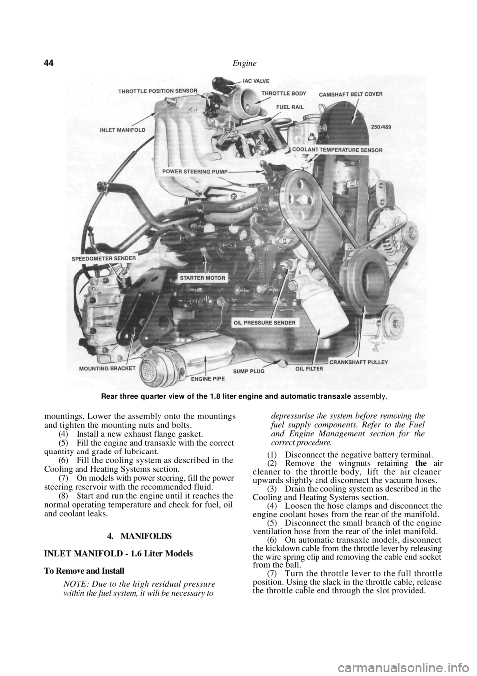
Rear three quarter view of the 1.8 liter engine and automatic transaxle assembly.
mountings. Lower the assembly onto the mountings
and tighten the mounting nuts and bolts.
(4) Install a new exhaust flange gasket.
(5) Fill the engine and transaxle with the correct
quantity and grade of lubricant. (6) Fill the cooling system as described in the
Cooling and Heating Systems section. (7) On models with power steering, fill the power
steering reservoir with the recommended fluid.
(8) Start and run the engine until it reaches the
normal operating temperatur e and check for fuel, oil
and coolant leaks.
4. MANIFOLDS
INLET MANIFOLD - 1.6 Liter Models
To Remove and Install
NOTE: Due to the high residual pressure
within the fuel system, it will be necessary to
depressurise the system before removing the
fuel supply components. Refer to the Fuel
and Engine Management section for the
correct procedure.
(1) Disconnect the negative battery terminal.
(2) Remove the wingnuts retaining the air
cleaner to the throttle body, lift the air cleaner
upwards slightly and disconnect the vacuum hoses. (3) Drain the cooling system as described in the
Cooling and Heating Systems section. (4) Loosen the hose clamps and disconnect the
engine coolant hoses from the rear of the manifold.
(5) Disconnect the small branch of the engine
ventilation hose from the rear of the inlet manifold. (6) On automatic transaxle models, disconnect
the kickdown cable from the throttle lever by releasing
the wire spring clip and re moving the cable end socket
from the ball.
(7) Turn the throttle lever to the full throttle
position. Using the slack in the throttle cable, release
the throttle cable end thr ough the slot provided.
Page 48 of 238
48 Engine
TO INSTAL
(1) Check that the camshaft and crankshaft
timing gears have not been moved and that the timing
marks are still aligned. It will be necessary to tempo-
rarily install the crankshaft pulley to check that the
timing marks are still aligned. (2) Install the drive belt to the crankshaft timing
gear around the water pump gear and onto the
camshaft timing gear.
NOTE: If the original drive belt is being
installed, ensure that the arrow marked on
the belt prior to removal is pointing in the
direction of rotation.
(3) Use the adjusting tool to turn the water
pump assembly sufficiently to engage the water pump
pulley with the drive belt. (4) Install the inner cover lower retaining bolt.
(5) Ensure that the drive be lt is correctly meshed
with the teeth of the camshaft, crankshaft and water
pump gears. Install the crankshaft pulley and tighten
the bolts to Specifications. (6) Adjust the drive belt as described under the
following heading.
(7) Install the drive belt outer cover and fasten
the retaining clips. (8) Install and adjust the alternator and if
equipped, the power steeri ng and air conditioning
drive belts as desc ribed in the Engine Tune-up section.
TO ADJUST
(1) Remove the alternator drive belt and if
equipped, the power steering and air conditioning
drive belts. (2) Release the clips securing the camshaft drive
belt outer cover to the inner cover and remove the
outer cover. (3) Turn the engine in the direction of rotation
until the timing marks on the camshaft and the inner
cover are aligned. (4) Loosen the water pump retaining bolts and
using the adjusting tool, rotate the water pump
housing to gain the required belt tension. The belt is
correctly tensioned when it can be grasped between
the thumb and forefinger midway between the cam-
shaft timing gear and the water pump gear and turned
ninety degrees from i t s operating position.
After the belt has been tensioned, tighten the
water pump retaining bolts to the specified torque.
NOTE: Over tensioning of the drive belt will
result in noisy operation and premature
wear of the belt.
(6) Install the outer drive belt cover.
(7) Install and adjust the alternator, and if
equipped, the power steering and air conditioning
drive belts as desc ribed in the Engine Tune-up section. 6. CAMSHAFT. ROCKER ARMS AND TAPPETS
Special Equipment Required:
To Check Camshaft — Dial gauge, Vee blocks and
micrometers
To Install — Drive belt adjusting tool
It is recommended that a new cylinder head
gasket is installed and the cylinder head bolts renewed
when the camshaft housing is removed.
TO REMOVE
(1) Disconnect the negative battery terminal.
Remove the nuts securing the earth wires to the
cylinder head bolts and remove the earth wires.
(2) On 1.6 liter models, remove the air cleaner
wingnuts and withdraw the air cleaner.
(3) Disconnect the engine breather hoses from
the camshaft housing and the camshaft housing top
cover. (4) Remove the camshaft housing top cover
retaining bolts and remove the top cover. Discard the
gasket.
(5) Remove the camshaft dr ive belt as described
under the previous heading. (6) Using an open ended spanner, hold the
camshaft between the inle t and exhaust lobes of
number four cylinder and remove the camshaft timing
gear retaining bolt and the camshaft timing gear.
(7) Remove the distributor, distributor cap and
high tension leads. If necessary refer to the Fuel and
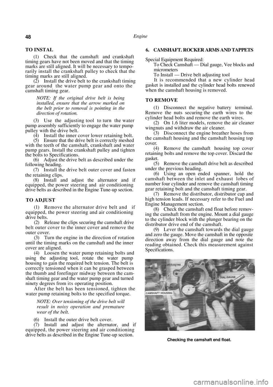
Engine Management section. (8) Check the camshaft end float before remov-
ing the camshaft from the engine. Mount a dial gauge
to the cylinder block with the plunger bearing on the
distributor drive end of the camshaft. (9) Lever the camshaft towards the dial gauge
and zero the gauge. Move the camshaft in the opposite
direction away from the dial gauge and note the
reading obtained. Check this measurement against
Specifications.
Checking the camshaft end float.
Page 70 of 238
70 Cooling and Heating Systems
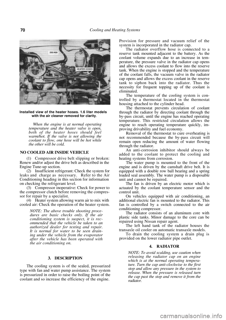
Installed view of the heater hoses. 1.6 liter models with the air cleaner removed for clarity
.
When the engine is at normal operating
temperature and the heater valve is open,
both of the heater hoses should feel
warm/hot. If the valve is not allowing the
coolant to flow, one hose will be hot while
the other will be cold.
NO COOLED AIR INSIDE VEHICLE
(1) Compressor drive belt slipping or broken:
Renew and/or adjust the drive belt as described in the
Engine Tune-up section.
(2) Insufficient refrigerant: Check the system for
leaks and charge as necessary. Refer to the Air
Conditioning heading in th is section for information
on checking the refrigerant level. (3) Compressor inoperative: Check for power to
the compressor clutch before removing the compres-
sor for repair by a specialist. (4) Heater system allowing warm air to mix with
cooled air: Check the operation of the heater system.
NOTE: The above trouble shooting proce-
dures are basic checks only. If the air
conditioning system is suspect, it is rec-
ommended that the vehicle be taken to an
authorized dealer for testing and repair.
It is normal for water to be seen drain-
ing under the vehicle from the evaporator
after the vehicle has been operated with
the air conditioning on.
3. DESCRIPTION
The cooling system is of the sealed, pressurized
type with fan and water pump assistance. The system
is pressurized in order to raise the boiling point of the
coolant and so increase the efficiency of the engine.
Provision for pressure a nd vacuum relief of the
system is incorporated in the radiator cap.
The radiator overflow hose is connected to a
reserve tank mounted adjacent to the battery. As the
coolant volume expands due to an increase in tem-
perature, the pressure valve in the radiator cap opens
and allows the excess coolant to flow into the reserve
tank. When the engine is stopped and the temperature
of the coolant falls, the vacuum valve in the radiator
cap opens and allows the excess coolant in the reserve
tank to siphon back into the radiator. Thus the
necessity for frequent topping up of the coolant is
eliminated.
The temperature of the cooling system is con-
trolled by a thermostat located in the thermostat
housing attached to the cylinder head.
The thermostat prevents circulation of coolant
through the radiator by directing coolant through the
by-pass circuit, until the engine has reached operating
temperature. This restricted circulation allows the
engine to reach operating temperature quickly, im-
proving drivability and fuel economy.
Removal of the thermostat to cure overheating is
not recommended because th e by-pass circuit will
remain open reducing the amount of water flowing
through the radiator.
An anti-corrosion inhibitor should always be
added to the coolant to protect the cooling and
heating systems from corrosion.
The water pump is mounted to the front of the
engine and is driven by the camshaft drive belt. It is
equipped with a double row ball bearing and a spring
loaded seal assembly. The water pump is a disposable
unit and cannot be repaired.
The fan is driven by an electric motor which is
actuated by the coolant temperature sensor and the
control unit.
On vehicles equipped with air conditioning, an
additional electric fan is m ounted to the radiator. This
fan is controlled by a sw itch connected to the air
conditioning compressor.
The radiator consists of an aluminum core with
plastic side tanks. Minor damage to the core can be
repaired using Nissan repair agent.
The left hand tank of the radiator houses the
transaxle oil cooler on automatic transaxle models.
To drain the cooling system a drain plug is
provided on the lower radiator pipe outlet.
4. RADIATOR
NOTE: To avoid scalding, use caution when
releasing the radiator cap on an engine
which is at the normal operating tempera-
ture. Turn the cap anti-clockwise to the first
stop and allow any pressure in the system to
release. When the pressure is released turn
the cap past the stop and remove it from the
radiator.