differential NISSAN PULSAR 1987 Workshop Manual
[x] Cancel search | Manufacturer: NISSAN, Model Year: 1987, Model line: PULSAR, Model: NISSAN PULSAR 1987Pages: 238, PDF Size: 28.91 MB
Page 3 of 238

CONTENTS
INTRODUCTION........................................ 5
VEHICLE IDENTIFICATION AND
GENERAL SPECIFICATIONS................. 7
GENERAL INFORMATION...................... 8
Tools and equipment ............................................. 8 Safety .................................................................... 10
General repair procedures..................................... 11
LUBRICATION AND MAINTENANCE... 14
Specifications......................................................... 14
How to grease and oil change .............................. 14
Service schedule ................................................... 17
WHEELS AND TYRES............................. 21
Specifications......................................................... 21
How to change a road wheel ................................ 21
Tire wear troubl e shooting ..................................... 22
Care and main tenance ......................................... 23
ENGINE TUNE-UP.................................... 25
Tune-up specifications ........................................... 25
Tune-up operat ions............................................... 25
ROADSIDE TROUBLE SHOOTING....... 32
Trouble shoot ing.................................................... 32
To check ignition and el ectrical system ................ 33
To check fuel system ............................................ 34
To check mechani cal system ................................ 35
ENGINE....................................................... 37
Specifications ........................................................ 37
Engine mechanical tr ouble shooting ...................... 39
Description ............................................................ 41
Engine and transaxle assembly ........................... 42
Manifolds ............................................................... 44 Camshaft, rocker arms and tappets..................... 48
Cylinder head........................................................ 50
Engine sump and oil pum p pickup pipe................ 54
Oil pump ............................................................... 55
Pistons, connecting rods and cylinder bores ........ 57
Crankshaft and bearings ...................................... 60
Flywheel /drive plate............................................... 63
Engine mountings.................................................. 64
Exhaust system .................................................... 66
COOLING AND HEATING SYSTEMS.... 68
Specifications ........................................................ 68 Cooling system trouble shooting ........................... 68
Heater and air conditioner trouble shooting ......... 69 Description ............................................................ 70
Radiator ................................................................ 70
Cooling fan ............................................................ 73
Thermost at............................................................ 75
Thermostat housing .............................................. 76
Water pump .......................................................... 76
Welch plugs .......................................................... 76
Heater unit, water valv e and controls ................... 77
Blower fan ............................................................. 80
Air condition ing ..................................................... 80
FUEL AND ENGINE MANAGEMENT ... 82
Specifications ........................................................ 82 Fuel and engine management trouble shooting ... 82
Description ............................................................ 84
Service precautions and procedures
..................... 86
System diagnosis and adjustments ...................... 89
Fuel supply components ....................................... 92
Air flow components .............................................. 98
Electronic components .......................................... 104
EMISSION CONTROL............................. 117
Introduction ........................................................... 117
Crankcase ventilati on system............................... 117
Evaporate control system..................................... 117
Air preheat system — 1.6 liter engines ................ 119
Exhaust control system ........................................ 120
CLUTCH...................................................... 121
Specifications........................................................ 121
Clutch trouble shooting......................................... 121
Description ............................................................ 122
Clutch unit and release mechanism..................... 123
Clutch pedal ......................................................... 124
Clutch c able.......................................................... 124
Clutch adjustments ............................................... 125
MANUAL TRANSAXLE AND
DRIVE SHAFTS......................................... 126
Specifications ........................................................ 126
Manual transaxle and drive shaft trouble shooting 126
Description............................................................ 128
Transaxle assembly.............................................. 129
Differential and final drive assembly ..................... 135
Gear lever assembly ............................................ 136
Drive shafts .......................................................... 137
AUTOMATIC TRANSAXLE....................... 140
Specifications........................................................ 140
Automatic transaxle trouble shooting.................... 140
Description............................................................ 141
Transaxle fluid ...................................................... 141
Brake band........................................................... 142
Kickdown cable .................................................... 142
Transaxle select or linkage ................................... 142
Neutral safety switch ............................................ 142
Transaxle assembly .............................................. 143
STEERING................................................. 145
PART 1. STEERING TROUBLE SHOOTING....145
Faults, causes and remedies................................ 145
PART 2. MANUA L STEERING......................... 147
Specifications ........................................................ 147
Description............................................................ 147
Steering wheel ...................................................... 147
Steering column.................................................... 148
Steering gear assembly ....................................... 149
PART 3. POWE R STEERING .......................... 152
Specifications........................................................ 152
Description............................................................ 152
In car adjustments, checks and minor repairs ..... 152
Steering wheel ...................................................... 153
Steering column.................................................... 153 Power steering pump ........................................... 153
Power steering gear assembly............................. 154
Page 5 of 238

INTRODUCTION
This Service and Repair Manual
covers the Australian manufac-
tured Nissan Pulsar (hatchback) and Vector (sedan) N13 Series 1
(J87 - 91 and
the Holden Astra LD Series 1987 - 89.
Two engines were available: a 1.8 l i t e r engine with multi-point fuel injec-
tion, and a 1.6 liter throttle body injected engine. The engines are similar
having single overhead camshafts and computer controlled fuel injection and
ignition control. There was a choice of three speed automatic or five speed
manual transaxles.
A viscous coupling limited s l i p differential was introduced from July 1989
to the five speed manual transaxle models of the Pulsar Q and Vector SSS.
Disc brakes are fitted at the front of a l l models, while the rear brakes are
either discs or drums.
All models are equipped with independent coil spring suspension. Steering
can be by either manual or power assisted rack and pinion.
This manual includes information on trouble shooting, lubrication and
maintenance, specifications and the rem oval, installation and overhaul of com-
ponents which are considered to be with in the scope of the average, well
equipped home mechanic.
Certain repair jobs covered in this manual require the use of special
equipment not normally found in a home tool kit. When such equipment is
required, the equipment and i t s functi on is brought to the users attention
underneath the heading for that component. Some jobs, such as automatic
transmission overhaul, should he left to an authorized dealer or a specialist
who has the extensive knowledge and equi pment required. In these cases, the
removal and installation procedures are fully covered, enabling the unit to be
removed for repair or a reconditioned unit to be installed.
Reference in the manual to the left an d right hand sides of the vehicle are
from the point of view of someone sta nding at the back of the vehicle and
looking forward.
Inexperienced operators should not a ttempt a service or repair operation
before completely reading the appropriat e section (or other sections which may
be referred to) in the manual.
Page 126 of 238
126
MANUAL TRANSAXLE AND DRIVE SHAFTS
SPECIFICATIONS
TRANSAXLE
Type .....................................Five speed, synchromesh
on all forward gears
Model .......................................................... RS5F31A
Gear ratios: 1.6 liter -
First .......................................................... 3.333:1
Second...................................................... 1.955:1
Third......................................................... 1.286:1
Fourth....................................................... 0.975:1
Fifth.......................................................... 0.810:1
Reverse .................................................... 3.417:1
1.8 liter -
First .......................................................... 3.063:1
Second...................................................... 1.826:1
Third......................................................... 1.286:1
Fourth ....................................................... 0.975:1
Fifth.......................................................... 0.810:1
Reverse .................................................... 3.417:1
Gear end float:
Fifth...............................................0.18-0.41 mm
Second, third and fourth................0.20-0.40 mm
First ...............................................0.18-0.31 mm
Synchro ring to gear clearance:
Standard ............................................ 1.0-1.3 mm
Minimum ................................................. 0.7 mm
Turning torque (new bearings):
Differential assembly ........................ 3.9-7.8 Nm
Total differential and mainshaft __ 5.9-13.7 Nm
Differential and final drive:
Type ........................ Helical ring gear and pinion
Ratio......................................................... 4.167:1
Lubricant:
Grade ............................................. 80W-90 GL-4
Capacity ..................................................2.7 liters
DRIVE SHAFTS
C.V. joint lubrication:
Lubricant ........ Valvoline Special Moly EP grease
Amount ................................................. 40 grams
TORQUE WRENCH SETTINGS
Transaxle case retaining bolts ........
Cover plate to transaxle case .......................... 8.3 Nm
Input shaft bearing retainer bolts ..................... 21 Nm
Control bracket bolts ...................................... 8.3 Nm
Reverse check plug.......................................... 25 Nm
Ring gear to differential case........................... 88 Nm
Filler and drain plugs....................................... 34 Nm
Reverse lamps switch ...................................... 29 Nm
Upper and centre clutch housing to engine…...49 Nm
Lower clutch housing to engine ...................... 21 Nm
1. MANUAL TRANSAXLE AND DRIVE
SHAFT
TROUBLE SHOOTING
DIFFICULT GEAR CHANGE
(1) Faulty clutch or clutch release mechanism:
Check and adjust or overhaul the clutch or the clutch
release mechanism. (2) Loose control bracket retaining bolts: Dis-
mantle the transaxle and tighten the control bracket
retaining bolts. Apply Loctite or an equivalent to the
bolt threads to prevent a repeat of the problem.
(3) Faulty gear lever assembly: Check and
renew
or repair the gear lever assembly. (4) Bent or worn gear lever control rod: Repair
or renew the faulty components. (5) Worn transaxle selector mechanism: Over-
haul the transaxle assembly. Renew components as
necessary.
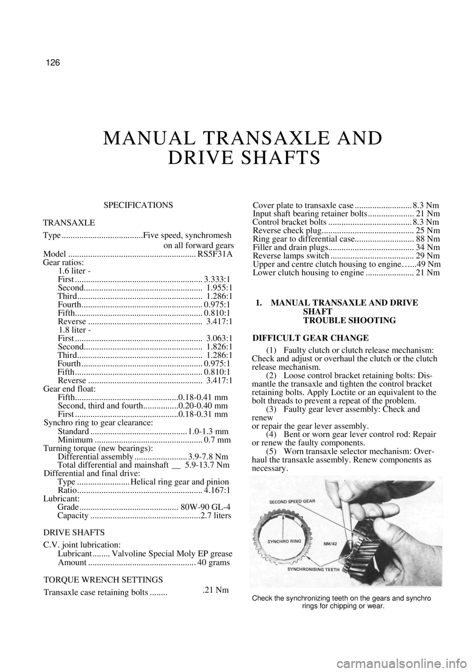
.21 NmCheck the synchronizing teeth on the gears and synchro
rings for chipping or wear.
Page 128 of 238
128 Manual Transaxle and Drive Shafts
TRANSAXLE NOISE (FORWARD GEARS
ENGAGED, VEHICLE MOVING)
(1) Insufficient lubricant: Fill the transaxle with
the correct grade and quantity of oil. (2) Worn input shaft or mainshaft bearings:
Overhaul the transaxle and renew the faulty bearings. (3) Chipped or pitted gears: Check and overhaul
the transaxle and renew the faulty gears. (4) Damaged or worn sync hroniser assemblies:
Overhaul the transaxle and renew the synchroniser
assemblies.
FINAL DRIVE GEAR NOISE
(1) Insufficient lubricant: Fill the transaxle case
with the correct grade and quantity of oil. (2) Chipped or pitted final drive gear and/or ring
gear: Overhaul the transaxle and renew components as
necessary. (3) Worn differential carrier bearings: Overhaul
the differential assembly.
(4) Worn mainshaft or input shaft bearings:
Overhaul the transaxle.
NOTE: Check the oil level in the transaxle
case and the condition of the front hub
bearings and drive shaft joints prior to
overhauling the transaxle.
EXCESSIVE BACKLASH IN FINAL DRIVE
(1) Excessive end float in the differential carrier
bearings due to worn or incorrect bearing preload
adjustment: Check and adjust the bearing preload or
renew the bearings.
(2) Ring gear to differential case bolts loose:
Overhaul the transaxle and tighten the bolts to the
specified torque.
(3) Excessive wear in the final drive gear: Check
and overhaul the transaxle. (4) Excessive wear in the differential pinions,
side gears or pinion shaft: Overhaul the differential
assembly.
NOTE: Prior to overhauling the differential,
check the serviceability of the C.V joints on
the drive shafts.
NO DRIVE IN ANY GEAR
(1) Sheared ring gear to differential case bolts:
Overhaul the differential assembly.
(2) Broken drive shaft: Check and renew com-
ponents as necessary.
(3) Inner C.V. joint shaft out of mesh with
differential side gear: Weak or broken inner C.V. joint
shaft snap ring. Renew as necessary.
NOISE OR VIBRATION IN DRIVE SHAFTS
( 1 ) Bent or twisted drive shafts: Check and
renew the drive shafts as necessary.
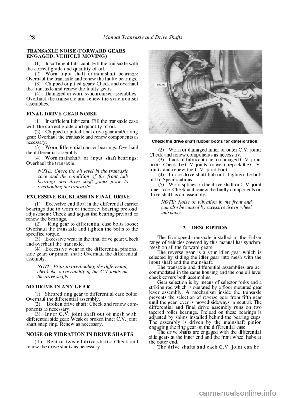
Check the drive shaft rubber boots for deterioration.
(2) Worn or damaged inner or outer C.V. joint:
Check and renew components as necessary. (3) Lack of lubricant due to damaged C.V. joint
boots: Check the C.V. joints for wear, repack the C. V.
joints and renew th e C.V. joint boot.
(4) Loose drive shaft hub nut: Tighten the hub
nut to Specifications. (5) Worn splines on the drive shaft or C.V. joint
inner race. Check and renew the faulty components or
drive shaft as an assembly.
NOTE: Noise or vibration in the front end
can also be caused by excessive tire or wheel
unbalance.
2. DESCRIPTION
The five speed transaxle installed in the Pulsar
range of vehicles covered by this manual has synchro-
mesh on all the forward gears.
The reverse gear is a spur idler gear which is
selected by sliding the idler gear into mesh with the
input shaft and the mainshaft.
The transaxle and differential assemblies are ac-
commodated in the same housing and the one oil level
check covers both assemblies.
Gear selection is by mean s of selector forks and a
striking rod which is operated by a floor mounted gear
lever assembly. A mechanism inside the transaxle
prevents the selection of re verse gear from fifth gear
until the gear lever is moved sideways in neutral. The
differential and final dr ive assembly runs on two
tapered roller bearings. Pr eload on these bearings is
adjusted by shims installed behind the bearing cups.
The assembly is driven by the mainshaft pinion
engaging the ring gear on the differential case.
The drive shafts are engaged with the differential
side gears at the inner end and the front wheel hubs at
the outer end.
The drive shafts and each C.V. joint can be
Page 129 of 238
Manual Transaxle and Drive Shafts 129
renewed as individual units. The C.V. joints are
lubricated in manufacture and need no attention in
service unless one of the r ubber boots is damaged. In
this case the joint can be cl eaned and repacked with
the recommended grease and a new boot installed.
From July 1989, Pulsar Q and Vector SSS manual
transaxle models are equipped with a limited slip
differential incorporating a viscous coupling. The
coupling is not repairable and must be renewed as an
assembly if unserviceable. A test procedure for the
viscous coupling is included in the text in this section.
3. TRANSAXLE ASSEMBLY
Special Equipment Required:
To Dismantle and Assemble — Puller set, press
and press plates, dial gauge
To Measure Mainshaft Turning Torque —
Suitable slotted adaptor and torque gauge
TO REMOVE AND INSTAL
(1) Raise the front of the vehicle and support it
on chassis stands.
(2) Remove the battery as described in the
Electrical System section. (3) Remove the drive shafts as described later in
this section. (4) Disconnect and remove the starter motor as
described in the Elect rical System section.
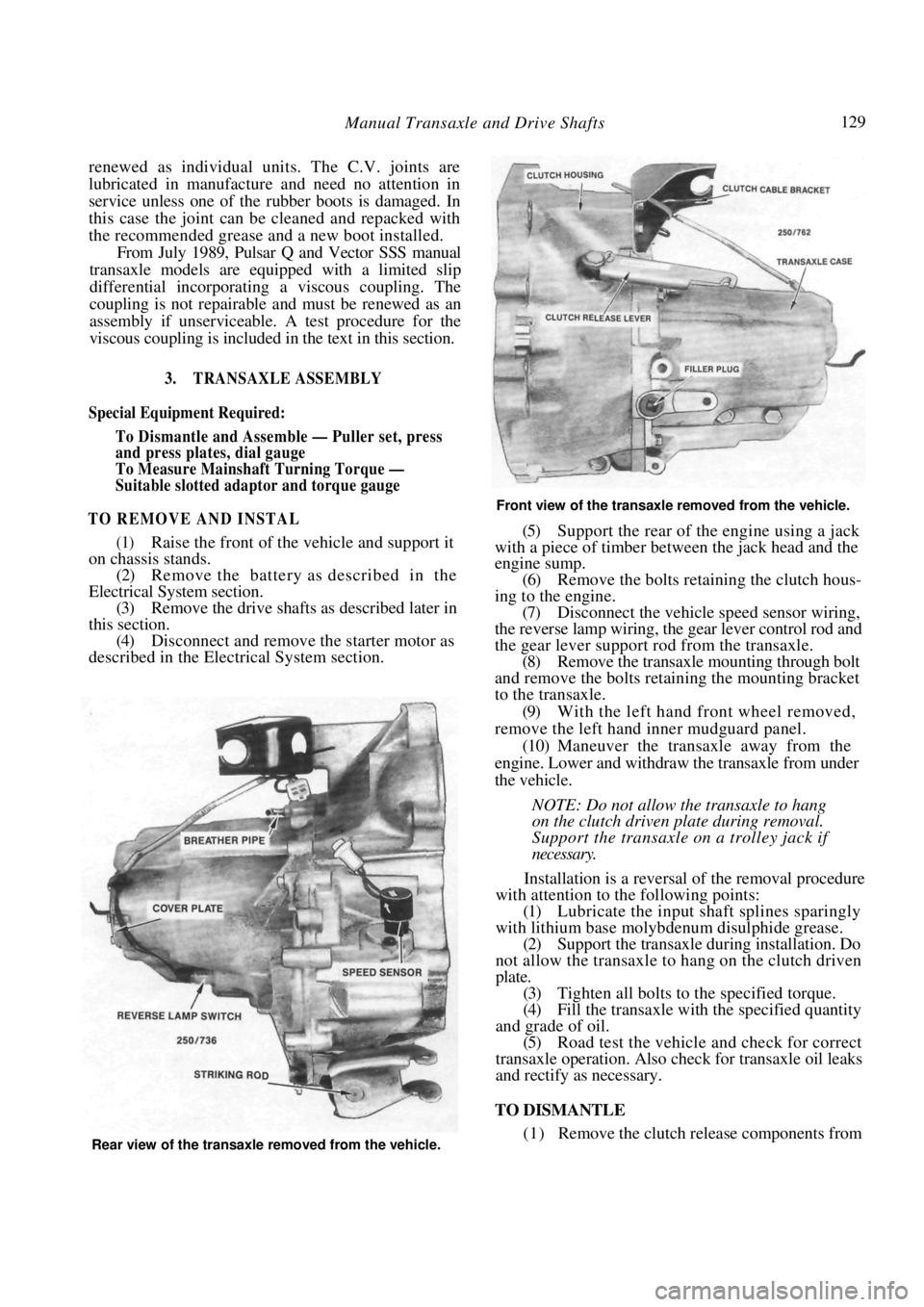
Front view of the transaxle removed from the vehicle.
(5) Support the rear of the engine using a jack
with a piece of timber between the jack head and the
engine sump.
(6) Remove the bolts retaining the clutch hous-
ing to the engine. (7) Disconnect the vehicle speed sensor wiring,
the reverse lamp wiring, the gear lever control rod and
the gear lever support rod from the transaxle. (8) Remove the transaxle mounting through bolt
and remove the bolts retaining the mounting bracket
to the transaxle.
(9) With the left hand front wheel removed,
remove the left hand inner mudguard panel. (10) Maneuver the transaxle away from the
engine. Lower and withdraw the transaxle from under
the vehicle.
NOTE: Do not allow the transaxle to hang
on the clutch driven plate during removal.
Support the transaxle on a trolley jack if
necessary.
Installation is a reversal of the removal procedure
with attention to the following points:
(1) Lubricate the input shaft splines sparingly
with lithium base molybdenum disulphide grease. (2) Support the transaxle during installation. Do
not allow the transaxle to hang on the clutch driven
plate. (3) Tighten all bolts to the specified torque.
(4) Fill the transaxle with the specified quantity
and grade of oil. (5) Road test the vehicle and check for correct
transaxle operation. Also ch eck for transaxle oil leaks
and rectify as necessary.
TO DISMANTLE
(1) Remove the clutch release components from Rear view of the transaxle removed from the vehicle.
Page 130 of 238
130 Manual Transaxle and Drive Shafts
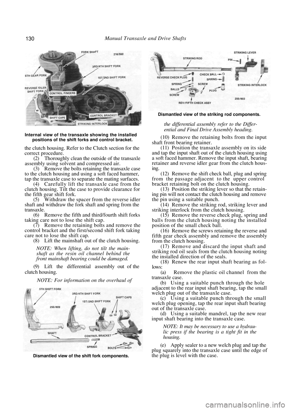
Internal view of the transaxle showing the installed positions of the shift forks and control bracket.
the clutch housing. Refer to the Clutch section for the
correct procedure.
(2) Thoroughly clean the outsi de of the transaxle
assembly using solvent and compressed air. (3) Remove the bolts retaining the transaxle case
to the clutch housing and using a soft faced hammer,
tap the transaxle case to separate the mating surfaces.
(4) Carefully lift the transaxle case from the
clutch housing. Tilt the cas e to provide clearance for
the fifth gear shift fork. (5) Withdraw the spacer from the reverse idler
shaft and withdraw the fork shaft and spring from the
transaxle. (6) Remove the fifth and third/fourth shift forks
taking care not to lose the shift cap. (7) Remove the retaining bolts and remove the
control bracket and the first/second shift fork taking
care not to lose the shift cap. (8) Lift the mainshaft out of the clutch housing.
NOTE: When lifting, do not tilt the main-
shaft as the resin oil channel behind the
front mainshaft bearing could be damaged.
(9) Lift the differential assembly out of the
clutch housing.
NOTE: For information on the overhaul of
Dismantled view of the striking rod components.
the differential assembly refer to the Differ-
ential and Final Drive Assembly heading.
(10) Remove the retaining bolts from the input
shaft front bearing retainer. (11) Position the transaxle assembly on its side
and tap the input shaft out of the clutch housing using
a soft faced hammer. Remove the input shaft, bearing
retainer and reverse idler gear from the clutch hous-
ing.
(12) Remove the shift check ball, plug and spring
from the passage adjacent to the upper control
bracket retaining bolt on the clutch housing.
(13) Position the striking lever so that the retain-
ing pin will not contact the clutch housing and remove
the pin using a suitable punch.
(14) Remove the striking rod, striking lever and
striking interlock from the clutch housing.
(15) Remove the reverse check plug, spring and
balls from the clutch housing noting the installed
position of the small check ball.
(16) Remove the screws retaining the reverse and
fifth gear check assembly and remove the assembly
from the clutch housing.
(17) Remove and discard the input shaft and
striking rod oil seals from the clutch housing noting
the installed direction of the seals.
(18) Renew the rear input shaft bearing as fol-
lows:
(a) Remove the plastic oil channel from the
transaxle case.
(b) Using a suitable punch through the hole
adjacent to the r ear input shaft bearing, tap the small
welch plug out of the transaxle case.
(c) Using a suitable punch through the small
welch plug opening, tap the rear input shaft bearing
out of the transaxle case. (d) Using a suitable mandrel, tap the new rear
input shaft bearing into the transaxle case.
NOTE: It may be necessary to use a hydrau-
lic press if the bearing is a tight fit in the
housing.
(e) Apply sealer to a new welch plug and tap the
plug squarely into the transaxle case until the edge of
the plug is level with the case.
Dismantled view of the shift fork components.
Page 133 of 238
Manual Transaxle and Drive Shafts 133
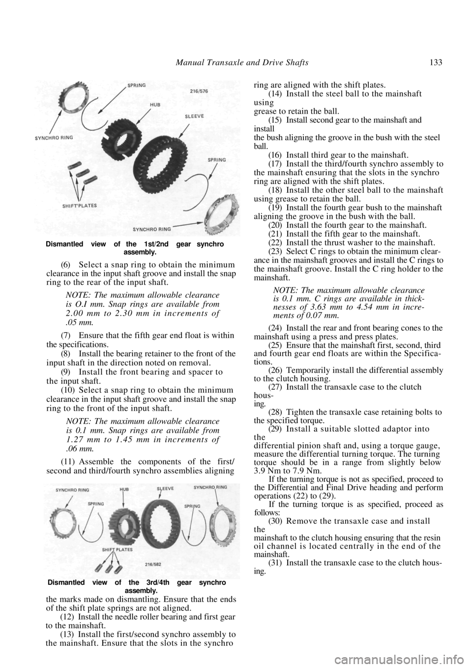
Dismantled view of the 1st/2nd gear synchro assembly.
(6) Select a snap ring to obtain the minimum
clearance in the input shaft groove and install the snap
ring to the rear of the input shaft.
NOTE: The maximum allowable clearance
is O.I mm. Snap rings are available from
2.00 mm to 2.30 mm in increments of
.05 mm.
(7) Ensure that the fifth gear end float is within
the specifications. (8) Install the bearing retain er to the front of the
input shaft in the direction noted on removal.
(9) Install the front bearing and spacer to
the input shaft. (10) Select a snap ring to obtain the minimum
clearance in the input shaft groove and install the snap
ring to the front of the input shaft.
NOTE: The maximum allowable clearance
is 0.1 mm. Snap rings are available from
1.27 mm to 1.45 mm in increments of
.06 mm.
(11) Assemble the components of the first/
second and third/fourth sy nchro assemblies aligning
the marks made on dismantling. Ensure that the ends
of the shift plate springs are not aligned.
(12) Install the needle roller bearing and first gear
to the mainshaft.
(13) Install the firs t/second synchro assembly to
the mainshaft. Ensure that the slots in the synchro ring are aligned with the shift plates.
(14) Install the steel ball to the mainshaft
using
grease to retain the ball. (15) Install second gear to the mainshaft and
install
the bush aligning the groove in the bush with the steel
ball. (16) Install third gear to the mainshaft.
(17) Install the third/fourth synchro assembly to
the mainshaft ensuring that the slots in the synchro
ring are aligned with the shift plates.
(18) Install the other steel ball to the mainshaft
using grease to retain the ball. (19) Install the fourth gear bush to the mainshaft
aligning the groove in the bush with the ball. (20) Install the fourth gear to the mainshaft.
(21) Install the fifth gear to the mainshaft.
(22) Install the thrust washer to the mainshaft.
(23) Select C rings to obtain the minimum clear-
ance in the mainshaft grooves and install the C rings to
the mainshaft groove. Install the C ring holder to the
mainshaft.
NOTE: The maximum allowable clearance
is 0.1 mm. C rings are available in thick-
nesses of 3.63 mm to 4.54 mm in incre-
ments of 0.07 mm.
(24) Install the rear and front bearing cones to the
mainshaft using a press and press plates. (25) Ensure that the mainshaft first, second, third
and fourth gear end floats are within the Specifica-
tions.
(26) Temporarily install the differential assembly
to the clutch housing. (27) Install the transaxle case to the clutch
hous-
ing. (28) Tighten the transaxle case retaining bolts to
the specified torque. (29) Install a suitable slotted adaptor into
the
differential pinion shaft a nd, using a torque gauge,
measure the differential tu rning torque. The turning
torque should be in a range from slightly below
3.9 Nm to 7.9 Nm. If the turning torque is not as specified, proceed to
the Differential and Final Drive heading and perform
operations (22) to (29).
If the turning torque is as specified, proceed as
follows:
(30) Remove the transaxle case and install
the
mainshaft to the clutch housing ensuring that the resin
oil channel is located centrally in the end of the
mainshaft. (31) Install the transaxle case to the clutch hous-
ing.
Dismantled view of the 3rd/4th gear synchro
assembly.
Page 134 of 238

134 Manual Transaxle and Drive Shafts
(32) Install and tighten the retaining bolts to
the specified torque.
(33) Repeat operation (29). The total turning
torque should be 5.9-13.7 Nm if new bearings have
been installed or slightly l ess if the original bearings
have been installed. If the turning torque is no t as specified, adjust the
mainshaft turning torque as follows:
(a) Remove the transaxle case rear cover, O ring,
spacer and adjusting shim from the transaxle case.
(b) Ensure that the mainsh aft rear bearing outer
race is fully seated on the bearing cone. (c) Using micrometer depth gauge, measure the
distance from the transaxle case to the bearing outer
race and note the reading. (d) Referring to the following table, select the
appropriate shim, according to the reading noted in
operation (c), required to correct the mainshaft turn-
ing torque.
READING SHIM
2.35-2.40 mm............................................... 0.10 mm
2.40-2.45 mm............................................... 0.15 mm
2.45-2.50 mm...............................................0.20 mm
2.50-2.55 mm...............................................0.25 mm
2.55-2.60 mm...............................................0.30 mm
2.60-2.65 mm............................................... 0.35 mm
2.65-2.70 mm............................................... 0.40 mm
2.70-2.75 mm............................................... 0.45 mm
2.75-2.80 mm............................................... 0.50 mm
2.80-2.85 mm............................................... 0.55 mm
2.85-2.90 mm............................................... 0.60 mm
2.90-2.95 mm............................................... 0.65 mm
2.95-3.00 mm............................................... 0.70 mm
3.00-3.05 mm............................................... 0.75 mm
3.05-3.10 mm............................................... 0.80 mm
3.10-3.15 mm............................................... 0.85 mm
3.15-3.20 mm............................................... 0.90 mm
3.20-3.25 mm............................................... 0.95 mm
3.25-3.30 mm...............................................1.00 mm.
(e) Install the spacer, shim, O ring and rear
cover to the transaxle case. Tighten the retaining
bolts securely.
(34) Measure the total turning torque as previ-
ously described. (35) Install the striking interlock and striking lever
to the clutch housing. (36) Install the striking ro d to the clutch housing
sliding the rod through the lever and interlock. Take
care that the end of the rod does not damage the seal. (37) Install a new retaining pin to the striking rod
using a pin punch. (38) Install the reverse and fifth gear check
assembly to the clutch housing. Tighten the retaining
screws securely. (39) Install the balls, spring and reverse check
plug to the clutch housing ensuring that the smaller
diameter ball enters the hole in the body of the
reverse and fifth gear check assembly body. Apply locking com-
pound and tighten the reverse check plug securely.
(40) Using a bar clamped to the end of the
striking rod, check that a force of 4.9-7.4 Nm is
required to overcome the spring loading of the reverse
and fifth gear check assembly. If necessary, renew the
springs to achieve this correct spring loading.
NOTE: Ensure that the reverse check plug is
coated with locking compound when finally
installed.
(41) Install the shift check ball, spring and plug to
the clutch housing. Ensure that the ball is centrally
located in the plug.
(42) If removed, install the oil reservoir to the
clutch housing.
(43) Install the input shaft assembly and the
reverse idler gear to the clutch housing taking care not
to damage the seal.
(44) Apply locking compound to the bearing
retainer bolts and tighten the bolts to the specified
torque.
(45) Install the spacer to the reverse idler shaft.
(46) Install the differential assembly to the clutch
housing.
(47) Install the mainshaft to the clutch housing
ensuring that the resin oil ch annel is located centrally
in the end of the mainshaft. (48) Install the shift cap to the slot in the first/
second shift fork and install the shift fork and control
bracket to the clutch housing. Use grease to hold the
shift cap in the shift fork slot. Ensure that the reverse
idler shift fork is correctly located over the gear.
(49) Apply locking compound to the threads of
the control bracket retaining bolts and tighten the
bolts to the specified torque. (50) Install the shift cap in the slot in the third/
fourth shift fork and install the fork to the transaxle
assembly. Use grease to hold the shift cap in the shift
fork slot. (51) Install the fifth gear shift fork to the transaxle
ensuring that the shift fork slot engages the control
finger.
(52) Install the fork shaft an d spring to the clutch
housing sliding the shaft through the shift forks. Use
grease to hold the spring in the end of the shaft. (53) Apply a continuous bead of sealant to the
mating face of the clutch housing so that the bead is
located inside the row of bolt holes.
NOTE: Sealant is available from Nissan
spare parts using the part number KP
610-00250.
(54) Install the transaxle case to the clutch hous-
ing. Install and tighten the retaining bolts to the
specified torque. (55) Select each gear in turn and check that the
transaxle turns freely in each gear. Ensure that it is not
Page 135 of 238
Manual Transaxle and Drive Shafts 135
possible to move the striking rod from fifth gear to
reverse without first moving sideways in the neutral
gate.
4. DIFFERENTIAL AND FINAL DRIVE ASSEMBLY
Special Equipment Required:
To Measure Differential Turning Torque —
Suitable slotted adaptor and torque gauge
TO CHECK VISCOUS COUPLING
From July 1989, Manual transaxle Pulsar Q and
Vector SSS models are equipped with a limited slip
differential incorporating a viscous coupling.
(1) Raise the front of the vehicle and support it
on chassis stands. (2) Rotate one front wheel and check the rota-
tional direction of the opposite wheel. (3) If both front wheels rotate in the same
direction, the viscous coupling is functioning nor-
mally. (4) If the front wheels rota te in opposite direc-
tions, the viscous coupling is unserviceable and must
be renewed as an assembly.
TO DISMANTLE AND ASSEMBLE
It is necessary to remove and dismantle the
transaxle assembly to gain access to the differential
and final drive assembly.
Refer to the Transaxle Assembly heading for the
removal of the transaxle from the vehicle. Operations
1-9 of the dismantling procedure under the same
heading describe the removal of the differential and
final drive assembly from the transaxle.
(1) If necessary, cut and remove the speedome-
ter drive gear from the differential case. (2) Using a suitable puller, remove the differen-
tial carrier bearing cone and roller assemblies from the
differential case and remove the speedometer drive
gear stopper.
(3) Remove the ring gear retaining bolts and
separate the ring gear from the differential case using
a soft faced hammer.
(4) Using a pin punch, remove the retaining pin
from the differential pinion shaft.
(5) Remove the pinion shaft from the differen-
tial case. (6) Remove the pinion gears and thrust washers
from the differential case. (7) Remove the side gears and spacers from the
differential case.
NOTE: If applicable, the viscous coupling is
integral with the left hand side gear.
(8) Wash all the differential components with
cleaning solvent. (9) Check the gears, spacer s, thrust washers,
pinion shaft and differential case for wear, pitting and
damage. Renew parts as necessary.
(10) Install the side gears and spacers to
the
differential case.
(11) Install the pinion gear s and thrust washers
to
the differential case.
(12) Install the pinion shaft to the differential case
aligning the retaining pin hole. (13) Install the retaining pin to the pinion shaft
until the end of the pin is level with the differential
case. (14) With a dial gauge contacting the end of the
side gear, lift the side gear evenly and measure the
clearance between the side gear and the differential
case. The clearance should be 0.1-0.2 mm.
NOTE: Do not tilt the side gear or the dial
gauge reading will be incorrect.
(15) If necessary, adjust the side gear clearance
using selective fit spacers.
NOTE: Spacers are available from 0.15 mm
to 1.00 mm in increments of 0.05 mm.
(16) Measure and if necessary, adjust the other
side gear clearance. (17) On models equipped with a viscous cou-
pling, adjust the side gear clearance as follows:
(a) Temporarily secure the differential case with
two bolts. (b) Position the differential case so that the right
hand side gear is uppermost. (c) Insert a 0.03 mm feeler gauge between the
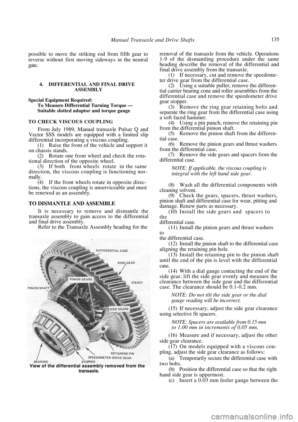
View of the differential ass embly removed from the
transaxle.
Page 136 of 238

136 Manual Transaxle and Drive Shafts
right hand side gear and the adjacent spacer in an area
where there is no oil groove in the differential case.
(d) Insert another 0.03 mm feeler gauge diago-
nally opposite the first feeler gauge to avoid tilting the
side gear.
(e) Insert a splined adaptor into the right hand
side gear and attempt to rotate the gear by hand.
(f) If the gear cannot be rotated, change the
thickness of the left hand side gear spacer, repeating
the test until the gear can be rotated.
NOTE: Spacers are available in thicknesses
from 0.8 mm to 1.5 mm in increments of
0.1 mm.
(g) Remove the 0.03 mm feel er gauges and insert
0.09 mm feeler gauges to the same position. The gear
should lock.
(h) The spacer selection is correct when the right
hand side gear can be rotated with 0.03 mm feeler
gauges inserted but locks when 0.09 mm feeler gauges
are inserted.
(18) Install the ring gear to the differential case
with the chamfered edge of the ring gear inwards. (19) Install and tighten the retaining bolts in
a
diagonal sequence to the specified torque.
(20) Install a new speedometer drive gear to
the
differential case. Install the stopper adjacent to the
drive gear.
(21) Install the differentia] carrier bearing
cones
and roller assemblies to the differential case.
(22) Remove the adjusting shim from behind the
carrier bearing outer race in the transaxle case and
replace the outer race in the transaxle case.
(23) Install the differential assembly to the clutch
housing. (24) Install the transaxle case to the clutch housing
and tighten the retaining bolts to the specified torque.
(25) Mount a dial gauge to the clutch housing so
that the contact point is resting on the differential
case. (26) Insert a bar through the opposite side gear
and, contacting the pinion shaft, raise and lower the
differential case and measure the end float in the
carrier bearings. (27) Using the following table, select a shim to
correspond to the relevant end float.
END FLOAT SHIM THICKNESS
0.30-0.34 mm....................................................0.64 mm
0.34-0.38 mm................................................... 0.68 mm
0.38-0.42 mm................................................... 0.72 mm
0.42-0.46 mm................................................... 0.76 mm
0.46-0.50 mm................................................... 0.80 mm
0.50-0.54 mm................................................... 0.84 mm
0.54-0.58 mm................................................... 0.88 mm
0.58-0.62 mm................................................... 0.92 mm
0.62-0.66 mm................................................... 0.96 mm
0.66-0.70 mm................................................... 1.00 mm
0.70-0.74 mm................................................... 1.04 mm
0.74-0.78 mm ................................................... 1.08 mm
0.78-0.82 mm ................................................... 1.12 mm
0.82-0.86 mm ................................................... 1.16 mm
0.86-0.90 mm ................................................... 1.20 mm
0.90-0.94 mm ................................................... 1.24 mm
0.94-0.98 mm ................................................... 1.28 mm
0.98-1.02 mm ................................................... 1.32 mm
1.02-1.06 mm ................................................... 1.36 mm
1.06-1.10 mm ................................................... 1.40 mm
1.10-1.14 mm ................................................... 1.44 mm
1.14-1.18 mm ................................................... 1.48 mm
1.18-1.22 mm ................................................... 1.52 mm
1.22-1.26 mm ................................................... 1.56 mm
1.26-1.30 mm ................................................... 1.60 mm
1.30-1.34 mm ................................................... 1.64 mm
1.34-1.38 mm ................................................... 1.68 mm
1.38-1.42 mm ................................................... 1.72 mm
1.42-1.46 mm ................................................... 1.76 mm
The thickest shim available is 0.88 mm. Multiple
shims are required above this thickness.
(28) Install the shim behind the carrier
bearing
outer race in the transaxle case and assemble the unit
once more. (29) Using a suitable slotted adaptor engage the
pinion shaft and using a to rque gauge, measure the
differential turning torque. The turning torque when new carrier bearings
have been installed should be 3.9-7.8 Nm or slightly
lower if the original carrier bearings have been
replaced.
(30) Assemble the transaxle and measure the total
turning torque of the diff erential assembly and the
mainshaft. The total turning torque should be 5.9 to
13.7 Nm with new bearings or slightly lower if the
original bearings have been replaced.
5. GEAR LEVER ASSEMBLY
TO DISMANTLE AND ASSEMBLE
(1) Remove the gear lever knob and remove the
centre console as described in the Body section. If not
previously removed, remove the rubber boot sur-
rounding the gear lever. (2) Raise the front of the vehicle and support it
on chassis stands. Remove the catalytic converter and
heat shield as described in the Engine section.
(3) Remove the bolt and disconnect the control
rod from the bottom of the gear lever, noting the
position of the return spring and bracket.
(4) Remove the nuts retaining the gear lever
socket to the support rod. (5) Working inside the vehicle, lift the gear lever
out of the floor bracket. (6) Separate the lower rubber boot, socket,
spring seat, spring, upper ball seat and lower ball seat
from the gear lever, noting the location of each
component to aid assembly.