turn signal NISSAN PULSAR 1987 Workshop Manual
[x] Cancel search | Manufacturer: NISSAN, Model Year: 1987, Model line: PULSAR, Model: NISSAN PULSAR 1987Pages: 238, PDF Size: 28.91 MB
Page 4 of 238

FRONT SUSPENSION............................ 156
Specifications......................................................... 156
Front suspension tr ouble shooting ........................ 156
Description ............................................................ 157
Steering knuckle.................................................... 157
Suspension unit..................................................... 159
Control arm ........................................................... 161
Stabiliser bar ........................................................ 162
Suspension and steering angles .......................... 163
REAR SUSPENSION................................ 164
Specifications ........................................................ 164
Rear suspension tr ouble shooting ........................ 164
Description ............................................................ 165
Rear hub ............................................................... 166
Suspension unit .................................................... 167
Control arm ........................................................... 169
Knuckle assembly.................................................. 170
Stabiliser bar ........................................................ 170
Rear wheel alignment ........................................... 171
BRAKES...................................................... 172
Specifications......................................................... 172
Brakes trouble shooting ........................................ 172
Description ............................................................ 174
Master cyli nder...................................................... 175
Brake servo unit .................................................... 177
Front brakes ......................................................... 178
Rear disc brakes................................................... 181
Rear drum brakes ................................................. 184
Handbrake cable and le ver assembly ................... 186
Brake adjustments ................................................ 187
Brake pedal ........................................................... 187
Hydraulic system................................................... 188
ELECTRICAL SYSTEM............................ 190
Specifications......................................................... 190
Battery and charging system trouble shooting ....... 190
Battery and starting system trouble shooting ........ 191
Lighting system trouble shooting ........................... 192
Turn signal lamp trouble shooting ........................ 192
Test equipment and so me applications................. 193
Battery ................................................................... 194
Alternator ............................................................... 196
Starter motor ......................................................... 201
Ignition system ...................................................... 206
Steering wheel ....................................................... 206
Switches and controls........................................... 206
Instrument cluster.................................................. 209
Blower fan .............................................................. 209
Radio/cassette...................................................... 209
lamp units ............................................................ 210
Windscreen wiper ................................................. 213
Fuses, fusible links and relays ............................. 215
Trailer wiring ......................................................... 216
Wiring diagrams ................................................... 218
BODY........................................................... 225
Windscreen and re ar glass .................................. 225
Front doors ........................................................... 225
Rear doors............................................................ 228
Engine bonnet...................................................... 231
Tailgate and lock — hatchback ............................ 231
Luggage compartment lid and lock — sedan ........ 233
Radiator grille.............................................................. 234
Centre console...................................................... 234 Dashboard ............................................................ 235
Scat belts ............................................................. 236
Seats .................................................................... 236
Vehicle cleaning ........................................................... 237
CONVERSION TABLES.......................... 238
Page 85 of 238

Fuel and Engine Management 85
View of the 1.6 liter engine showing the engine management components. Air cleaner removed for clarity.
series of tests on various components in the system
and records the results, If a fault is discovered, the
ECM warning lamp on the instrument cluster will
illuminate while the engine is running. When the self
diagnosis mode is activated, the ECM warning lamp
will flash codes indicating the area in which the fault
has occurred.
This function is very useful in locating system
faults, particularly intermittent problems. However,
the self diagnosis mode does not provide comprehen-
sive testing of the EFI system, and therefore should
always be used in conjunction with the other test
procedures described later in this section in order to
accurately locate system faults.
The high energy electronic ignition system con-
sists of a distributor and an ignition coil.
The distributor has two functions. The first is to
produce and distribute secondary high tension voltage
to the spark plugs.
The second function is to provide the control unit
with information on engine speed and crankshaft
position.
The ignition timing is constantly adjusted by the
control unit to suit varying engine and vehicle oper-
ating conditions.
In the fuel injection system, a metered amount of
fuel is sprayed into the air stream. The air/fuel
mixture then enters the combustion chamber via the
inlet valves.
On 1.6 liter engines, the fuel is injected by a single
injector, located above the throttle valve within the
throttle body assembly. The injector fires twice per
engine revolution under most operating conditions.
On 1.8 liter engines, four injectors are used. The
fuel is distributed to the injectors via the fuel rail. All
injectors fire simultaneous ly once per engine revolu-
tion under most operating conditions.
Under conditions of high load the control unit
may signal the injector(s) to fire more often. However,
if the engine speed exceeds 6 700 rpm the control unit
will cease firing the injectors until the engine speed is
below 6 200 rpm.
Fuel is supplied under pressu re by an electric fuel
pump mounted in the fuel tank and the pressure is
regulated by a pressure regulator.
On 1.6 liter engines, the regulator consists of a
spring tensioned diaphragm which is mounted to the
side of the throttle body assembly. The fuel pressure is
regulated by the tension of the spring against the
diaphragm, opening and closing the fuel return port.
On 1.8 liter engines, the pressure regulator is
mounted adjacent to the fuel rail and consists of a
diaphragm with fuel pressu re acting on one side and
spring tension and manifold vacuum acting on the
Page 104 of 238
104 Fuel and Engine Management
(3) Gently pull the outer throttle cable until the
inner cable remains taut without moving the throttle
linkage. (4) Install the snap ring into the groove
posi-
tioned second from the insulator.
(5) Depress the throttle pedal and check that the
throttle valve opens fully and returns to the idle
position when the pedal is released. (6) On 1.6 liter engines, install the air
cleaner
assembly.
7. ELECTRONIC COMPONENTS
NOTE: Before proceeding with any of the
operations in this section, refer to the Ser-
vice Precautions and Procedures heading.
TO CHECK IGNITION SYSTEM
(1) Perform the test procedure described in the
Roadside Trouble Shooting section. Repair or renew
components as necessary. (2) Perform the self diagnosis test procedure as
previously described and rectify any faults. If there is
no spark, proceed as follows. (3) Disconnect the 4 pin wiring connector from
the distributor and check for spark at a spark plug
high tension lead using the test spark plug. If there is a spark, renew the pickup coil in the
distributor.
If there is no spark, proceed as follows.
(4) Connect the coil high tension lead to the test
spark plug and check for spark.
If there is a spark, check the distributor cap and
rotor for cracks and moisture. Repair or renew as
necessary.
If there is no spark, proceed as follows.
(5) Disconnect the 2 pin wiring connector from
the distributor. (6) With the ignition switched On. measure the
voltage at terminals A and B on the distributor 2 pin
wiring connector. If the voltage at terminal B only is under 10 volts,
check the wiring harness for continuity between
terminal B on the distributor 2 pin wiring connector
and terminal 2 on the black ignition coil wiring
connector. Repair or renew the wiring harness as
necessary. If no fault is found, renew the ignition coll.
If the voltages at both terminals is under 10 volts,
check the wiring harness between terminal A on the
distributor 2 pin wiring connector and terminal 1 on
the black ignition coil wiring connector for continuity.
Also check the fuel pump fuse and the wiring harness
between the ignition switch and the ignition coil.
Repair or renew the wiring harness as necessary.
If the voltage at both terminals is 10 volts or
more, proceed as follows.
(7) Connect the 2 pin wiring connector to the
distributor. (8) With the ignition switched On, measure the
voltage at the tachometer signal wire.
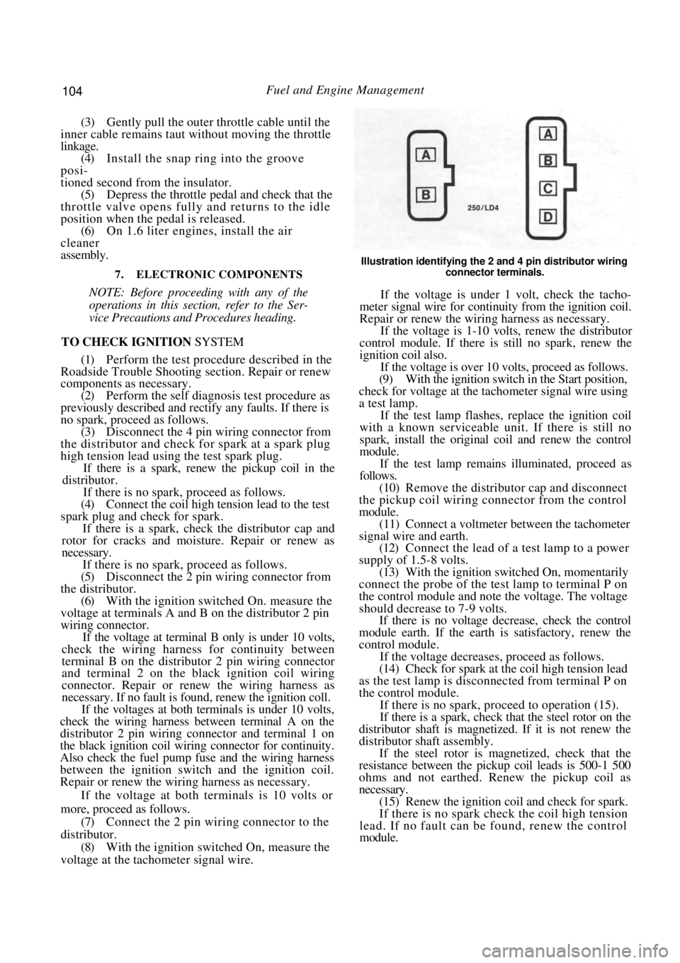
Illustration identifying the 2 and 4 pin distributor wiring
connector terminals.
If the voltage is under 1 volt, check the tacho-
meter signal wire for continuity from the ignition coil.
Repair or renew the wiring harness as necessary.
If the voltage is 1-10 volts, renew the distributor
control module. If there is still no spark, renew the
ignition coil also.
If the voltage is over 10 volts, proceed as follows.
(9) With the ignition switch in the Start position,
check for voltage at the tachometer signal wire using
a test lamp.
If the test lamp flashes, replace the ignition coil
with a known serviceable un it. If there is still no
spark, install the original coil and renew the control
module.
If the test lamp remains illuminated, proceed as
follows.
(10) Remove the distributor cap and disconnect
the pickup coil wiring co nnector from the control
module. (11) Connect a voltmeter between the tachometer
signal wire and earth. (12) Connect the lead of a test lamp to a power
supply of 1.5-8 volts. (13) With the ignition switched On, momentarily
connect the probe of the test lamp to terminal P on
the control module and note the voltage. The voltage
should decrease to 7-9 volts. If there is no voltage decrease, check the control
module earth. If the earth is satisfactory, renew the
control module.
If the voltage decreases , proceed as follows.
(14) Check for spark at the coil high tension lead
as the test lamp is disconnected from terminal P on
the control module.
If there is no spark, proceed to operation (15).
If there is a spark, check that the steel rotor on the
distributor shaft is magnetized. If it is not renew the
distributor shaft assembly.
If the steel rotor is magnetized, check that the
resistance between the pickup coil leads is 500-1 500
ohms and not earthed. Renew the pickup coil as
necessary.
(15) Renew the ignition coil and check for spark.
If there is no spark check the coil high tension
lead. If no fault can be found, renew the control
module.
Page 116 of 238

116 Fuel and Engine Management
Rear view of the instrument cluster showing the flexible printed circuit.
If the voltage is under 5 volts proceed as follows.
(17) Check the wiring harness for continuity or
shorts to earth between th e red wire terminal on the
speed sensor harness connector and the green and
black wire terminal on th e instrument cluster wiring
connector.
If no fault can be found check the instrument
cluster printed circuit for continuity or shorts. If no
fault can be found, renew the speedometer and the
signal divider circuit board.
(18) Remove the instrument cluster as described
in the Electrical System se ction and repeat operation
(16).
If the voltage is under 1 volt, check the flexible
printed circuit on the rear of the instrument cluster for
continuity or shorts and re new as necessary. If no fault
can be found, renew the speedometer and the signal
divider circuit board.
(19) Connect the harness connector to the vehicle
speed sensor wiring connector. (20) Raise the front of the vehicle and support it on chassis stands. Place the transaxle in Neutral.
(21) With the aid of assistants, slowly spin the
front wheels by hand while backprobing the brown
wire terminal on the vehicle speed sensor wiring
connector with a voltmeter to earth.
The voltage should alternate between approxi-
mately 1 and 7 volts.
If the voltage is as specif ied, check the flexible
printed circuit on the rear of the instrument cluster for
continuity or shorts. If no fault can be found, renew
the speedometer and the signal divider circuit board.
If the voltage is not as specified, proceed as
follows.
(22) Disconnect the vehicle speed sensor wiring
connector and unscrew the sensor from the speedom-
eter drive housing. (23) Rotate both front wheels in the same direc-
tion and check that the speedometer drive shaft is
turning and does not slip. If the drive shaft does not operate as described,
renew the drive assembly as described in the Manual
or Automatic Transaxle section.
If the drive shaft operates satisfactorily, renew the
vehicle speed sensor.
To Remove and Install
(1) Disconnect the negative battery terminal.
(2) Disconnect the vehicle speed sensor wiring
connector. (3) Unscrew the vehicle speed sensor from the
speedometer drive housing.
Installation is a reversal of the removal procedure
with attention to the following points:
(1) Align the cut-out in the speedometer drive
shaft with the notch in the vehicle speed sensor shaft.
(2) Tighten the vehicle speed sensor securely.
Page 147 of 238
147
PART 2. MANUAL STEERING
SPECIFICATIONS
Steering gear type ............................ Rack and pinion
Steering column type ...................... Energy absorbing
collapsible and tilt adjustable
Steering wheel free play
(maximum ) ...................................................... 35 mm
Linkage........................... Direct from rack ends to t i e
rods and steering knuckles
Turns lock to lock ................................................. 3.6
Steering column length .................. 534.7-537.3 mm
Steering gear lubricant.............. Castrol EPL 1 grease
TORQUE WRENCH SETTINGS
Steering wheel retaining nut ............................ 39 Nm
Steering gear to bulkhead
mounting bolts .............................................. 108 Nm
Tie rod to steering knuckle nut...................... 98 Nm
Tie rod to tie rod end locknut ....................... 98 Nm
Tie rod ball housing to rack............................ 88 Nm
Steering column to mounting
bracket bolt ...................................................... 14 Nm
Steering column universal
coupling joint pinch bolts ............................... 29 Nm
2. STEERING WHEEL
Special Equipment Required:
To Remove Steering Wheel - Steering wheel
puller
TO REMOVE AND INSTAL
(1) Disconnect the negative battery terminal.
(2) Using a small screwdriver, carefully prise the
centre ornament from the steering wheel.
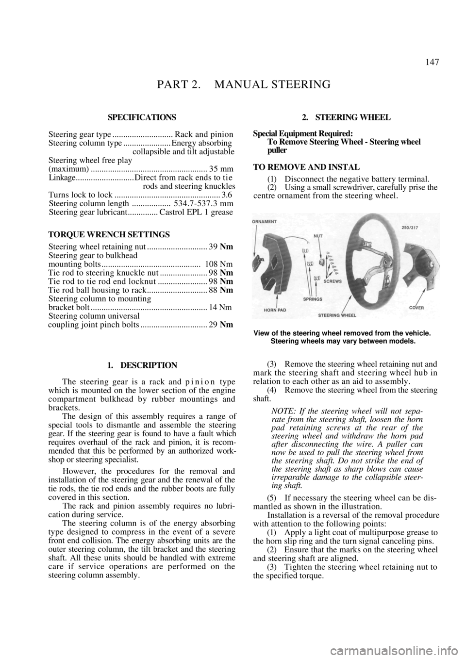
View of the steering wheel removed from the vehicle.
Steering wheels may vary between models.
1. DESCRIPTION
The steering gear is a rack and p i n i o n type
which is mounted on the lower section of the engine
compartment bulkhead by rubber mountings and
brackets.
The design of this assembly requires a range of
special tools to dismantle and assemble the steering
gear. If the steering gear is found to have a fault which
requires overhaul of the rack and pinion, it is recom-
mended that this be performed by an authorized work-
shop or steering specialist.
However, the procedures for the removal and
installation of the steering gear and the renewal of the
tie rods, the tie rod ends and the rubber boots are fully
covered in this section.
The rack and pinion assembly requires no lubri-
cation during service.
The steering column is of the energy absorbing
type designed to compress in the event of a severe
front end collision. The energy absorbing units are the
outer steering column, the tilt bracket and the steering
shaft. All these units shoul d be handled with extreme
care if service operations are performed on the
steering column assembly.
(3) Remove the steering wh eel retaining nut and
mark the steering shaft and steering wheel hub in
relation to each other as an aid to assembly.
(4) Remove the steering wheel from the steering
shaft.
NOTE: If the steering wheel will not sepa-
rate from the steering shaft, loosen the horn
pad retaining screws at the rear of the
steering wheel and withdraw the horn pad
after disconnecting the wire. A puller can
now be used to pull the steering wheel from
the steering shaft. Do not strike the end of
the steering shaft as sharp blows can cause
irreparable damage to the collapsible steer-
ing shaft.
(5) If necessary the steering wheel can be dis-
mantled as shown in the illustration.
Installation is a reversal of the removal procedure
with attention to the following points:
(1) Apply a light coat of multipurpose grease to
the horn slip ring and the turn signal canceling pins.
(2) Ensure that the marks on the steering wheel
and steering shaf t are aligned.
(3) Tighten the steering wheel retaining nut to
the specified torque.
Page 192 of 238
192 Electrical System
transaxle models, check for a faulty or incorrectly
adjusted neutral safety switch.
1. Discharged battery: Check for a fault or short
circuit in the system. 2. Battery fully charged but will not crank
engine. Check for a locked drive and ring gear,
internal starter faul t or seized engine.
3. Fusible link blown: Check and repair the
cause and renew as necessary.
NOTE: Rotate the engine by hand to ensure
that the starter drive is not locked with the
flywheel ring gear and t hat the engine is not
seized. Ensure that the ignition key is
turned off before rotating the engine.
3. LIGHTING SYSTEM TROUBLE SHOOTING
LAMP OR LAMPS FAIL TO LIGHT
1. Faulty bulb(s): Check and renew the faulty
bulb(s). 2. Open circuit in the wiring or connections:
Check the lamp circuits and rectify as necessary.
1. Faulty lamp switch: Check and if necessary
renew the lamp switch. 2. Faulty fuse or fuse connection: Repair the
fuse connection or renew the fuse. 3. Lamp relay faulty: Check and renew as
necessary.
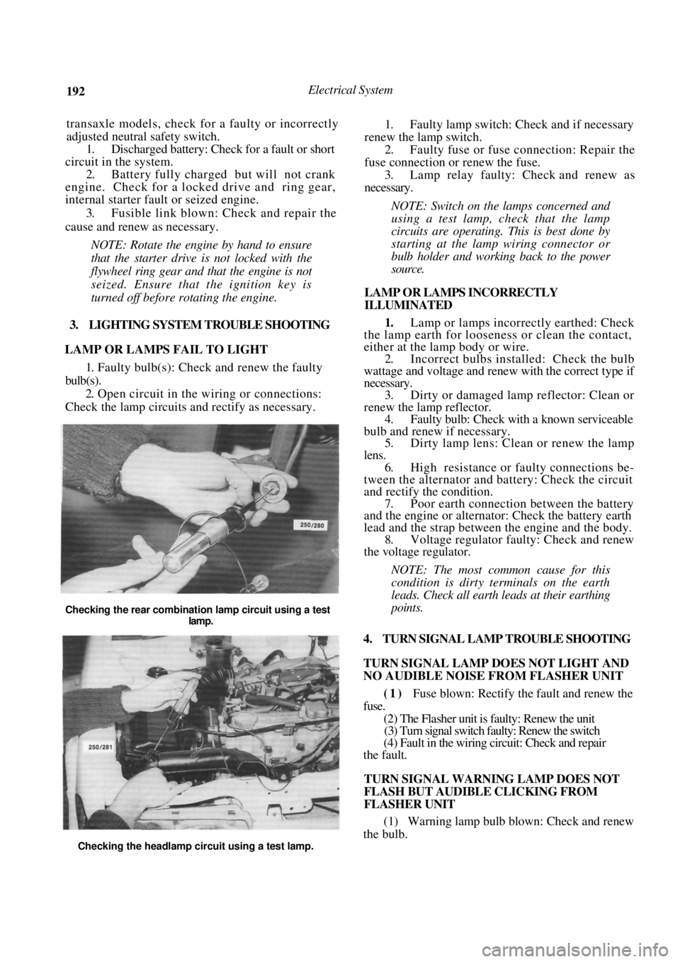
NOTE: Switch on the lamps concerned and
using a test lamp, check that the lamp
circuits are operating. This is best done by
starting at the lamp wiring connector or
bulb holder and work ing back to the power
source.
LAMP OR LAMPS INCORRECTLY
ILLUMINATED
1. Lamp or lamps incorrectly earthed: Check
the lamp earth for loosene ss or clean the contact,
either at the lamp body or wire.
2. Incorrect bulbs installe d: Check the bulb
wattage and voltage and renew with the correct type if
necessary. 3. Dirty or damaged lamp reflector: Clean or
renew the lamp reflector. 4. Faulty bulb: Check with a known serviceable
bulb and renew if necessary. 5. Dirty lamp lens: Clean or renew the lamp
lens. 6. High resistance or faulty connections be-
tween the alternator and battery: Check the circuit
and rectify th e condition.
7. Poor earth connection between the battery
and the engine or alternat or: Check the battery earth
lead and the strap between the engine and the body. 8. Voltage regulator faulty: Check and renew
the voltage regulator.
NOTE: The most common cause for this
condition is dirty t erminals on the earth
leads. Check all earth leads at their earthing
points.
4. TURN SIGNAL LAMP TROUBLE SHOOTING
TURN SIGNAL LAMP DOES NOT LIGHT AND
NO AUDIBLE NOISE FROM FLASHER UNIT
(1) Fuse blown: Rectify the fault and renew the
fuse.
(2) The Flasher unit is faulty: Renew the unit
(3) Turn signal switch faulty: Renew the switch
(4) Fault in the wiring circuit: Check and repair
the fault.
TURN SIGNAL WARNING LAMP DOES NOT
FLASH BUT AUDIBLE CLICKING FROM
FLASHER UNIT
(1) Warning lamp bulb blown: Check and renew
the bulb.
Checking the rear combination lamp circuit using a test
lamp.
Checking the headlamp circuit using a test lamp.
Page 193 of 238
Electrical System 193
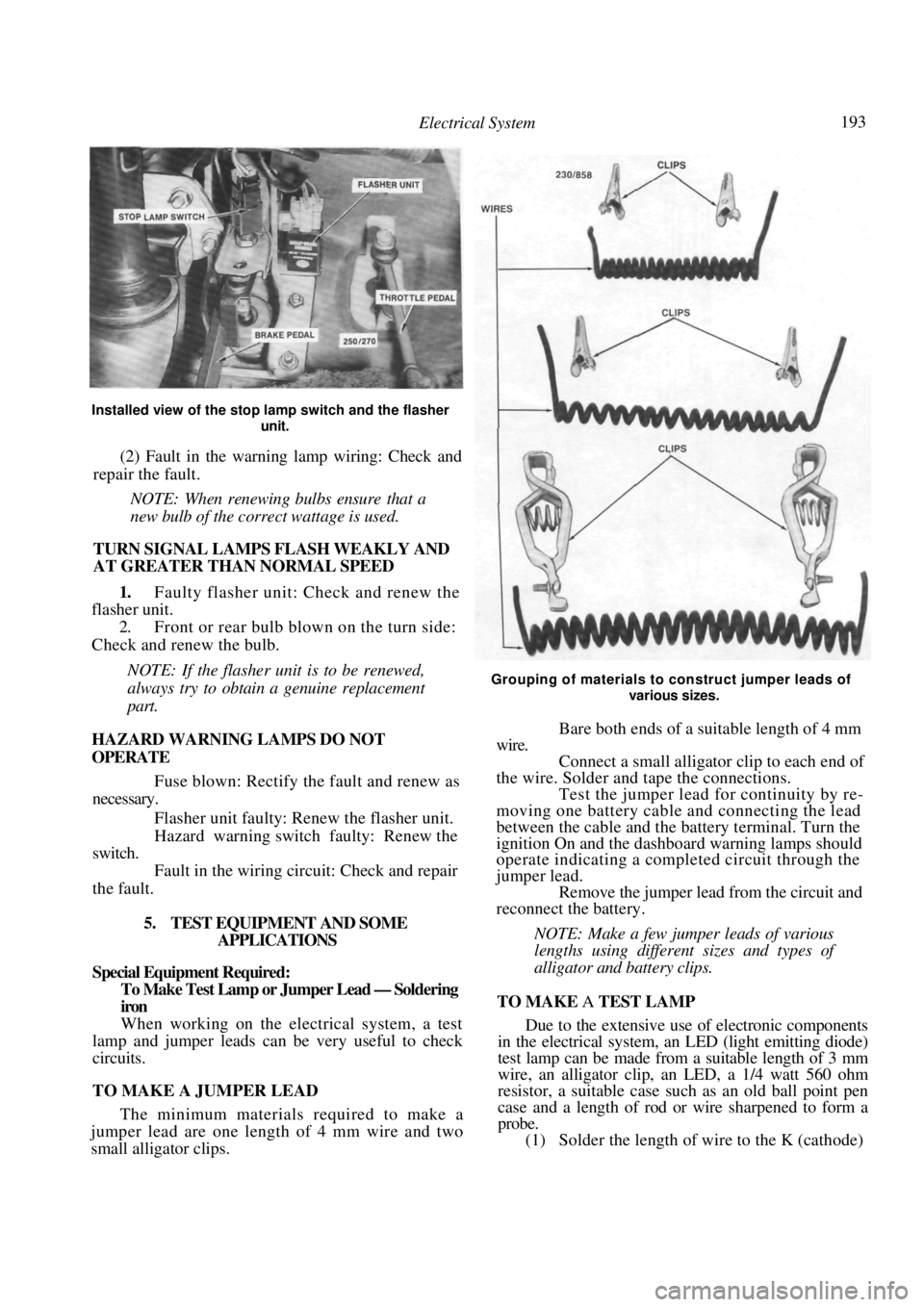
Installed view of the stop lamp switch and the flasher
unit.
(2) Fault in the warning lamp wiring: Check and
repair the fault.
NOTE: When renewing bulbs ensure that a
new bulb of the correct wattage is used.
TURN SIGNAL LAMPS FLASH WEAKLY AND
AT GREATER THAN NORMAL SPEED
1. Faulty flasher unit: Check and renew the
flasher unit.
2. Front or rear bulb blown on the turn side:
Check and renew the bulb.
NOTE: If the flasher unit is to be renewed,
always try to obtain a genuine replacement
part.
HAZARD WARNING LAMPS DO NOT
OPERATE
Fuse blown: Rectify the fault and renew as
necessary.
Flasher unit faulty: Re new the flasher unit.
Hazard warning switch faulty: Renew the
switch.
Fault in the wiring circuit: Check and repair
the fault.
5. TEST EQUIPMENT AND SOME APPLICATIONS
Special Equipment Required:
To Make Test Lamp or Jumper Lead — Soldering
iron
When working on the electrical system, a test
lamp and jumper leads can be very useful to check
circuits.
TO MAKE A JUMPER LEAD
The minimum materials required to make a
jumper lead are one length of 4 mm wire and two
small alligator clips.
Grouping of materials to construct jumper leads of
various sizes.
Bare both ends of a suitable length of 4 mm
wire. Connect a small alligato r clip to each end of
the wire. Solder and tape the connections. Test the jumper lead for continuity by re-
moving one battery cable and connecting the lead
between the cable and the battery terminal. Turn the
ignition On and the dashboard warning lamps should
operate indicating a completed circuit through the
jumper lead. Remove the jumper lead from the circuit and
reconnect the battery.
NOTE: Make a few jumper leads of various
lengths using different sizes and types of
alligator and battery clips.
TO MAKE A TEST LAMP
Due to the extensive use of electronic components
in the electrical system, an LED (light emitting diode)
test lamp can be made from a suitable length of 3 mm
wire, an alligator clip, an LED, a 1/4 watt 560 ohm
resistor, a suitable case such as an old ball point pen
case and a length of rod or wire sharpened to form a
probe.
(1) Solder the length of wire to the K (cathode)
Page 206 of 238
206 Electrical System
Install the armature and yoke to the drive end
bracket rotating the drive to align the reduction gears.
Do not use force.
Install the retaining through bolts to the
commutator end bracket and lighten the through bolts
and armature end cover retaining screws securely. Install the solenoid to the drive end bracket,
install the retaining screws and tighten them securely.
Install the brush connector strap and
install
the retaining nut and washer and tighten securely.
9 . IGNITION SYSTEM
The testing and repair procedures for the ignition
system are fully covered in the Fuel and Engine
Management section.
10. STEERING WHEEL
The removal and installation procedures for the
steering wheel and horn pad are fully covered in the
Steering section.
11. SWITCHES AND CONTROLS
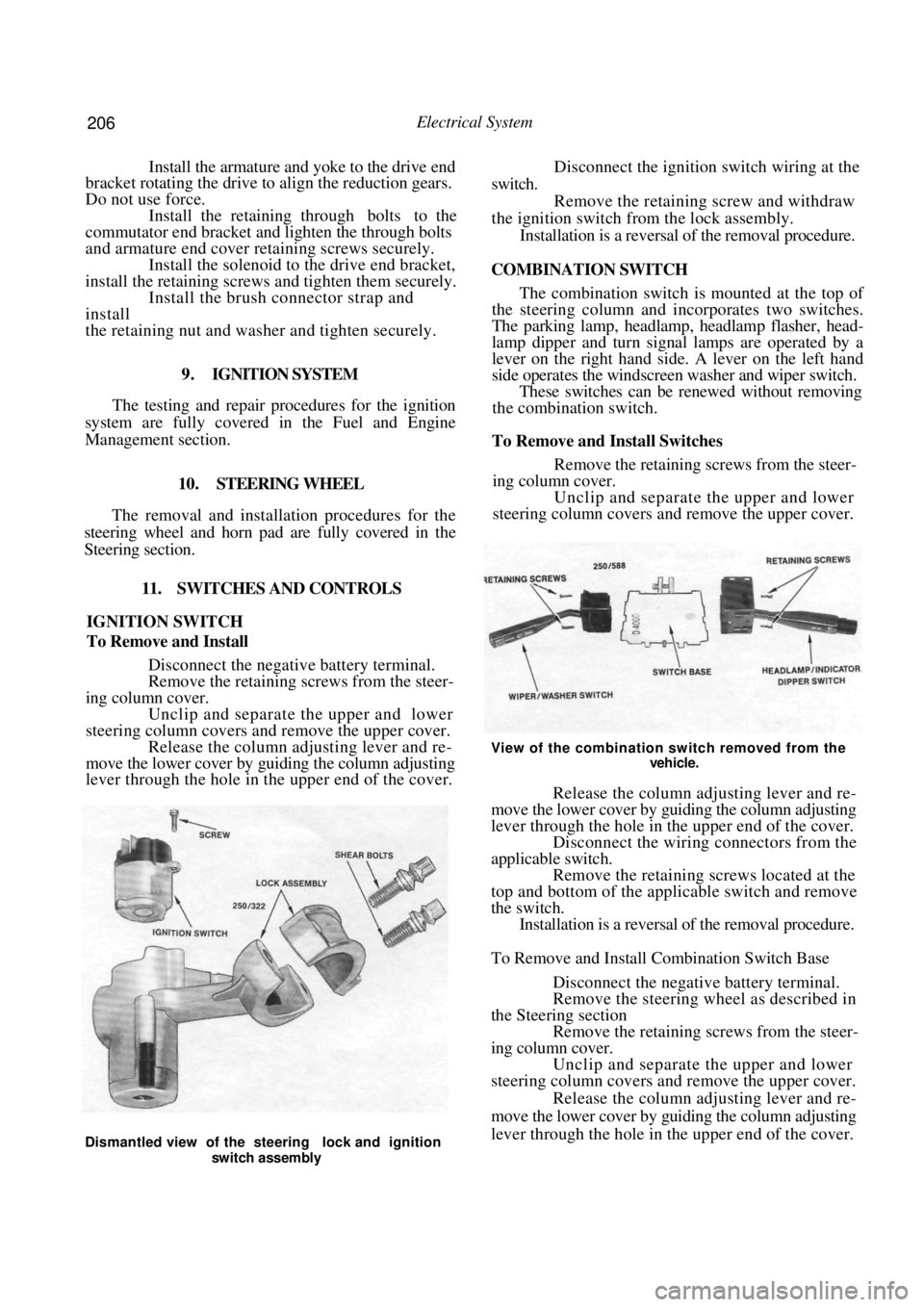
IGNITION SWITCH
To Remove and Install
Disconnect the negative battery terminal.
Remove the retaining screws from the steer-
ing column cover. Unclip and separate the upper and lower
steering column covers and remove the upper cover. Release the column adjusting lever and re-
move the lower cover by guiding the column adjusting
lever through the hole in the upper end of the cover.
Disconnect the ignition switch wiring at the
switch. Remove the retaining screw and withdraw
the ignition switch fr om the lock assembly.
Installation is a reversal of the removal procedure.
COMBINATION SWITCH
The combination switch is mounted at the top of
the steering column and incorporates two switches.
The parking lamp, headlamp, headlamp flasher, head-
lamp dipper and turn signal lamps are operated by a
lever on the right hand side. A lever on the left hand
side operates the windscreen washer and wiper switch.
These switches can be re newed without removing
the combination switch.
To Remove and Install Switches
Remove the retaining screws from the steer-
ing column cover.
Unclip and separate the upper and lower
steering column covers and remove the upper cover.
View of the combination switch removed from the
vehicle.
Release the column adjusting lever and re-
move the lower cover by guiding the column adjusting
lever through the hole in the upper end of the cover. Disconnect the wiring connectors from the
applicable switch. Remove the retaining screws located at the
top and bottom of the applicable switch and remove
the switch. Installation is a reversal of the removal procedure.
To Remove and Install Combination Switch Base
Disconnect the negative battery terminal.
Remove the steering wheel as described in
the Steering section Remove the retaining screws from the steer-
ing column cover. Unclip and separate the upper and lower
steering column covers and remove the upper cover.
Release the column adjusting lever and re-
move the lower cover by guiding the column adjusting
lever through the hole in the upper end of the cover.
Dismantled view of the steering lock and ignition
switch assembly
Page 211 of 238
Electrical System 211
When using an aiming board, position the
vehicle five meters from and square to the aiming
board. Gently rock the vehi cle and allow the suspen-
sion to stabilize. Mark a reference line on the board to
correspond with the horizontal centre line of the
headlamp low beam bulbs. Mark two reference lines on the board to
correspond with the vertical centre lines of
the
headlamp low beam bulbs. Switch on the headlamps and select low
beam. Adjust the headlamps by turning the adjust-
ing screws located at the rear of the headlamp
assemblies. Adjust the headlamps to comply with local
regulations. As a guide, adjust the lamps so that the
low beam pattern strikes the aiming board with the
horizontal cut off point 50 mm below the headlamp
bulb horizontal centre line and the point where the
beam raises from the horizontal is on the headlamp
low beam bulb vertical centre line.
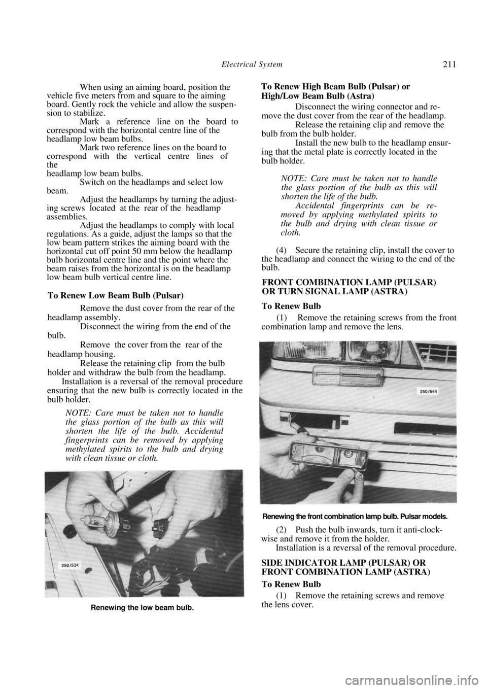
To Renew Low Beam Bulb (Pulsar)
Remove the dust cover from the rear of the
headlamp assembly.
Disconnect the wiring from the end of the
bulb.
Remove the cover from the rear of the
headlamp housing. Release the retaining clip from the bulb
holder and withdraw the bulb from the headlamp. Installation is a reversal of the removal procedure
ensuring that the new bulb is correctly located in the
bulb holder.
NOTE: Care must be taken not to handle
the glass portion of the bulb as this will
shorten the life of the bulb. Accidental
fingerprints can be removed by applying
methylated spirits to the bulb and drying
with clean tissue or cloth.
To Renew High Beam Bulb (Pulsar) or
High/Low Beam Bulb (Astra) Disconnect the wiring connector and re-
move the dust cover from the rear of the headlamp. Release the retaining clip and remove the
bulb from the bulb holder. Install the new bulb to the headlamp ensur-
ing that the metal plate is correctly located in the
bulb holder.
NOTE: Care must be taken not to handle
the glass portion of the bulb as this will
shorten the life of the bulb.
Accidental fingerprints can be re-
moved by applying methylated spirits to
the bulb and drying with clean tissue or
cloth.
(4) Secure the retaining clip, install the cover to
the headlamp and connect the wiring to the end of the
bulb.
FRONT COMBINATION LAMP (PULSAR)
OR TURN SIGNAL LAMP (ASTRA)
To Renew Bulb
(1) Remove the retaining screws from the front
combination lamp and remove the lens.
Renewing the front combination lamp bulb. Pulsar models.
(2) Push the bulb inwards, turn it anti-clock-
wise and remove it from the holder. Installation is a reversal of the removal procedure.
SIDE INDICATOR LAMP (PULSAR) OR
FRONT COMBINATION LAMP (ASTRA)
To Renew Bulb
(1) Remove the retaining screws and remove
the lens cover.
Renewing the low beam bulb.
Page 217 of 238
Electrical System 217
When installing a trailer socket, it may be neces-
sary to replace the original vehicle flasher unit with a
heavy duty unit to maintain the flash rate in accor-
dance with local regulations. Local regulations may
also require the installation of a dashboard mounted
repeater lamp.
Should the trailer socket and plug not be matched,
adaptors can be made or obtained to facilitate con-
nection.
TO INSTAL TRAILER SOCKET.
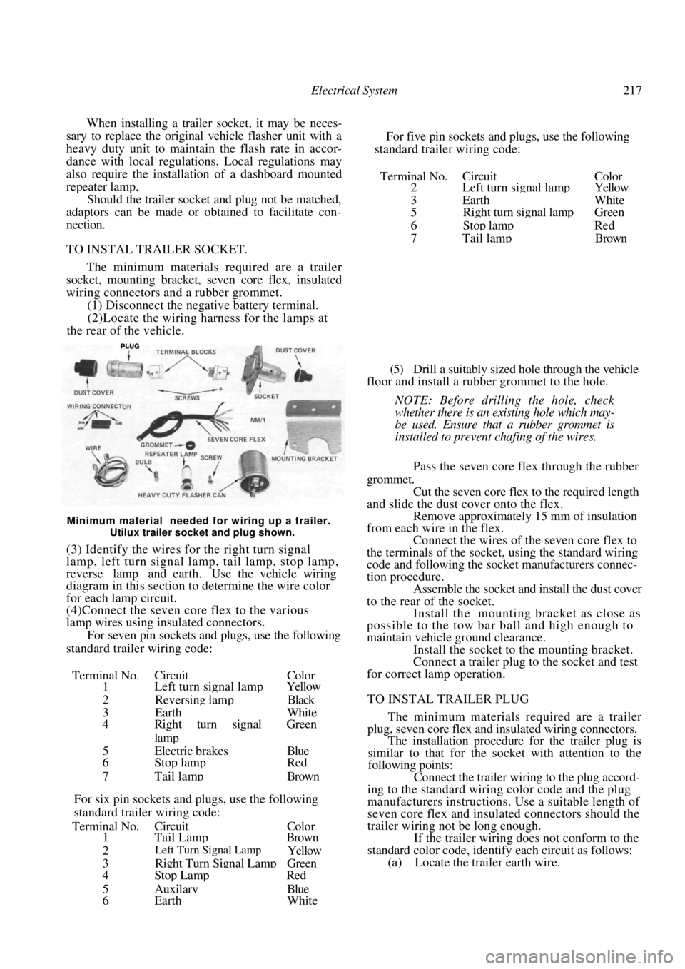
The minimum materials required are a trailer
socket, mounting bracket, seven core flex, insulated
wiring connectors and a rubber grommet.
(1) Disconnect the negative battery terminal.
(2)Locate the wiring harness for the lamps at
the rear of the vehicle.
For five pin sockets and plugs, use the following
standard trailer wiring code:
Terminal No.CircuitColor2 Left turn signal lampYellow
3Earth White
5 Ri
ght turn signal lampGreen
6Stop lamp Red
7 Tail lam
p Brown
Minimum material needed for wiring up a trailer.
Utilux trailer socket and plug shown.
(3) Identify the wires for the right turn signal
lamp, left turn signal lamp, tail lamp, stop lamp,
reverse lamp and earth. Use the vehicle wiring
diagram in this section to determine the wire color
for each lamp circuit.
(4)Connect the seven core flex to the various
lamp wires using insulated connectors.
For seven pin sockets and plugs, use the following
standard trailer wiring code:
Terminal No.CircuitColor1 Left turn signal lamp Yellow
2 Reversing lamp Black
3EarthWhite
4 Right turn signal Green
lamp
5Electric brakesBlue
6 Stop lampRed
7
Tail lampBrown
For six pin sockets and pl ugs, use the following
standard trailer wiring code:
Terminal No.CircuitColor1 Tail LampBrown
2 Left Turn Signal Lamp Yellow
3Right Turn Signal LampGreen
4 Stop LampRed
5AuxilaryBlue
6 Earth White
(5) Drill a suitably si
zed hole through the vehicle
floor and install a rubber grommet to the hole.
NOTE: Before drilling the hole, check
whether there is an existing hole which may-
be used. Ensure that a rubber grommet is
installed to prevent chafing of the wires.
Pass the seven core flex through the rubber
grommet. Cut the seven core flex to the required length
and slide the dust cover onto the flex. Remove approximately 15 mm of insulation
from each wire in the flex.
Connect the wires of the seven core flex to
the terminals of the socket, using the standard wiring
code and following the socket manufacturers connec-
tion procedure. Assemble the socket and install the dust cover
to the rear of the socket. Install the mounting bracket as close as
possible to the tow bar ball and high enough to
maintain vehicle ground clearance. Install the socket to the mounting bracket.
Connect a trailer plug to the socket and test
for correct lamp operation.
TO INSTAL TRAILER PLUG
The minimum materials required are a trailer
plug, seven core flex and insulated wiring connectors.
The installation procedure for the trailer plug is
similar to that for the socket with attention to the
following points:
Connect the trailer wiring to the plug accord-
ing to the standard wiring color code and the plug
manufacturers instructions. Use a suitable length of
seven core flex and insulated connectors should the
trailer wiring not be long enough.
If the trailer wiring does not conform to the
standard color code, identify each circuit as follows: (a) Locate the trailer earth wire.
PLUG