engine coolant NISSAN PULSAR 1987 Workshop Manual
[x] Cancel search | Manufacturer: NISSAN, Model Year: 1987, Model line: PULSAR, Model: NISSAN PULSAR 1987Pages: 238, PDF Size: 28.91 MB
Page 35 of 238
Roadside Trouble Shooting 35
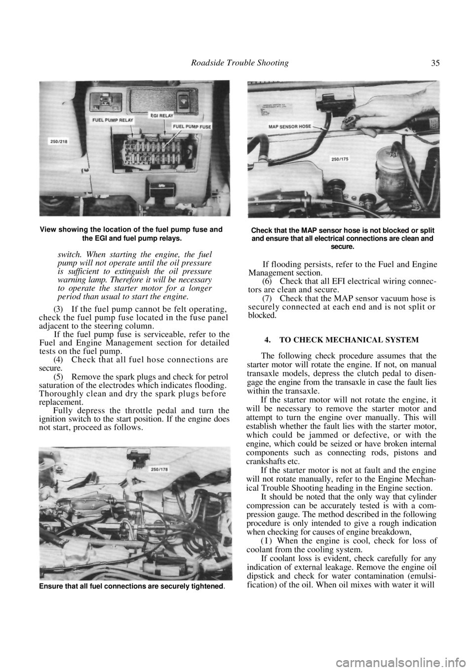
View showing the location of the fuel pump fuse and the EGI and fuel pump relays.
switch. When starting the engine, the fuel
pump will not operate until the oil pressure
is sufficient to extinguish the oil pressure
warning lamp. Therefore it will be necessary
to operate the starter motor for a longer
period than usual to start the engine.
(3) If the fuel pump cannot be felt operating,
check the fuel pump fuse located in the fuse panel
adjacent to the steering column.
If the fuel pump fuse is serviceable, refer to the
Fuel and Engine Management section for detailed
tests on the fuel pump.
(4) Check that all fuel hose connections are
secure.
(5) Remove the spark plugs and check for petrol
saturation of the electrodes which indicates flooding.
Thoroughly clean and dry the spark plugs before
replacement. Fully depress the throttle pedal and turn the
ignition switch to the start position. If the engine does
not start, proceed as follows.
Check that the MAP sensor hose is not blocked or split
and ensure that all electrical connections are clean and
secure.
If flooding persists, refer to the Fuel and Engine
Management section.
(6) Check that all EFI electrical wiring connec-
tors are clean and secure.
(7) Check that the MAP sensor vacuum hose is
securely connected at each end and is not split or
blocked.
4. TO CHECK MECHANICAL SYSTEM
The following check procedure assumes that the
starter motor will rotate the engine. If not, on manual
transaxle models, depress the clutch pedal to disen-
gage the engine from the tr ansaxle in case the fault lies
within the transaxle.
If the starter motor will not rotate the engine, it
will be necessary to remove the starter motor and
attempt to turn the engine over manually. This will
establish whether the fault lies with the starter motor,
which could be jammed or defective, or with the
engine, which could be seized or have broken internal
components such as connecting rods, pistons and
crankshafts etc.
If the starter motor is not at fault and the engine
will not rotate manually, refer to the Engine Mechan-
ical Trouble Shooting heading in the Engine section.
It should be noted that the only way that cylinder
compression can be accurately tested is with a com-
pression gauge. The method described in the following
procedure is only intended to give a rough indication
when checking for causes of engine breakdown,
(I) When the engine is cool, check for loss of
coolant from the cooling system.
If coolant loss is evident, check carefully for any
indication of external leakage. Remove the engine oil
dipstick and check for wate r contamination (emulsi-
fication) of the oil. When oil mixes with water it will
Ensure that all fuel connections are securely tightened.
Page 36 of 238
36 Roadside Trouble Shooting
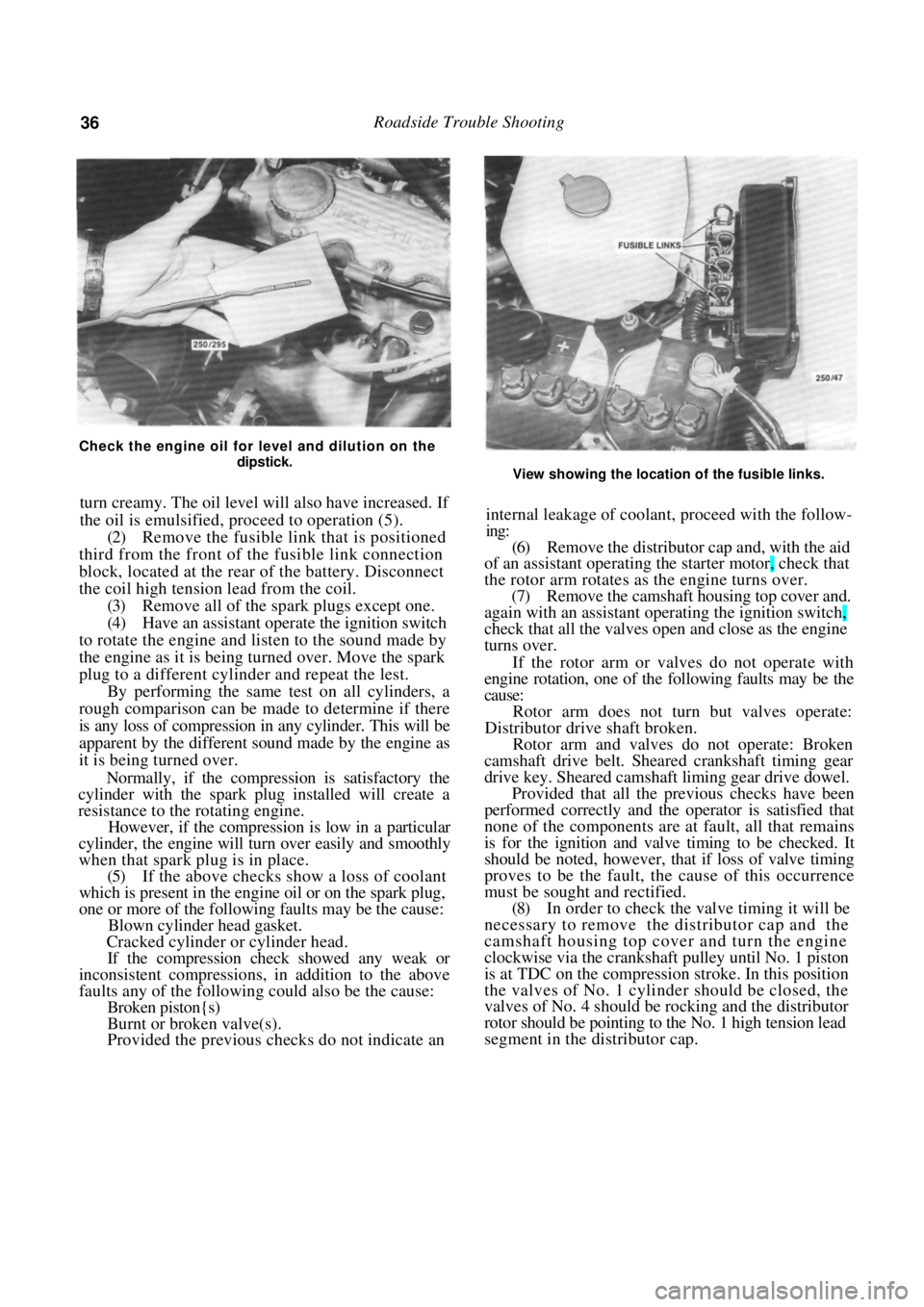
Check the engine oil for level and dilution on the dipstick.
turn creamy. The oil level will also have increased. If
the oil is emulsified, proceed to operation (5).
(2) Remove the fusible link that is positioned
third from the front of th e fusible link connection
block, located at the rear of the battery. Disconnect
the coil high tension lead from the coil. (3) Remove all of the spark plugs except one.
(4) Have an assistant operate the ignition switch
to rotate the engine and listen to the sound made by
the engine as it is being turned over. Move the spark
plug to a different cylinder and repeat the lest. By performing the same test on all cylinders, a
rough comparison can be made to determine if there
is any loss of compression in any cylinder. This will be
apparent by the different sound made by the engine as
it is being turned over.
Normally, if the compression is satisfactory the
cylinder with the spark plug installed will create a
resistance to the rotating engine.
However, if the compression is low in a particular
cylinder, the engine will tu rn over easily and smoothly
when that spark plug is in place.
(5) If the above checks show a loss of coolant
which is present in the engine oil or on the spark plug,
one or more of the following faults may be the cause:
Blown cylinder head gasket.
Cracked cylinder or cylinder head.
If the compression check showed any weak or
inconsistent compressions, in addition to the above
faults any of the following could also be the cause:
Broken piston{s)
Burnt or broken valve(s).
Provided the previous checks do not indicate an
View showing the location of the fusible links.
internal leakage of coolant, proceed with the follow-
ing:
(6) Remove the distributor cap and, with the aid
of an assistant operating th e starter motor, check that
the rotor arm rotates as the engine turns over. (7) Remove the camshaft hous ing top cover and.
again with an assistant operating the ignition switch,
check that all the valves open and close as the engine
turns over.
If the rotor arm or valves do not operate with
engine rotation, one of the following faults may be the
cause:
Rotor arm does not turn but valves operate:
Distributor drive shaft broken.
Rotor arm and valves do not operate: Broken
camshaft drive belt. Sheare d crankshaft timing gear
drive key. Sheared camshaft liming gear drive dowel.
Provided that all the previous checks have been
performed correctly and the operator is satisfied that
none of the components are at fault, all that remains
is for the ignition and valve timing to be checked. It
should be noted, however, that if loss of valve timing
proves to be the fault, th e cause of this occurrence
must be sought and rectified.
(8) In order to check the valve timing it will be
necessary to remove the distributor cap and the
camshaft housing top cover and turn the engine
clockwise via the crankshaft pulley until No. 1 piston
is at TDC on the compression stroke. In this position
the valves of No. 1 cylinder should be closed, the
valves of No. 4 should be rocking and the distributor
rotor should be pointing to the No. 1 high tension lead
segment in the distributor cap.
Page 42 of 238

42 Engine
The cylinder block is a cast iron alloy, deep skirt
design and the crankshaft is supported in the cylinder
block by five precision insert replaceable main bear-
ings. Crankshaft end float is controlled by the flanged
centre main bearing. Connecting rods are I section
forgings equipped with precision insert replaceable big
end bearings. The gudgeon pins are an interference fit
in the connecting rod and a floating fit in the piston.
The cast aluminum pistons are equipped with
two compression rings and one oil control ring.
The twin rotor, involute gear oil pump is mounted
directly to the front face of the cylinder block. The
inner rotor is internally driven by the crankshaft. The
oil pump pressure relief valve is not adjustable, and
consists of a plunger and spring mounted in the oil
pump body.
The pump draws oil through a screen in the sump
and delivers it, via a full flow replaceable oil filter, to
the oil gallery from where it is distributed to the
hydraulic tappets, camshaft and crankshaft bearings
and to the overhead rocker and valve mechanism.
3. ENGINE AND TRANSAXLE ASSEMBLY
Special Equipment Required:
To Remove and Instill — Suitable lifting tackle,
extra long chassis stands, suitable trolley
TO REMOVE
NOTE: Due to the high residual pressure
within the fuel system, it will be necessary to
depressurize the system before removing any
fuel supply components. Refer to the Fuel
and Engine Management section for the
correct procedure.
(1) Disconnect the negative battery terminal.
(2) Mark around the bonnet hinges with a soft
lead pencil Co facilitate correct installation. With the
aid of an assistant, remove the bonnet retaining bolts
and remove the bonnet from the vehicle.
(3) Drain the engine and transaxle lubricant.
(4) Open the coolant drain tap located on the
lower radiator pipe and drain the coolant. (5) Loosen the hose clips and disconnect the
heater hoses from the heater pipes at the bulkhead.
NOTE: Do not use excessive force to remove
the heater hoses from the heater pipes or the
heater core will become dislodged from the
heater unit. If necessary, cut the heater
hoses from the pipes using a sharp knife.
(6) Loosen the hose clamps and disconnect the
radiator hoses from the engine assembly. (7) Disconnect the positive lead from the bat-
tery. (8) On 1.8 liter models, disconnect the air inlet
duct.
(9) On 1.6 liter models, remove the air cleaner
assembly. Refer to the Fuel and Engine Management
section if necessary. (10) Disconnect the throttle cable from the throt-
tle body and from the camshaft housing top cover
bracket, if applicable. (11) Disconnect the fuel supply and return hoses.
Mark the hoses as an aid to installation. (12) Suitably mark and disconnect the charcoal
canister hoses. (13) Disconnect the injector wires from the injec-
tors. On 1.6 liter models, slide the wiring out from the
throttle body. (14) Disconnect the wiring fr om the throttle po-
sition sensor (TPS), idle air control (IAC) valve,
oxygen (O
2) sensor wire, coolant temperature sensor,
coolant sender and on 1.8 liter models, the manifold
air temperature (MAT) sensor. (15) Disconnect the wiring connector adjacent to
the top heater hose, the wiring from the alternator and
the two earth wires from underneath the cylinder head
bolts. (16) Lay the wiring loom over on the passenger
side of the engine compar tment, clear of the work
area.
(17) On manual transaxle models, loosen the
clutch cable adjusting nuts and remove the cable
through the slot in the lever. Remove the clutch cable
bracket from the transaxle after removing the retain-
ing bolts and place the cable to one side.
(18) Disconnect the wiring from the starter mo-
tor, speedometer sender and on manual transaxle
models, the reverse lamp switch wiring.
(19) If applicable, disconnect the power steering
lines from the pump and drain the fluid into a
container. Suitably plug the lines and the pump to
prevent the entry of dirt.
(20) On automatic transaxle models, disconnect
the selector cable and bracket from the transaxle
assembly.
Disconnect the transaxle oil cooler lines from the
transaxle. Plug the lines and fittings to prevent the
entry of dirt etc.
(21) Loosen the front wheel nuts, raise the front
of the vehicle and support it on extra long chassis
stands. Ensure that the vehicle is high enough to allow
removal of the engine from underneath. (22) Remove the front wheels and the engine
splash guards from the vehicle.
(23) On manual transaxle models, remove the
stay rod and control rod bolts and nuts and disconnect
the rods from the transaxle.
(24) Remove the lower control arm to steering
knuckle ball joint nuts and separate the ball joints
from the steering knuckle by holding a dolly or a
hammer against one side of the steering knuckle and
hitting the other side with a hammer. The taper on the
ball joint will release fr om the steering knuckle.
(25) Pull the steering knuckles outward swiftly to
Page 44 of 238
44 Engine
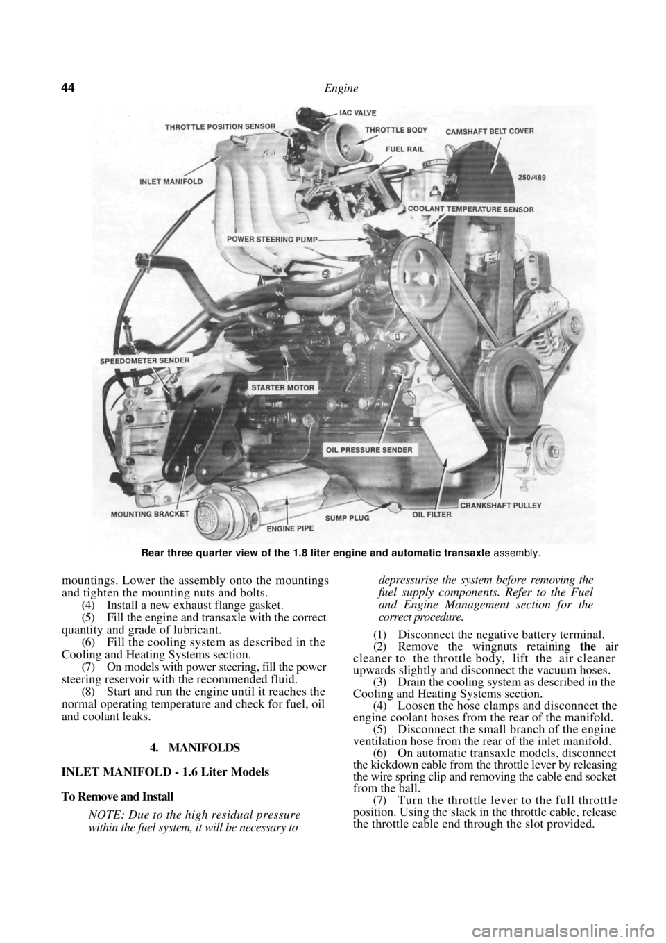
Rear three quarter view of the 1.8 liter engine and automatic transaxle assembly.
mountings. Lower the assembly onto the mountings
and tighten the mounting nuts and bolts.
(4) Install a new exhaust flange gasket.
(5) Fill the engine and transaxle with the correct
quantity and grade of lubricant. (6) Fill the cooling system as described in the
Cooling and Heating Systems section. (7) On models with power steering, fill the power
steering reservoir with the recommended fluid.
(8) Start and run the engine until it reaches the
normal operating temperatur e and check for fuel, oil
and coolant leaks.
4. MANIFOLDS
INLET MANIFOLD - 1.6 Liter Models
To Remove and Install
NOTE: Due to the high residual pressure
within the fuel system, it will be necessary to
depressurise the system before removing the
fuel supply components. Refer to the Fuel
and Engine Management section for the
correct procedure.
(1) Disconnect the negative battery terminal.
(2) Remove the wingnuts retaining the air
cleaner to the throttle body, lift the air cleaner
upwards slightly and disconnect the vacuum hoses. (3) Drain the cooling system as described in the
Cooling and Heating Systems section. (4) Loosen the hose clamps and disconnect the
engine coolant hoses from the rear of the manifold.
(5) Disconnect the small branch of the engine
ventilation hose from the rear of the inlet manifold. (6) On automatic transaxle models, disconnect
the kickdown cable from the throttle lever by releasing
the wire spring clip and re moving the cable end socket
from the ball.
(7) Turn the throttle lever to the full throttle
position. Using the slack in the throttle cable, release
the throttle cable end thr ough the slot provided.
Page 49 of 238
Engine 49
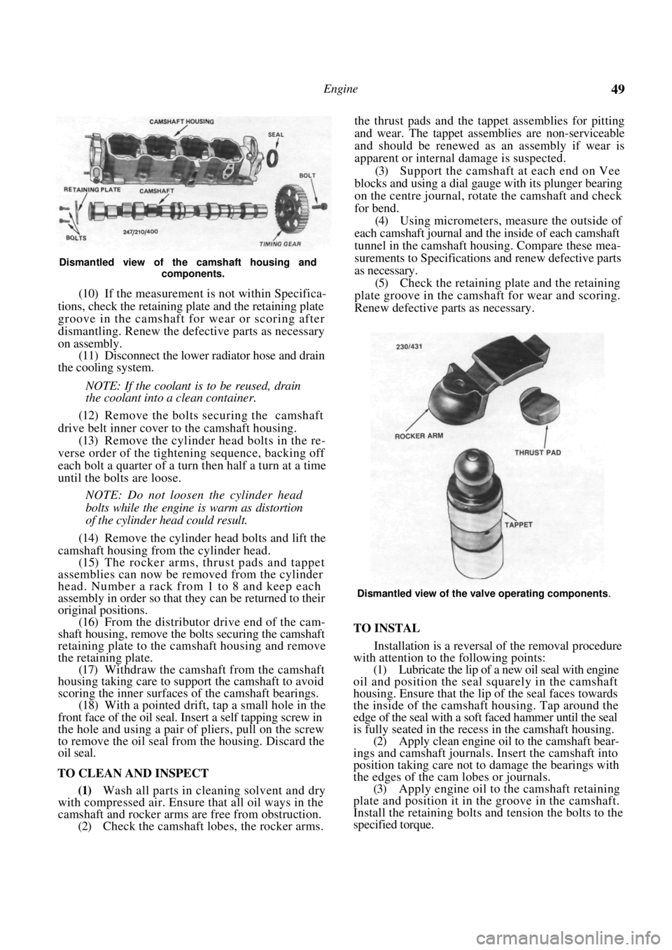
Dismantled view of the camshaft housing and components.
(10) If the measurement is not within Specifica-
tions, check the retaining plate and the retaining plate
groove in the camshaft for wear or scoring after
dismantling. Renew the defective parts as necessary
on assembly. (11) Disconnect the lower radiator hose and drain
the cooling system.
NOTE: If the coolant is to be reused, drain
the coolant into a clean container.
(12) Remove the bolts securing the camshaft
drive belt inner cover to the camshaft housing. (13) Remove the cylinder head bolts in the re-
verse order of the tighten ing sequence, backing off
each bolt a quarter of a turn then half a turn at a time
until the bolts are loose.
NOTE: Do not loosen the cylinder head
bolts while the engine is warm as distortion
of the cylinder head could result.
(14) Remove the cylinder head bolts and lift the
camshaft housing from the cylinder head. (15) The rocker arms, thrust pads and tappet
assemblies can now be removed from the cylinder
head. Number a rack from 1 to 8 and keep each
assembly in order so that they can be returned to their
original positions.
(16) From the distributor drive end of the cam-
shaft housing, remove the bolts securing the camshaft
retaining plate to the camshaft housing and remove
the retaining plate. (17) Withdraw the camshaft from the camshaft
housing taking care to supp ort the camshaft to avoid
scoring the inner surfaces of the camshaft bearings.
(18) With a pointed drift, tap a small hole in the
front face of the oil seal. Insert a self tapping screw in
the hole and using a pair of pliers, pull on the screw
to remove the oil seal from the housing. Discard the
oil seal.
TO CLEAN AND INSPECT
(1) Wash all parts in cleaning solvent and dry
with compressed air. Ensure that all oil ways in the
camshaft and rocker arms are free from obstruction.
(2) Check the camshaft lobes, the rocker arms. the thrust pads and the ta
ppet assemblies for pitting
and wear. The tappet assemblies are non-serviceable
and should be renewed as an assembly if wear is
apparent or internal damage is suspected.
(3) Support the camshaft at each end on Vee
blocks and using a dial gauge with its plunger bearing
on the centre journal, rotate the camshaft and check
for bend. (4) Using micrometers, measure the outside of
each camshaft journal and the inside of each camshaft
tunnel in the camshaft housing. Compare these mea-
surements to Specifications and renew defective parts
as necessary. (5) Check the retaining plate and the retaining
plate groove in the camshaft for wear and scoring.
Renew defective parts as necessary.
Dismantled view of the valve operating components.
TO INSTAL
Installation is a reversal of the removal procedure
with attention to the following points:
(1) Lubricate the lip of a new oil seal with engine
oil and position the seal squarely in the camshaft
housing. Ensure that the li p of the seal faces towards
the inside of the camshaft housing. Tap around the
edge of the seal with a soft faced hammer until the seal
is fully seated in the recess in the camshaft housing. (2) Apply clean engine oil to the camshaft bear-
ings and camshaft journals. Insert the camshaft into
position taking care not to damage the bearings with
the edges of the cam lobes or journals. (3) Apply engine oil to the camshaft retaining
plate and position it in the groove in the camshaft.
Install the retaining bolts and tension the bolts to the
specified torque.
Page 50 of 238

50 Engine
(4) Ensure that the tappet assemblies are full of
clean engine oil and insert the tappets in their
respective bores in the cylinde r head. Install the thrust
pads to the top of each valve assembly ensuring that
they are returned to their original location.
(5) Coat the contact surfaces of the rocker arms
with molybdenum disulphide grease and install the
rocker arms to their origin al locations on the cylinder
head. (6) Clean the mating surfaces of the camshaft
housing and cylinder head. Apply a bead of Loctite
515 to the cylinder head and camshaft housing mating
surfaces. Take care that no sea lant is forced into the
oil passages and install the camshaft housing to the
cylinder head.
(7) Install new cylinder head bolts and lubricate
the bolts and washers with oil.
(8) Apply an initial torque to the cylinder head
bolts of 25 Nm in the corr ect sequence as shown in
the illustration under the Cylinder Head heading.
Further tighten the head bolts in the correct sequence,
in three separate 60 degree stages. Refer to Specifica-
tions. (9) Install the bolts securing the camshaft
drive
belt inner cover to the camshaft housing. (10) Install the camshaft timing gear to the cam-
shaft ensuring that it is correctly located. Tighten the
camshaft timing gear retain ing boll to the specified
torque. (11) Install and adjust the camshaft drive belt as
described under the previous heading. (12) Install the distributor. Refer to the Fuel and
Engine Management section.
(13) Connect the lower radiat or hose and fill the
cooling system with the required coolant. Refer to the
Cooling and Heating Systems section if necessary. (14) Start and run the engine until normal oper-
ating temperature is attained and tighten the cylinder
head bolts another 30-50 degrees in the correct
sequence, ensuring that the tension does not exceed
135 Nm.
TO RENEW CAMSHAFT OIL SEAL,
CAMSHAFT INSTALLED
(1) Remove the camshaft drive belt from the
camshaft timing gear as described under the previous
heading.
(2) Remove the camshaft housing top cover
retaining bolts, remove the cover and discard the
gasket.
(3) Use an open end spanner to hold the cam-
shaft between the inlet and exhaust lobes of number
four cylinder and remove the camshaft timing gear
retaining bolt and the camshaft timing gear. (4) With a pointed drift, tap a small hole in the
front face of the oil seal. Insert a self tapping screw in
the hole and using a pair of pliers, pull on the screw
to remove the oil seal from the housing.
(5) Clean the seal recess and the camshaft sea!
running surface. (6) Lubricate the lip of a new oil seal with engine
oil and slide the seal over the camshaft. Ensure that
the lip of the seal faces to wards the inside of the
camshaft housing. Tap evenly around the edges of the
seal until it is fully seated in the camshaft housing.
(7) Install the camshaft timing gear to the cam-
shaft, ensuring that it is co rrectly located. Tighten the
camshaft timing gear retain ing bolt to the specified
torque. Do not allow the camshaft to rotate while
tightening the bolt. (8) Install and adjust the drive belt as described
under the previous heading. Ensure that the timing
marks are aligned. (9) Install the camshaft hou sing top cover using a
new gasket. Tighten the retaining bolts to the specified
torque.
7. CYLINDER HEAD
Special Equipment Required:
To Dismantle and Assemble — Valve spring com-
pressor
To Inspect — Dial gauge and straight edge
To Install — Drive belt adjusting tool
TO REMOVE AND INSTAL
NOTE: Due to the high residua! pressure
within the fuel system, it will be necessary to
depressurize the system before removing any
fuel supply components. Refer to the Fuel
and Engine Management section for the
correct procedure.
Allow the engine to cool prior to the
removal of the cylinder head to prevent
possible distortion of the cylinder head.
(1) Disconnect the negative battery terminal and
remove the nuts securing the earth wires to the
cylinder head bolts.
(2) Remove the camshaft drive belt as previ-
ously described.
(3) Disconnect the lower radiator hose and drain
the cooling system. Refer to the Cooling and Heating
Systems section if necessary. (4) Remove the alternator adjusting bracket
mounting bolt and insulating washers from the inlet
manifold. Loosen the adjusting bolt at the alternator
and slide the bracket away from the cylinder head. (5) Disconnect the upper radiator hose, coolant
by-pass hose and the heater hose from the thermostat
housing and on 1.6 liter m odels, the coolant hoses
from the inlet manifold. (6) Disconnect the electrica l connectors from the
throttle body, fuel injectors, coil, distributor and on
1.8 liter models, the MAT sensor. (7) Disconnect the oxygen sensor wiring connec-
tor and remove the wiring connectors from the
Page 51 of 238
Engine 51
coolant temperature sensor and temperature sender
switch located in the thermostat housing.
(8) Remove the bolt securing the wiring clamp
to the rear of the manifold and maneuver the wiring
away from the cylinder head and the inlet manifold.
(9) Disconnect the throttle cable and on auto-
matic transaxle models, the kickdown cable from the
throttle body linkage. (10) Remove the bolls securing the throttle cable
bracket to the inlet manifold and place the bracket
and cable(s) to one side.
(11) Mark the fuel supply and return hoses to
ensure correct installation and disconnect the hoses
from the fuel rail or throttle body. Plug the hoses to
prevent the loss of fuel or the entry of dirt. (12) Mark the vacuum hoses connected to the
inlet manifold and throttle body to ensure correct
installation and disconnect the hoses. (13) Remove the nuts securing the engine pipe to
the exhaust manifold and separate the pipe from the
manifold. (14) Remove the oxygen sensor from the exhaust
manifold. Refer to the Fuel and Engine Management
section if necessary. (15) Remove the distributor and coil as described
in the Fuel and Engine Management section. (16) Disconnect the engine breather hoses from
the camshaft housing and cams haft housing top cover.
(17) Remove the bolts retaining the top cover to
the camshaft housing and remove the top cover. (18) Using an open end spanner, hold the cam-
shaft between the inlet and exhaust lobes of number
four cylinder and remove the camshaft timing gear
retaining bolt and the camshaft timing gear.
(19) Remove the bolts securing the camshaft
drive belt inner cover to the camshaft housing. (20) Loosen the cylinder head bolts in the reverse
order of the tightening sequence, backing off each bolt
a quarter turn then half a turn at a time until the bolts
are loose.
NOTE: Do not loosen the head bolts while
the engine is warm as distortion of the
cylinder head could result.
(21) Remove the cylinder head bolts and lift the
camshaft housing from the cylinder head. (22) Remove the cylinder head and gasket from
the cylinder block. Installation is a reversal of the removal procedure
with attention to the following points:
(1) Thoroughly clean the gasket surfaces of the
cylinder head, cylinder block and camshaft housing
and check all mating surfaces with a straight edge.
Ensure that all the oilways are clean and free of any
foreign material and lightly oil all operating parts with
engine oil.
(2) Install new gaskets throughout during
assem-
bly.
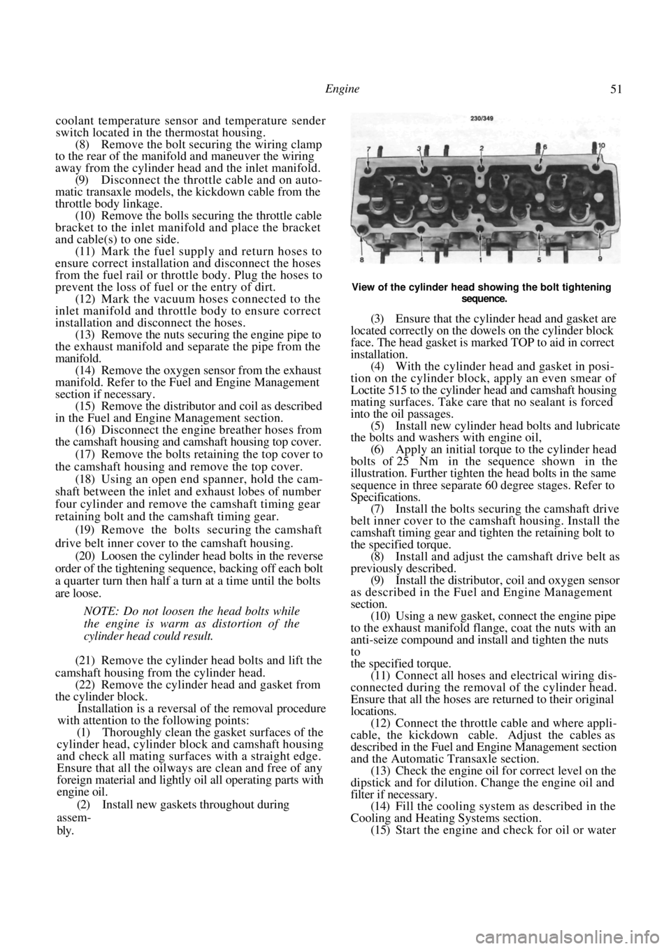
View of the cylinder head showing the bolt tightening
sequence.
(3) Ensure that the cylinde r head and gasket are
located correctly on the dowels on the cylinder block
face. The head gasket is marked TOP to aid in correct
installation. (4) With the cylinder head and gasket in posi-
tion on the cylinder block, apply an even smear of
Loctite 515 to the cylinder head and camshaft housing
mating surfaces. Take care that no sealant is forced
into the oil passages. (5) Install new cylinder head bolts and lubricate
the bolts and washers with engine oil,
(6) Apply an initial torque to the cylinder head
bolts of 25 Nm in the sequence shown in the
illustration. Further tighten the head bolts in the same
sequence in three separate 60 degree stages. Refer to
Specifications. (7) Install the bolts secur ing the camshaft drive
belt inner cover to the camshaft housing. Install the
camshaft timing gear and tighten the retaining bolt to
the specified torque. (8) Install and adjust the camshaft drive belt as
previously described. (9) Install the distributor, coil and oxygen sensor
as described in the Fuel and Engine Management
section.
(10) Using a new gasket, connect the engine pipe
to the exhaust manifold flange, coat the nuts with an
anti-seize compound and install and tighten the nuts
to
the specified torque. (11) Connect all hoses and electrical wiring dis-
connected during the removal of the cylinder head.
Ensure that all the hoses are returned to their original
locations. (12) Connect the throttle cable and where appli-
cable, the kickdown cable. Adjust the cables as
described in the Fuel and Engine Management section
and the Automatic Transaxle section. (13) Check the engine oil fo r correct level on the
dipstick and for dilution. Change the engine oil and
filter if necessary. (14) Fill the cooling system as described in the
Cooling and Heating Systems section. (15) Start the engine and check for oil or water
Page 56 of 238
56 Engine
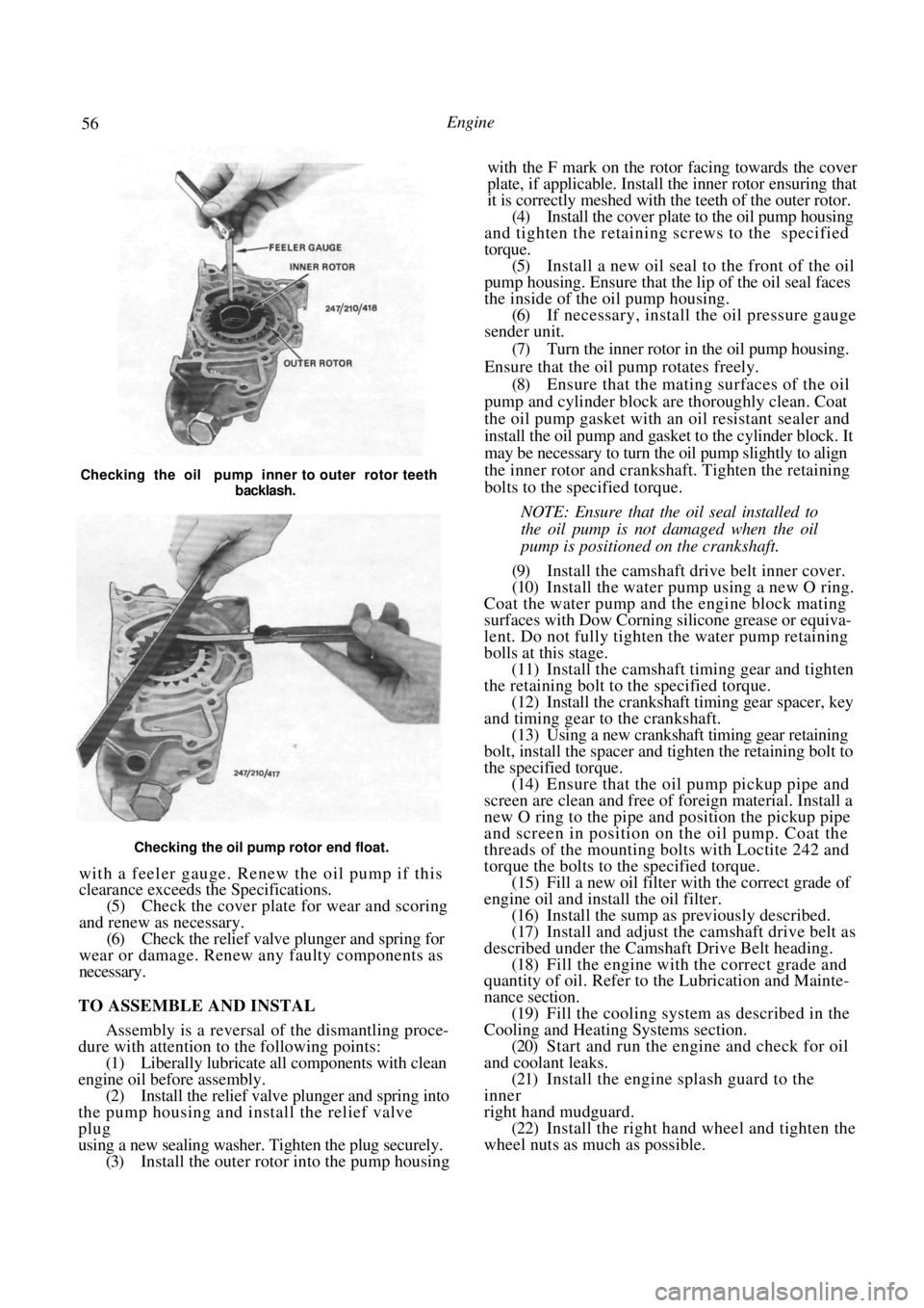
Checking the oil pump rotor end float.
with a feeler gauge. Renew the oil pump if this
clearance exceeds the Specifications.
(5) Check the cover plate for wear and scoring
and renew as necessary. (6) Check the relief valve plunger and spring for
wear or damage. Renew any faulty components as
necessary.
TO ASSEMBLE AND INSTAL
Assembly is a reversal of the dismantling proce-
dure with attention to the following points:
(1) Liberally lubricate all components with clean
engine oil before assembly. (2) Install the relief valve plunger and spring into
the pump housing and install the relief valve
plug
using a new sealing washer. Tighten the plug securely. (3) Install the outer rotor into the pump housing with the F mark on the rotor facing towards the cover
plate, if applicable. Install the inner rotor ensuring that
it is correctly meshed with the teeth of the outer rotor.
(4)
Install the cover plate to the oil pump housing
and tighten the retaining screws to the specified
torque. (5) Install a new oil seal to the front of the oil
pump housing. Ensure that the lip of the oil seal faces
the inside of the oil pump housing. (6) If necessary, install the oil pressure gauge
sender unit.
(7) Turn the inner rotor in the oil pump housing.
Ensure that the oil pump rotates freely. (8) Ensure that the mating surfaces of the oil
pump and cylinder block are thoroughly clean. Coat
the oil pump gasket with an oil resistant sealer and
install the oil pump and gasket to the cylinder block. It
may be necessary to turn the oil pump slightly to align
the inner rotor and crankshaft. Tighten the retaining
bolts to the specified torque.
NOTE: Ensure that the oil seal installed to
the oil pump is not damaged when the oil
pump is positioned on the crankshaft.
(9) Install the camshaft drive belt inner cover.
(10) Install the water pump using a new O ring.
Coat the water pump and the engine block mating
surfaces with Dow Corning silicone grease or equiva-
lent. Do not fully tighten the water pump retaining
bolls at this stage. (11) Install the camshaft timing gear and tighten
the retaining bolt to the specified torque.
(12) Install the crankshaft timing gear spacer, key
and timing gear to the crankshaft. (13) Using a new crankshaft timing gear retaining
bolt, install the spacer and tighten the retaining bolt to
the specified torque. (14) Ensure that the oil pump pickup pipe and
screen are clean and free of foreign material. Install a
new O ring to the pipe and position the pickup pipe
and screen in position on the oil pump. Coat the
threads of the mounting bolts with Loctite 242 and
torque the bolts to the specified torque. (15) Fill a new oil filter with the correct grade of
engine oil and install the oil filter. (16) Install the sump as previously described.
(17) Install and adjust the camshaft drive belt as
described under the Camshaft Drive Belt heading. (18) Fill the engine with the correct grade and
quantity of oil. Refer to the Lubrication and Mainte-
nance section.
(19) Fill the cooling system as described in the
Cooling and Heating Systems section. (20) Start and run the engine and check for oil
and coolant leaks. (21) Install the engine splash guard to the
inner
right hand mudguard. (22) Install the right hand wheel and tighten the
wheel nuts as much as possible.
Checking the oil pump inner to outer rotor teeth
backlash.
Page 68 of 238
68
COOLING AND HEATING SYSTEMS
SPECIFICATIONS
Coolant capacity ........................................ 6.0 liters
Thermostat:
Opening temperature........................... 91 deg
C
Fully open temperature .................... 103 deg
C
Cooling fan:
Fan cut in temperat ure ....................... 100 deg C
Fan cut out temperature ...................... 95 deg C
Radiator cap opening
pressure ................................................... 78 -98 kPa
TORQUE WRENCH SETTINGS
Water pump retaining bolts .............................25 Nm
Thermostat housing bolts .................................15 Nm
Sender unit .......................................................10 Nm
1. COOLING SYSTEM TROUBLE SHOOTING
COOLANT LEAKAGE - EXTERNAL
(1) Loose hose clips or faulty hoses: Tighten the
hose clips or renew the faulty water hoses.
(2) Leaking radiator core or tanks: Repair or
renew the radiator. (3) Leaking heater core or hoses: Repair or renew the heater core. Check the hose clips and hoses
and renew if necessary.
(4)
Leaks at the thermostat cover and/or water
pump O rings. Renew the O rings. (5) Worn or damaged water pump seal assembly:
Renew the water pump. (6) Worn or damaged water pump bearing as-
sembly: Renew the water pump.
(7) Loose or rusted welch plugs; Renew the
welch plugs. (8) Faulty cylinder head gasket or loose cylinder
head bolts: Renew the cylinder head gasket and
correctly tighten the cylinder head bolts. (9) External crack in the cy linder head or cylin-
der block: Repair or renew the faulty components.
NOTE: Check the system for external leak-
age by running the engine to operating
temperature over a dry floor and checking
for the leak source.
Check the vehicle interior below the
heater core for moisture. If a rusted welch
plug is found, it is a good practice to renew
all the welch plugs.
COOLANT LEAKAGE - INTERNAL
( 1 ) Cylinder head gasket leak due to warped
cylinder head or cylinder block gasket faces: Reface
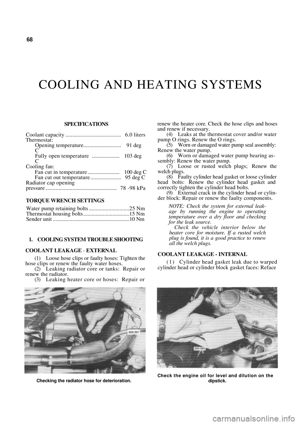
Checking the radiator hose for deterioration.
Check the engine oil for level and dilution on the
dipstick.
Page 69 of 238
Cooling and Heating Systems 69
the cylinder head or cylinder block and renew the
cylinder head gasket.
(2) Crack in the cylinder head or cylinder block:
Repair or renew as necessary.
NOTE; Check the engine for internal leak-
age by withdrawing the dipstick and inspect-
ing for emulsified oil. Run the engine and
check for excessive steam at the exhaust
pipe which would indi cate coolant leakage
into the combustion chamber.
COOLANT LOSS BY OVERFLOW
(1) Overfull system: Drain the excess coolant
from the system.
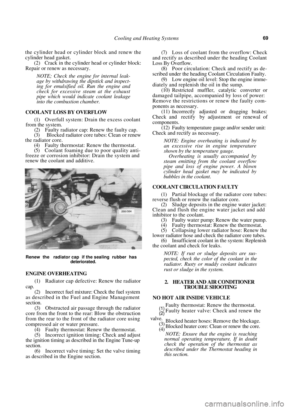
(2) Faulty radiator cap: Renew the faulty cap.
(3) Blocked radiator core tubes: Clean or renew
the radiator core.
(4) Faulty thermostat: Renew the thermostat.
(5) Coolant foaming due to poor quality anti-
freeze or corrosion inhibitor: Drain the system and
renew the coolant and additive.
Renew the radiator cap if the sealing rubber has
deteriorated.
ENGINE OVERHEATING
(1) Radiator cap defective: Renew the radiator
cap.
(2) Incorrect fuel mixture: Check the fuel system
as described in the Fuel and Engine Management
section. (3) Obstructed air passage through the radiator
core from the front to the rear: Blow the obstruction
from the rear to the front of the radiator core using
compressed air or water pressure. (4) Faulty thermostat: Renew the thermostat.
(5) Incorrect ignition timing: Check and adjust
the ignition timing as described in the Engine Tune-up
section. (6) Incorrect valve timing: Set the valve timing
as described in th e Engine section.
(7) Loss of coolant from the overflow: Check
and rectify as described under the heading Coolant
Loss By Overflow.
(8) Poor circulation: Check and rectify as de-
scribed under the heading Coolant Circulation Faulty.
(9) Low engine oil level: Stop the engine imme-
diately and replenish the oil in the sump. (10) Restricted muffler, catalytic converter or
damaged tailpipe, accompanied by loss of power:
Remove the restrictions or renew the faulty com-
ponents as necessary.
(11) Incorrectly adjusted or dragging brakes:
Check and rectify by adjustment or renewal of
components. (12) Faulty temperature gauge and/or sender unit:
Check and rectify as necessary.
NOTE: Engine overheating is indicated by
an excessive rise in engine temperature
shown by the temperature gauge.
Overheating is usually accompanied by
steam emitting from the coolant overflow
pipe and loss of engine power. A blown
cylinder head gasket may be indicated by
bubbles in the coolant.
COOLANT CIRCULATION FAULTY
(1) Partial blockage of the radiator core tubes:
reverse flush or renew the radiator core.
(2) Sludge deposits in the engine water jacket:
Clean and flush the engine water jacket and add
inhibitor to the coolant. (3) Faulty water pump: Renew the water pump.
(4) Faulty thermostat: Renew the thermostat.
(5) Collapsing lower radiator hose: Renew the
lower radiator hose and check the radiator core tubes. (6) Insufficient coolant in the system: Replenish
the coolant and check for leaks.
NOTE: If rust or sludge deposits are sus-
pected, check the color of the coolant in the
radiator. Rusty or muddy coolant indicates
rust or sludge in the system.
2. HEATER AND AIR CONDITIONER TROUBLE SHOOTING
NO HOT AIR INSIDE VEHICLE
Faulty thermostat: Renew the thermostat.
Faulty heater valve: Check and renew the
Blocked heater hoses: Remove the blockage.
Blocked heater core: Clean or renew the core.
NOTE: Ensure that the engine is reaching
normal operating temperature. If in doubt
check the operation of the thermostat as
described under the Thermostat heading in
this section.
(1)
(2)
valve.
(3)
(4)