cylinder head NISSAN PULSAR 1987 Workshop Manual
[x] Cancel search | Manufacturer: NISSAN, Model Year: 1987, Model line: PULSAR, Model: NISSAN PULSAR 1987Pages: 238, PDF Size: 28.91 MB
Page 3 of 238
CONTENTS
INTRODUCTION........................................ 5
VEHICLE IDENTIFICATION AND
GENERAL SPECIFICATIONS................. 7
GENERAL INFORMATION...................... 8
Tools and equipment ............................................. 8 Safety .................................................................... 10
General repair procedures..................................... 11
LUBRICATION AND MAINTENANCE... 14
Specifications......................................................... 14
How to grease and oil change .............................. 14
Service schedule ................................................... 17
WHEELS AND TYRES............................. 21
Specifications......................................................... 21
How to change a road wheel ................................ 21
Tire wear troubl e shooting ..................................... 22
Care and main tenance ......................................... 23
ENGINE TUNE-UP.................................... 25
Tune-up specifications ........................................... 25
Tune-up operat ions............................................... 25
ROADSIDE TROUBLE SHOOTING....... 32
Trouble shoot ing.................................................... 32
To check ignition and el ectrical system ................ 33
To check fuel system ............................................ 34
To check mechani cal system ................................ 35
ENGINE....................................................... 37
Specifications ........................................................ 37
Engine mechanical tr ouble shooting ...................... 39
Description ............................................................ 41
Engine and transaxle assembly ........................... 42
Manifolds ............................................................... 44 Camshaft, rocker arms and tappets..................... 48
Cylinder head........................................................ 50
Engine sump and oil pum p pickup pipe................ 54
Oil pump ............................................................... 55
Pistons, connecting rods and cylinder bores ........ 57
Crankshaft and bearings ...................................... 60
Flywheel /drive plate............................................... 63
Engine mountings.................................................. 64
Exhaust system .................................................... 66
COOLING AND HEATING SYSTEMS.... 68
Specifications ........................................................ 68 Cooling system trouble shooting ........................... 68
Heater and air conditioner trouble shooting ......... 69 Description ............................................................ 70
Radiator ................................................................ 70
Cooling fan ............................................................ 73
Thermost at............................................................ 75
Thermostat housing .............................................. 76
Water pump .......................................................... 76
Welch plugs .......................................................... 76
Heater unit, water valv e and controls ................... 77
Blower fan ............................................................. 80
Air condition ing ..................................................... 80
FUEL AND ENGINE MANAGEMENT ... 82
Specifications ........................................................ 82 Fuel and engine management trouble shooting ... 82
Description ............................................................ 84
Service precautions and procedures
..................... 86
System diagnosis and adjustments ...................... 89
Fuel supply components ....................................... 92
Air flow components .............................................. 98
Electronic components .......................................... 104
EMISSION CONTROL............................. 117
Introduction ........................................................... 117
Crankcase ventilati on system............................... 117
Evaporate control system..................................... 117
Air preheat system — 1.6 liter engines ................ 119
Exhaust control system ........................................ 120
CLUTCH...................................................... 121
Specifications........................................................ 121
Clutch trouble shooting......................................... 121
Description ............................................................ 122
Clutch unit and release mechanism..................... 123
Clutch pedal ......................................................... 124
Clutch c able.......................................................... 124
Clutch adjustments ............................................... 125
MANUAL TRANSAXLE AND
DRIVE SHAFTS......................................... 126
Specifications ........................................................ 126
Manual transaxle and drive shaft trouble shooting 126
Description............................................................ 128
Transaxle assembly.............................................. 129
Differential and final drive assembly ..................... 135
Gear lever assembly ............................................ 136
Drive shafts .......................................................... 137
AUTOMATIC TRANSAXLE....................... 140
Specifications........................................................ 140
Automatic transaxle trouble shooting.................... 140
Description............................................................ 141
Transaxle fluid ...................................................... 141
Brake band........................................................... 142
Kickdown cable .................................................... 142
Transaxle select or linkage ................................... 142
Neutral safety switch ............................................ 142
Transaxle assembly .............................................. 143
STEERING................................................. 145
PART 1. STEERING TROUBLE SHOOTING....145
Faults, causes and remedies................................ 145
PART 2. MANUA L STEERING......................... 147
Specifications ........................................................ 147
Description............................................................ 147
Steering wheel ...................................................... 147
Steering column.................................................... 148
Steering gear assembly ....................................... 149
PART 3. POWE R STEERING .......................... 152
Specifications........................................................ 152
Description............................................................ 152
In car adjustments, checks and minor repairs ..... 152
Steering wheel ...................................................... 153
Steering column.................................................... 153 Power steering pump ........................................... 153
Power steering gear assembly............................. 154
Page 12 of 238
12 General Information
Damaged threads can be repaired using a die nut
on studs and bolts, and a tap on nuts and threaded
holes in castings. If the threads of a threaded hole are
damaged beyond repair, it will be necessary to drill
and tap the hole to a larger size. Alternatively, a
Helicoil insert can be used to Testore the hole to the
original thread size.
STUDS
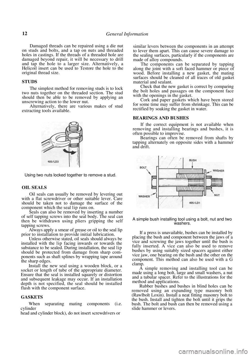
The simplest method for removing studs is to lock
two nuts together on the threaded section. The stud
should then be able to be removed by applying an
unscrewing action to the lower nut.
Alternatively, there are various makes of stud
extracting tools available.
Using two nuts locked together to remove a stud.
OIL SEALS
Oil seals can usually be removed by levering out
with a flat screwdriver or other suitable lever. Care
should be taken not to damage the surface of the
component which the seal lip runs on.
Seals can also be removed by inserting a number
of self tapping screws into the seal body. The seal can
then be withdrawn using pliers gripping the self
tapping screws.
Always apply a smear of grease or oil to the seal lip
prior to installation to provide initial lubrication.
Unless otherwise stated, oil seals should always be
installed with the lip facing inwards or towards the
substance to be sealed. Duri ng installation, the seal l i p
should be protected from damage from sharp com-
ponents such as shaft splines by wrapping tape around
the sharp edges.
Install the new seal using a wooden block, or a
socket or length of tube of the appropriate diameter.
Ensure that the seal is installed squarely or distortion
and subsequent leakage may occur. If an installation
depth is not specified, th e seal should be installed
flush with the component surface.
GASKETS
When separating mating components (i.e.
cylinder
head and cylinder block), do not insert screwdrivers or
similar levers between the components in an attempt
to lever them apart. This can cause severe damage to
the sealing surfaces, particularly if the components are
made of alloy compounds.
The components can be separated by tapping
along the joint with a soft faced hammer or piece of
wood. Before installing a new gasket, the mating
surfaces should be cleaned of all traces of old gasket
material and sealant.
Check that the new gasket is correct by comparing
the bolt holes and passages on the component face
with the openings in the gasket.
Cork and paper gaskets which have been stored
for some time may suffer from shrinkage. This can be
rectified by soaking the gasket in water.
BEARINGS AND BUSHES
If the correct equipment is not available when
removing and installing bearings and bushes, it is
often possible to improvise.
Bearings can often be removed from shafts by
tapping alternately on opposite sides with a hammer
and drift.
A simple bush installing tool using a bolt, nut and two
washers.
If a press is unavailable, bushes can be installed by
placing the bush and component between the jaws of a
vice and screwing the jaws together until the bush is
fully inserted. A vice can also be used to remove
bushes by using suitably sized spacers against either
vice jaw, one bearing on the bush and the other on the
component. This method can also be used with a G
clamp.
A simple removing and installing tool can be
made using a long bolt, large and small washers, a nut
and a tubular spacer. Refer to the illustrations for the
method and applications.
Rubber bushes and bushes in blind holes can be
removed using an expanding type masonry bolt
(Rawlbolt Loxin). Install a neat fitting masonry bolt to
the bush. Install and tighten the bolt until it grips the
bush. The bolt and bush can then be removed using a
slide hammer or levers.
Page 28 of 238
Engine Tune-up
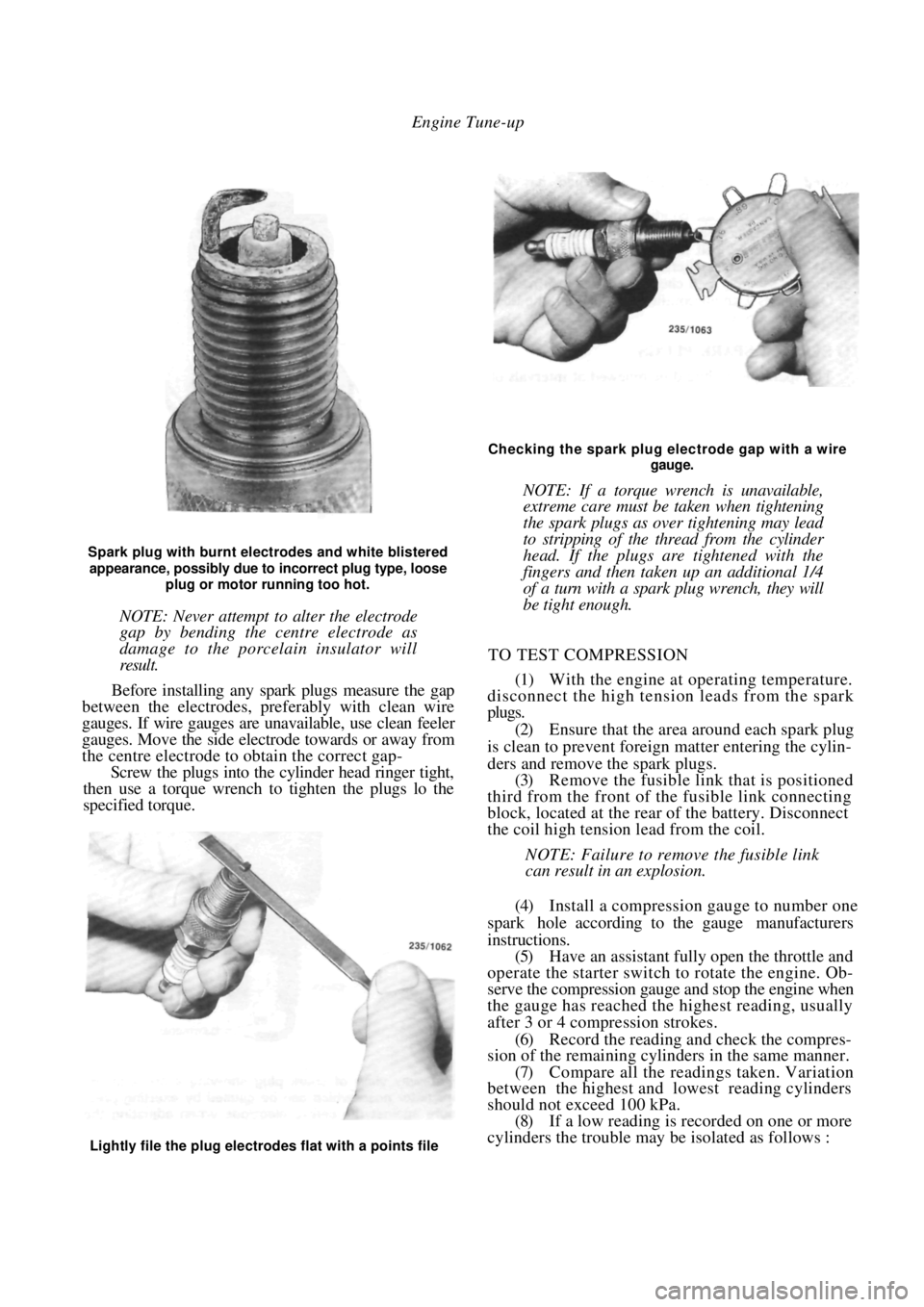
Spark plug with burnt electrodes and white blistered
appearance, possibly due to incorrect plug type, loose
plug or motor running too hot.
NOTE: Never attempt to alter the electrode
gap by bending the centre electrode as
damage to the porcelain insulator will
result.
Before installing any spark plugs measure the gap
between the electrodes, pref erably with clean wire
gauges. If wire gauges are una vailable, use clean feeler
gauges. Move the side electrode towards or away from
the centre electrode to obtain the correct gap-
Screw the plugs into the cylinder head ringer tight,
then use a torque wrench to tighten the plugs lo the
specified torque.
Checking the spark plug electrode gap with a wire
gauge.
NOTE: If a torque wrench is unavailable,
extreme care must be taken when tightening
the spark plugs as over tightening may lead
to stripping of the thread from the cylinder
head. If the plugs are tightened with the
fingers and then taken up an additional 1/4
of a turn with a spark plug wrench, they will
be tight enough.
TO TEST COMPRESSION
(1) With the engine at operating temperature.
disconnect the high tension leads from the spark
plugs.
(2) Ensure that the area around each spark plug
is clean to prevent foreign matter entering the cylin-
ders and remove the spark plugs. (3) Remove the fusible link that is positioned
third from the front of th e fusible link connecting
block, located at the rear of the battery. Disconnect
the coil high tension lead from the coil.
NOTE: Failure to remove the fusible link
can result in an explosion.
(4) Install a compression gauge to number one
spark hole according to the gauge manufacturers
instructions. (5) Have an assistant fully open the throttle and
operate the starter switch to rotate the engine. Ob-
serve the compression gauge and stop the engine when
the gauge has reached the highest reading, usually
after 3 or 4 compression strokes.
(6) Record the reading a nd check the compres-
sion of the remaining cylinders in the same manner.
(7) Compare all the readings taken. Variation
between the highest and lowest reading cylinders
should not exceed 100 kPa. (8) If a low reading is recorded on one or more
cylinders the trouble may be isolated as follows :
Lightly file the plug electrodes flat with a points file
Page 29 of 238
Engine Tune-up 29
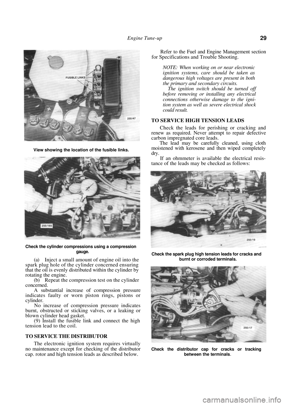
Check the cylinder compressions using a compression gauge.
(a) Inject a small amount of engine oil into the
spark plug hole of the cylinder concerned ensuring
that the oil is evenly distributed within the cylinder by
rotating the engine.
(b) Repeat the compression test on the cylinder
concerned.
A substantial increase of compression pressure
indicates faulty or worn piston rings, pistons or
cylinder.
No increase of compression pressure indicates
burnt, obstructed or sticking valves, or a leaking or
blown cylinder head gasket.
(9) Install the fusible li nk and connect the high
tension lead to the coil.
TO SERVICE THE DISTRIBUTOR
The electronic ignition system requires virtually
no maintenance except for checking of the distributor
cap. rotor and high tension leads as described below.
Refer to the Fuel and Engine Management section
for Specifications and Trouble Shooting.
NOTE: When working on or near electronic
ignition systems, care should be taken as
dangerous high voltages are present in both
the primary and secondary circuits.
The ignition switch should be turned off
before removing or inst alling any electrical
connections otherwise damage to the igni-
tion system as well as severe electrical shock
could result.
TO SERVICE HIGH TENSION LEADS
Check the leads for perishing or cracking and
renew as required. Never a ttempt to repair defective
carbon impregnated core leads.
The lead may be carefully cleaned, using cloth
moistened with kerosene a nd then wiped completely
dry.
If an ohmmeter is available the electrical resis-
tance of the leads may be checked as follows:
View showing the location of the fusible links.
Check the spark plug high tension leads for cracks and
burnt or corroded terminals.
Check the distributor cap for cracks or tracking
between the terminals
.
Page 35 of 238
Roadside Trouble Shooting 35
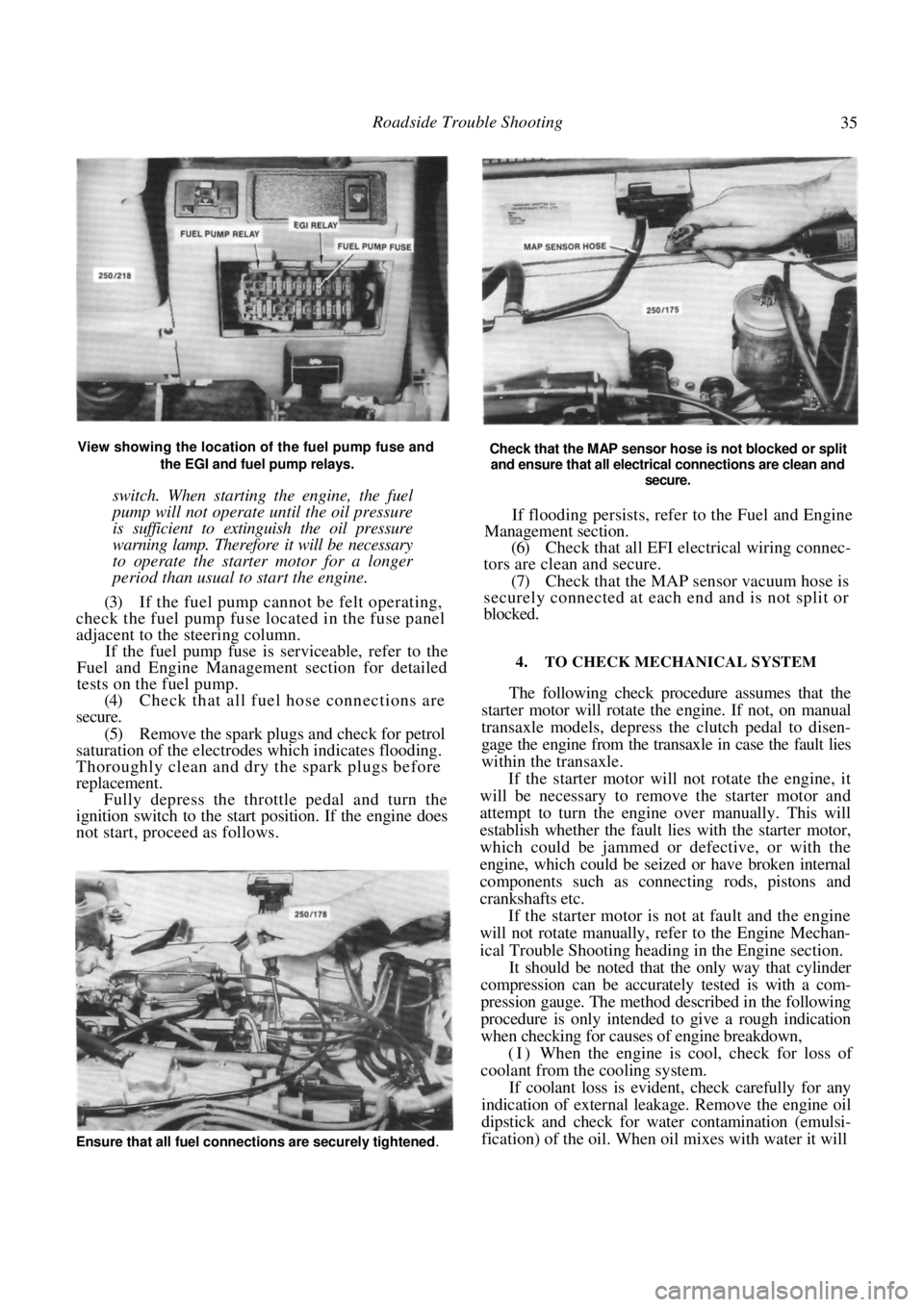
View showing the location of the fuel pump fuse and the EGI and fuel pump relays.
switch. When starting the engine, the fuel
pump will not operate until the oil pressure
is sufficient to extinguish the oil pressure
warning lamp. Therefore it will be necessary
to operate the starter motor for a longer
period than usual to start the engine.
(3) If the fuel pump cannot be felt operating,
check the fuel pump fuse located in the fuse panel
adjacent to the steering column.
If the fuel pump fuse is serviceable, refer to the
Fuel and Engine Management section for detailed
tests on the fuel pump.
(4) Check that all fuel hose connections are
secure.
(5) Remove the spark plugs and check for petrol
saturation of the electrodes which indicates flooding.
Thoroughly clean and dry the spark plugs before
replacement. Fully depress the throttle pedal and turn the
ignition switch to the start position. If the engine does
not start, proceed as follows.
Check that the MAP sensor hose is not blocked or split
and ensure that all electrical connections are clean and
secure.
If flooding persists, refer to the Fuel and Engine
Management section.
(6) Check that all EFI electrical wiring connec-
tors are clean and secure.
(7) Check that the MAP sensor vacuum hose is
securely connected at each end and is not split or
blocked.
4. TO CHECK MECHANICAL SYSTEM
The following check procedure assumes that the
starter motor will rotate the engine. If not, on manual
transaxle models, depress the clutch pedal to disen-
gage the engine from the tr ansaxle in case the fault lies
within the transaxle.
If the starter motor will not rotate the engine, it
will be necessary to remove the starter motor and
attempt to turn the engine over manually. This will
establish whether the fault lies with the starter motor,
which could be jammed or defective, or with the
engine, which could be seized or have broken internal
components such as connecting rods, pistons and
crankshafts etc.
If the starter motor is not at fault and the engine
will not rotate manually, refer to the Engine Mechan-
ical Trouble Shooting heading in the Engine section.
It should be noted that the only way that cylinder
compression can be accurately tested is with a com-
pression gauge. The method described in the following
procedure is only intended to give a rough indication
when checking for causes of engine breakdown,
(I) When the engine is cool, check for loss of
coolant from the cooling system.
If coolant loss is evident, check carefully for any
indication of external leakage. Remove the engine oil
dipstick and check for wate r contamination (emulsi-
fication) of the oil. When oil mixes with water it will
Ensure that all fuel connections are securely tightened.
Page 36 of 238
36 Roadside Trouble Shooting
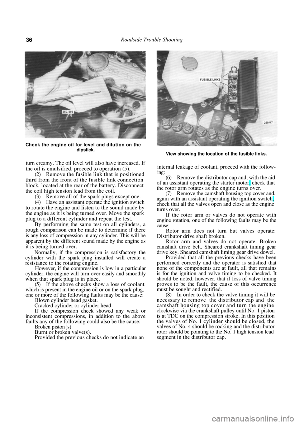
Check the engine oil for level and dilution on the dipstick.
turn creamy. The oil level will also have increased. If
the oil is emulsified, proceed to operation (5).
(2) Remove the fusible link that is positioned
third from the front of th e fusible link connection
block, located at the rear of the battery. Disconnect
the coil high tension lead from the coil. (3) Remove all of the spark plugs except one.
(4) Have an assistant operate the ignition switch
to rotate the engine and listen to the sound made by
the engine as it is being turned over. Move the spark
plug to a different cylinder and repeat the lest. By performing the same test on all cylinders, a
rough comparison can be made to determine if there
is any loss of compression in any cylinder. This will be
apparent by the different sound made by the engine as
it is being turned over.
Normally, if the compression is satisfactory the
cylinder with the spark plug installed will create a
resistance to the rotating engine.
However, if the compression is low in a particular
cylinder, the engine will tu rn over easily and smoothly
when that spark plug is in place.
(5) If the above checks show a loss of coolant
which is present in the engine oil or on the spark plug,
one or more of the following faults may be the cause:
Blown cylinder head gasket.
Cracked cylinder or cylinder head.
If the compression check showed any weak or
inconsistent compressions, in addition to the above
faults any of the following could also be the cause:
Broken piston{s)
Burnt or broken valve(s).
Provided the previous checks do not indicate an
View showing the location of the fusible links.
internal leakage of coolant, proceed with the follow-
ing:
(6) Remove the distributor cap and, with the aid
of an assistant operating th e starter motor, check that
the rotor arm rotates as the engine turns over. (7) Remove the camshaft hous ing top cover and.
again with an assistant operating the ignition switch,
check that all the valves open and close as the engine
turns over.
If the rotor arm or valves do not operate with
engine rotation, one of the following faults may be the
cause:
Rotor arm does not turn but valves operate:
Distributor drive shaft broken.
Rotor arm and valves do not operate: Broken
camshaft drive belt. Sheare d crankshaft timing gear
drive key. Sheared camshaft liming gear drive dowel.
Provided that all the previous checks have been
performed correctly and the operator is satisfied that
none of the components are at fault, all that remains
is for the ignition and valve timing to be checked. It
should be noted, however, that if loss of valve timing
proves to be the fault, th e cause of this occurrence
must be sought and rectified.
(8) In order to check the valve timing it will be
necessary to remove the distributor cap and the
camshaft housing top cover and turn the engine
clockwise via the crankshaft pulley until No. 1 piston
is at TDC on the compression stroke. In this position
the valves of No. 1 cylinder should be closed, the
valves of No. 4 should be rocking and the distributor
rotor should be pointing to the No. 1 high tension lead
segment in the distributor cap.
Page 37 of 238
37
ENGINE
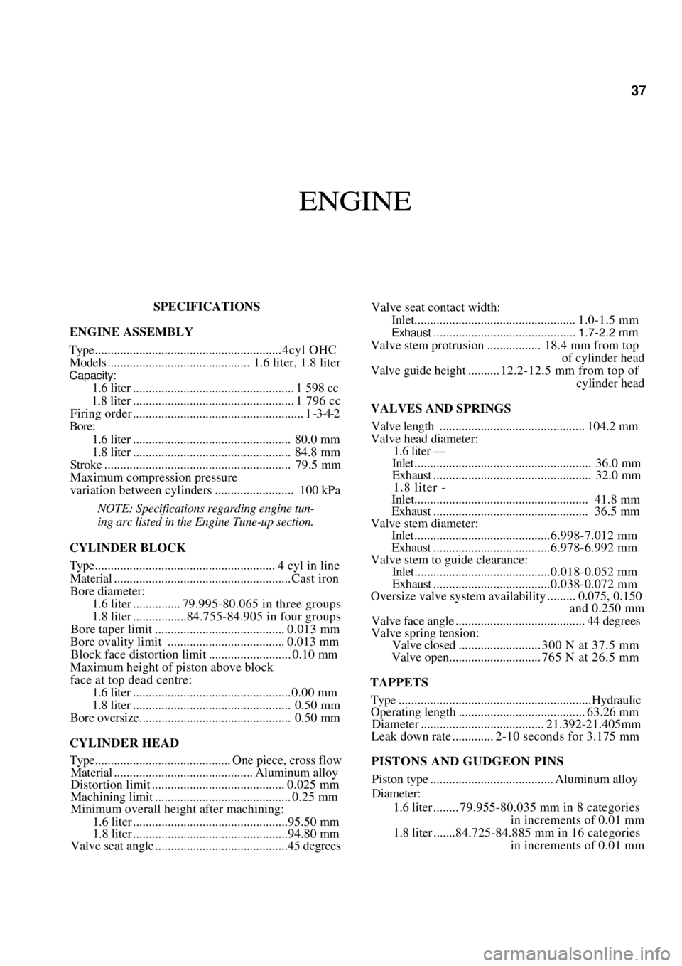
SPECIFICATIONS
ENGINE ASSEMBLY
Type........................................................... 4cyl OHC
Models ............................................. 1.6 liter, 1.8 liter
Capacity:
1.6 liter ................................................... 1 598 cc
1.8 liter ................................................... 1 796 cc
Firing order ...................................................... 1 -3-4-2
Bore:
1.6 liter.................................................. 80.0 mm
1.8 liter.................................................. 84.8 mm
Stroke ........................................................... 79.5 mm
Maximum compression pressure
variation between cylinders ......................... 100 kPa
NOTE: Specifications re garding engine tun-
ing arc listed in the Engine Tune-up section.
CYLINDER BLOCK
Type......................................................... 4 cyl in line
Material ........................................................ Cast iron
Bore diameter:
1.6 liter ............... 79. 995-80.065 in three groups
1.8 liter .................84. 755-84.905 in four groups
Bore taper limit ......................................... 0. 013 mm
Bore ovality limit ..................................... 0.013 mm
Block face distortion limit .......................... 0.10 mm
Maximum height of piston above block
face at top dead centre:
1.6 liter.................................................. 0.00 mm
1.8 liter.................................................. 0.50 mm
Bore oversize................................................ 0.50 mm
CYLINDER HEAD
Type........................................... One piece, cross flow
Material ............................................ Aluminum alloy
Distortion limit .......................................... 0.025 mm
Machining li mit ........................................... 0.25 mm
Minimum overall height after machining:
1.6 liter .................................................95.50 mm
1.8 liter .................................................94.80 mm
Valve seat angle ..........................................45 degrees
Valve seat contact width:
Inlet................................................... 1.0-1.5 mm
Exhaust ............................................. 1.7-2.2 mm
Valve stem protrusion ................. 18.4 mm from top
of cylinder head
Valve guide height .......... 12.2-12.5 mm from top of
cylinder head
VALVES AND SPRINGS
Valve length .............................................. 104. 2 mm
Valve head diameter:
1.6 liter —
Inlet........................................................ 36.0 mm
Exhaust .................................................. 32.0 mm
1.8 liter -
Inlet....................................................... 41.8 mm
Exhaust ................................................. 36.5 mm
Valve stem diameter:
Inlet...........................................6. 998-7.012 mm
Exhaust .....................................6.978-6.992 mm
Valve stem to guide clearance:
Inlet...........................................0.018-0.052 mm
Exhaust .....................................0.038-0.072 mm
Oversize valve system availability......... 0.075, 0.150
and 0.250 mm
Valve face angle ......................................... 44 degrees
Valve spring tension:
Valve closed .......................... 300 N at 37.5 mm
Valve open............................. 765 N at 26.5 mm
TAPPETS
Type .............................................................Hydraulic
Operating length ........................................ 63.26 mm
Diameter ....................................... 21.392-21.405mm
Leak down rate ............. 2-10 sec onds for 3.175 mm
PISTONS AND GUDGEON PINS
Piston type ....................................... Aluminum alloy
Diameter:
1.6 liter ........ 79. 955-80.035 mm in 8 categories
in increments of 0.01 mm
1.8 liter .......84.725-84.885 mm in 16 categories
in increments of 0.01 mm
Page 38 of 238
38 Engine
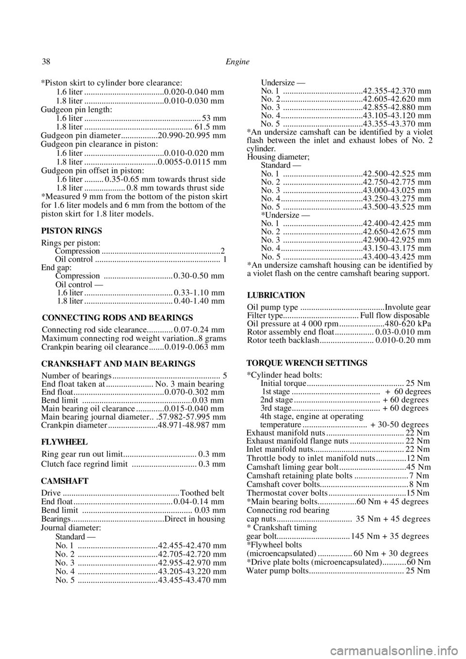
*Piston skirt to cylinder bore clearance:
1.6 liter .....................................0. 020-0.040 mm
1.8 liter .....................................0. 010-0.030 mm
Gudgeon pin length:
1.6 liter ...................................................... 53 mm
1.8 liter .................................................. 61.5 mm
Gudgeon pin diameter.................20.990-20.995 mm
Gudgeon pin clearance in piston:
1.6 liter .....................................0. 010-0.020 mm
1.8 liter ..................................0. 0055-0.0115 mm
Gudgeon pin offset in piston:
1.6 liter......... 0.35-0.65 mm towards thrust side
1.8 liter................... 0.8 mm towards thrust side
*Measured 9 mm from the bottom of the piston skirt
for 1.6 liter models and 6 mm from the bottom of the
piston skirt for 1.8 liter models.
PISTON RINGS
Rings per piston:
Compression .......................................................2
Oil contro l .......................................................... 1
End gap:
Compression ................................ 0.30-0.50 mm
Oil control —
1.6 liter ......................................... 0.33-1.10 mm
1.8 liter ......................................... 0.40-1.40 mm
CONNECTING RODS AND BEARINGS
Connecting rod side clearance............ 0.07-0.24 mm
Maximum connecting rod weight variation..8 grams
Crankpin bearing oil clearance ....... 0. 019-0.063 mm
CRANKSHAFT AND MAIN BEARINGS
Number of bearings .................................................. 5
End float taken at ...................... No. 3 main bearing
End float .......................................... 0.070-0.302 mm
Bend limit ...................................................0.03 mm
Main bearing oil clearance .............0. 015-0.040 mm
Main bearing journal diameter.. .57.982-57.995 mm
Crankpin diameter .......................48.971-48.987 mm
FLYWHEEL
Ring gear run out limit.................................. 0.3 mm
Clutch face regrind limit .............................. 0.3 mm
CAMSHAFT
Drive ...................................................... Toothed belt
End float .............................................. 0.04-0.14 mm
Bend limit ................................................... 0.03 mm
Bearings ...........................................Direct in housing
Journal diameter:
Standard —
No. 1 ..................................... 42. 455-42.470 mm
No. 2 ..................................... 42. 705-42.720 mm
No. 3 ..................................... 42.955-42.970 mm
No. 4 ..................................... 43.205-43.220 mm
No. 5 ..................................... 43.455-43.470 mm
Undersize —
No. 1 .....................................42.355-42.370 mm
No. 2 ......................................42.605-42.620 mm
No. 3 .....................................42.855-42.880 mm
No. 4 ......................................43.105-43.120 mm
No. 5 .....................................43. 355-43.370 mm
*An undersize camshaft can be identified by a violet
flash between the inlet and exhaust lobes of No. 2
cylinder.
Housing diameter;
Standard —
No. 1 .....................................42. 500-42.525 mm
No. 2 .....................................42.750-42.775 mm
No. 3 .....................................43.000-43.025 mm
No. 4 ......................................43.250-43.275 mm
No. 5 .....................................43.500-43.525 mm
*Undersize —
No. 1 .....................................42.400-42.425 mm
No. 2 .....................................42.650-42.675 mm
No. 3 .....................................42.900-42.925 mm
No. 4 ......................................43.150-43.175 mm
No. 5 .....................................43.400-43.425 mm
*An undersize camshaft housing can be identified by
a violet flash on the centre camshaft bearing support.
LUBRICATION
Oil pump type .......................................Involute gear
Filter type................................... Full flow disposable
Oil pressure at 4 000 rpm .....................480-620 kPa
Rotor assembly end float .................. 0.03-0. 010 mm
Rotor teeth backlash ......................... 0.010-0.20 mm
TORQUE WRENCH SETTINGS
*Cylinder head bolts:
Initial torque ............................................. 25 Nm
1st stage ......................................... + 60 degrees
2nd stage ........................................ + 60 degrees
3rd stage......................................... + 60 degrees
4th stage, engine at operating
temperature .............................. + 30-50 degrees
Exhaust manifold nuts .................................... 22 Nm
Exhaust manifold flange nuts ......................... 22 Nm
Inlet manifold nuts.......................................... 22 Nm
Throttle body to inlet manifold nuts ..............12 Nm
Camshaft liming gear bolt ...............................45 Nm
Camshaft retainin g plate bolts ......................... 7 Nm
Camshaft cover bolts......................................... 8 Nm
Thermostat cover bolts ....................................15 Nm
*Main bearing bolts..................60 Nm + 45 degrees
Connecting rod bearing
cap nuts ................................... 35 Nm + 45 degrees
* Crankshaft timing
gear bolt.................................. 145 Nm + 35 degrees
*Flywheel bolts
(microencapsulated) ................ 60 Nm + 30 degrees
*Drive plate bolts (microencapsulated)........... 60 Nm
Water pump bolts............................................ 25 Nm
Page 39 of 238
Engine 39
Oil pump cover plate screws............................ 6 Nm
Oil pump mounting bolts.................................. 6 Nm
Oil pump pickup bolts
(coat with Loctite 242)..................................... 8 Nm
Sump bolts (coat with Loctite 242) .................. 5 Nm
Sump drain plug .............................................. 35 Nm
*Use new bolts
Head bolts maximum torque 135 Nm
1. ENGINE MECHANICAL TROUBLE
SHOOTING
ENGINE MISSES AT IDLING SPEED
NOTE: For other causes of engine misfire,
refer to the Fuel and Engine Management
section.
(1) Blown head gasket: Check the cylinder com-
pressions and renew the he ad gasket as necessary.
(2) Burnt valves or seats in the cylinder head:
Check the cylinder compressions and overhaul the
cylinder head as necessary. (3) Broken or worn piston rings: Check the
cylinder compressions and renew the piston rings as
necessary.
(4) Weak or broken valve springs: Remove the
camshaft housing top cover and check the condition
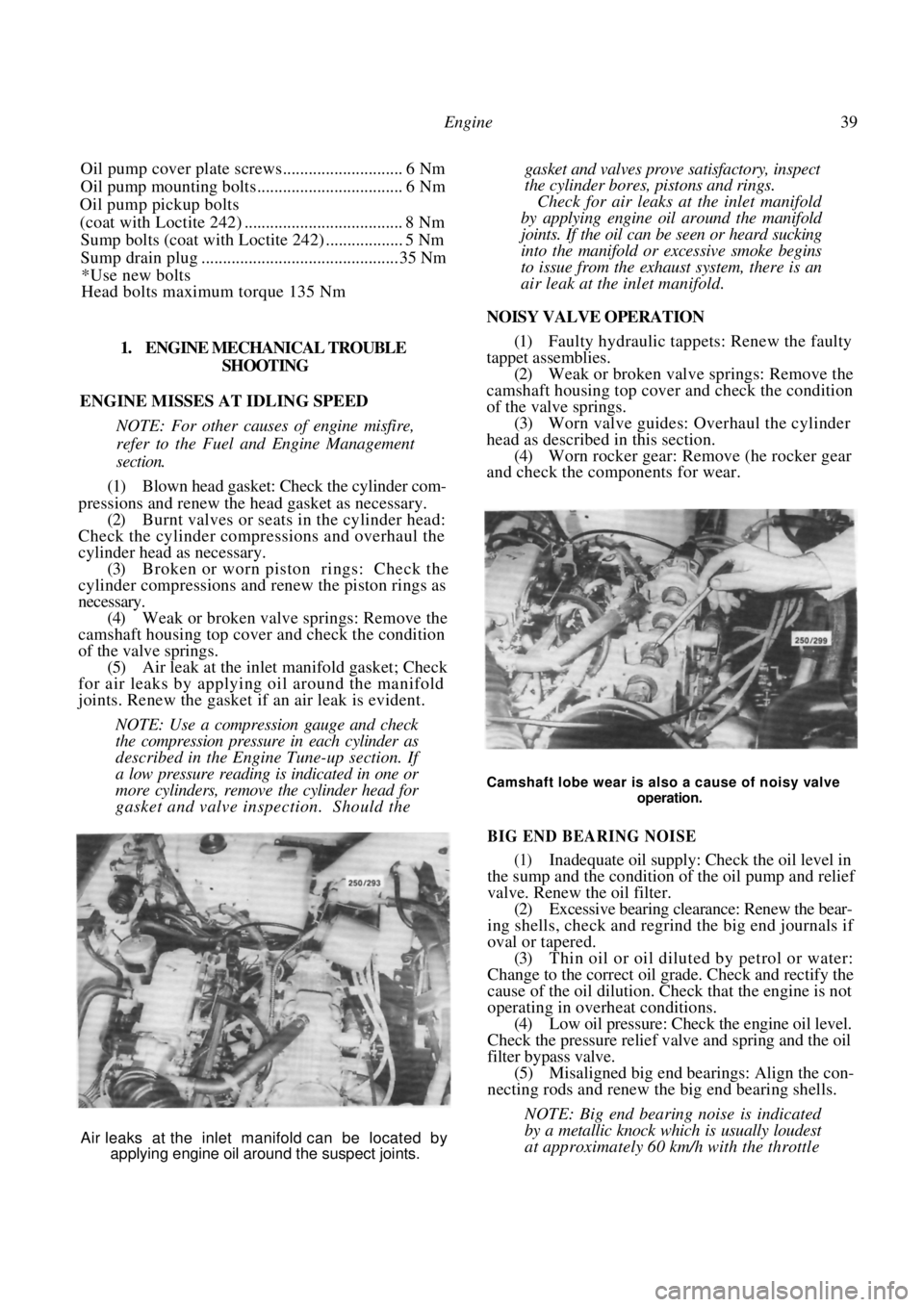
of the valve springs. (5) Air leak at the inlet manifold gasket; Check
for air leaks by applying oil around the manifold
joints. Renew the gasket if an air leak is evident.
NOTE: Use a compre ssion gauge and check
the compression pressure in each cylinder as
described in the Engine Tune-up section. If
a low pressure reading is indicated in one or
more cylinders, remove the cylinder head for
gasket and valve inspection. Should the
gasket and valves prove satisfactory, inspect
the cylinder bores, pistons and rings.
Check for air leaks at the inlet manifold
by applying engine oil around the manifold
joints. If the oil can be seen or heard sucking
into the manifold or excessive smoke begins
to issue from the exhaust system, there is an
air leak at the inlet manifold.
NOISY VALVE OPERATION
(1) Faulty hydraulic tappets: Renew the faulty
tappet assemblies. (2) Weak or broken valve springs: Remove the
camshaft housing top cover and check the condition
of the valve springs. (3) Worn valve guides: Overhaul the cylinder
head as described in this section. (4) Worn rocker gear: Remove (he rocker gear
and check the components for wear.
Camshaft lobe wear is also a cause of noisy valve
operation.
BIG END BEARING NOISE
(1) Inadequate oil supply: Check the oil level in
the sump and the condition of the oil pump and relief
valve. Renew the oil filter.
(2) Excessive bearing clearance: Renew the bear-
ing shells, check and regrind the big end journals if
oval or tapered. (3) Thin oil or oil diluted by petrol or water:
Change to the correct oil grade. Check and rectify the
cause of the oil dilution. Ch eck that the engine is not
operating in overheat conditions.
(4) Low oil pressure: Check the engine oil level.
Check the pressure relief valve and spring and the oil
filter bypass valve. (5) Misaligned big end bearings: Align the con-
necting rods and renew the big end bearing shells.
NOTE: Big end bearing noise is indicated
by a metallic knock wh ich is usually loudest
at approximately 60 km/h with the throttle
Air leaks at the inlet manifold can be located by
applying engine oil around the suspect joints.
Page 40 of 238
40 Engine
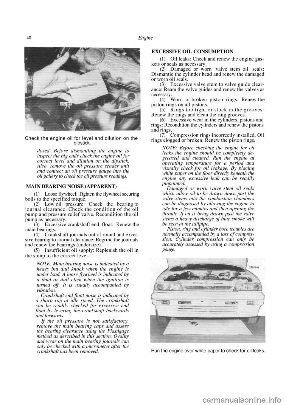
Check the engine oil for level and dilution on the dipstick.
dosed. Before dismantling the engine to
inspect the big ends check the engine oil for
correct level and dilution on the dipstick.
Also, remove the oil pressure sender unit
and connect an oil pressure gauge into the
oil gallery to check the oil pressure readings.
MAIN BEARING NOISE (APPARENT)
(1) Loose flywheel: Tighten the flywheel securing
bolls to the specified torque. (2) Low oil pressure: Check the bearing to
journal clearance. Check the condition of the oil
pump and pressure relief valve. Recondition the oil
pump as necessary. (3) Excessive crankshaft end float: Renew the
main bearings. (4) Crankshaft journals out of round and exces-
sive bearing to journal clear ance: Regrind the journals
and renew the bearings (undersize).
(5) Insufficient oil supply: Replenish the oil in
the sump to the correct level.
NOTE: Main bearing noise is indicated by a
heavy but dull knock when the engine is
under load. A loose flywheel is indicated by
a thud or dull click when the ignition is
turned off. It is us ually accompanied by
vibration.
Crankshaft end float noise is indicated by
a sharp rap at idle speed. The crankshaft
can be readily checked for excessive end
float by levering the crankshaft backwards
and forwards.
If the oil pressure is not satisfactory,
remove the main bearing caps and assess
the bearing clearance using the Plastigage
method as described in this section. Ovality
and wear on the main bearing journals can
only be checked with a micrometer after the
crankshaft has been removed.
EXCESSIVE OIL CONSUMPTION
(1) Oil leaks: Check and renew the engine gas-
kets or seals as necessary.
(2) Damaged or worn valve stem oil seals:
Dismantle the cylinder head and renew the damaged
or worn oil seals. (3) Excessive valve stem to valve guide clear-
ance: Ream the valve guides and renew the valves as
necessary. (4) Worn or broken piston rings: Renew the
piston rings on all pistons. (5) Rings too tight or stuck in the grooves:
Renew the rings and clean the ring grooves.
(6) Excessive wear in the cylinders, pistons and
rings: Recondition the cylinders and renew the pistons
and rings. (7) Compression rings incorrectly installed. Oil
rings clogged or broken: Renew the piston rings.
NOTE: Before checking the engine for oil
leaks the engine should be completely de-
greased and cleaned. Run the engine at
operating temperature for a period and
visually check for oil leakage. By placing
white paper on the floor directly beneath the
engine any excessive leak can be readily
pinpointed.
Damaged or worn valve stem oil seals
which allow oil to be drawn down past the
valve stems into the combustion chambers
can be diagnosed by allowing the engine to
idle for a few minutes and then opening the
throttle. If oil is being drawn past the valve
stems a heavy discharge of blue smoke will
be seen at the tailpipe.
Piston, ring and cylinder bore troubles are
normally accompanied by a loss of compres-
sion. Cylinder compression can only be
accurately assessed by using a compression
gauge.
Run the engine over white paper to check for oil leaks.