dimensions NISSAN PULSAR 1987 Workshop Manual
[x] Cancel search | Manufacturer: NISSAN, Model Year: 1987, Model line: PULSAR, Model: NISSAN PULSAR 1987Pages: 238, PDF Size: 28.91 MB
Page 47 of 238

Engine 47
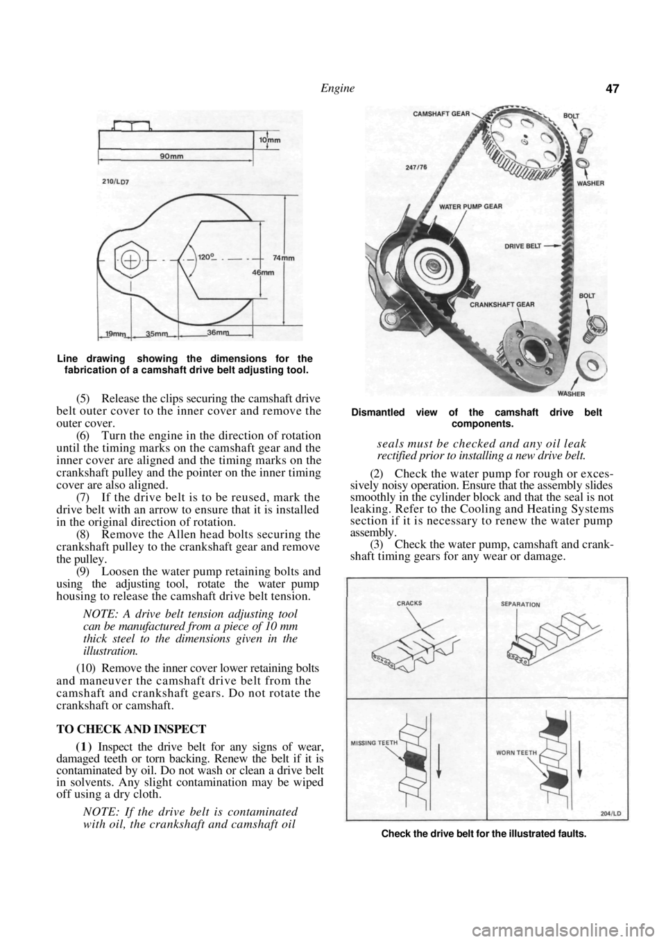
Line drawing showing the dimensions for the fabrication of a camshaft drive belt adjusting tool.
(5) Release the clips securing the camshaft drive
belt outer cover to the inner cover and remove the
outer cover.
(6) Turn the engine in the direction of rotation
until the timing marks on the camshaft gear and the
inner cover are aligned and the timing marks on the
crankshaft pulley and the pointer on the inner timing
cover are also aligned.
(7) If the drive belt is to be reused, mark the
drive belt with an arrow to ensure that it is installed
in the original direction of rotation. (8) Remove the Allen head bolts securing the
crankshaft pulley to the crankshaft gear and remove
the pulley. (9) Loosen the water pump retaining bolts and
using the adjusting tool, rotate the water pump
housing to release the camsh aft drive belt tension.
NOTE: A drive belt tension adjusting tool
can be manufactured from a piece of 10 mm
thick steel to the dimensions given in the
illustration.
(10) Remove the inner cover lower retaining bolts
and maneuver the camshaft drive belt from the
camshaft and crankshaft gears. Do not rotate the
crankshaft or camshaft.
TO CHECK AND INSPECT
(1) Inspect the drive belt for any signs of wear,
damaged teeth or torn backing. Renew the belt if it is
contaminated by oil. Do not wash or clean a drive belt
in solvents. Any slight contamination may be wiped
off using a dry cloth.
NOTE: If the drive belt is contaminated
with oil, the crankshaft and camshaft oil
Dismantled view of the camshaft drive belt
components.
seals must be checked and any oil leak
rectified prior to installing a new drive belt.
(2) Check the water pump for rough or exces-
sively noisy operation. Ensure that the assembly slides
smoothly in the cylinder bloc k and that the seal is not
leaking. Refer to the Cooling and Heating Systems
section if it is necessary to renew the water pump
assembly. (3) Check the water pump, camshaft and crank-
shaft timing gears for any wear or damage.
Check the drive belt for the illustrated faults.
Page 100 of 238

100 Fuel and Engine Management
Installation is a reversal of the removal procedure
with attention to the following points:
(1) Ensure that all throttle body passages are
clean. Blow out with compressed air if necessary. (2) Install the throttle body to the inlet
manifold
using a new gasket and tighten the retaining nuts to
the specified torque. (3) Connect the vacuum hoses to the throttle
body in the positions previously marked. (4) Clip the actuating rod to the throttle body
lever. Check the dimensions shown in the illustration
and adjust the rod length if necessary.
(5) Check the adjustment of the throttle cable as
described later in this section.
(6) Connect the air intake hose and tighten the
hose clamps securely.
To Remove and Install — 1.6 Liter Engine
(1) Depressurize the fuel system as previously
described. (2) Disconnect the negative battery terminal.
(3) Remove the air cleane r assembly and base
gasket as previously described. (4) Mark the fuel supply and return hoses,
release the clamps and disconnect the hoses from the
throttle body assembly. (5) Disconnect the injector, throttle position
sensor and the IAC valve wiring connectors. Remove
the injector wiring harness from the throttle body
assembly and place it to one side.
(6) Mark and disconnect the vacuum hoses from
the throttle body assembly. (7) On automatic transaxle models, disconnect
the kickdown actuating rod from the throttle linkage.
(8) Slide the outer throttle cable from the
mounting bracket, rotate the throttle linkage and disconnect the inner throttle cable from the throttle
linkage.
(9)
Remove the bolts retaining the throttle body
assembly to the inlet manifold and remove the
assembly and the gasket from the engine. (10) If necessary remove the retaining screws and
remove the fuel meter assembly, the IAC valve and
the throttle position sensor from the throttle body
assembly. Installation is a reversal of the removal procedure
with attention to the following points:
(1) If removed, install the fuel meter assembly,
the throttle position sensor and the IAC valve as
described under the relevant headings. (2) Install the throttle body assembly to the inlet
manifold using a new gasket and tighten the retaining
bolts to the specified torque. (3) Connect the vacuum ho ses to the throttle
body using the marks made on removal to ensure
correct installation. (4) On automatic transaxle models, connect the
kickdown actuating rod to the throttle linkage.
(5) Install the throttle cable and check the adjust-
ment as described later in this section.
INLET MANIFOLD
To Remove and Install
To remove and install the inlet manifold, refer to
the relevant heading in the Engine section.
IDLE AIR CONTROL (IAC) VALVE
To Test
(1) Connect an accurate tachometer to the en-
gine. (2) With the engine at normal operating temper-
ature and all accessories switched Off, note the idle
speed.
(3) With the ignition switched Off, disconnect
the IAC valve wiring connector. (4) Start the engine and check the idle speed.
If the idle speed is the same as that noted in
operation (2) proceed to operation (7).
If the idle speed is higher than noted in operation
(2) proceed as follows.
(5) With the ignition switched Off, connect the
IAC valve wiring connector.
(6) Start the engine and check the idle speed.
If the idle speed is not the same as that noted in
operation (2) proceed to operation (7).
If the idle speed is the same as noted in operation
(2) the IAC valve is operating correctly. However, if
the engine is not idling correctly carry out the
following checks.
(a) Check the air inlet system for vacuum leaks.
NOTE: Any vacuum leak will cause a fast
idle.
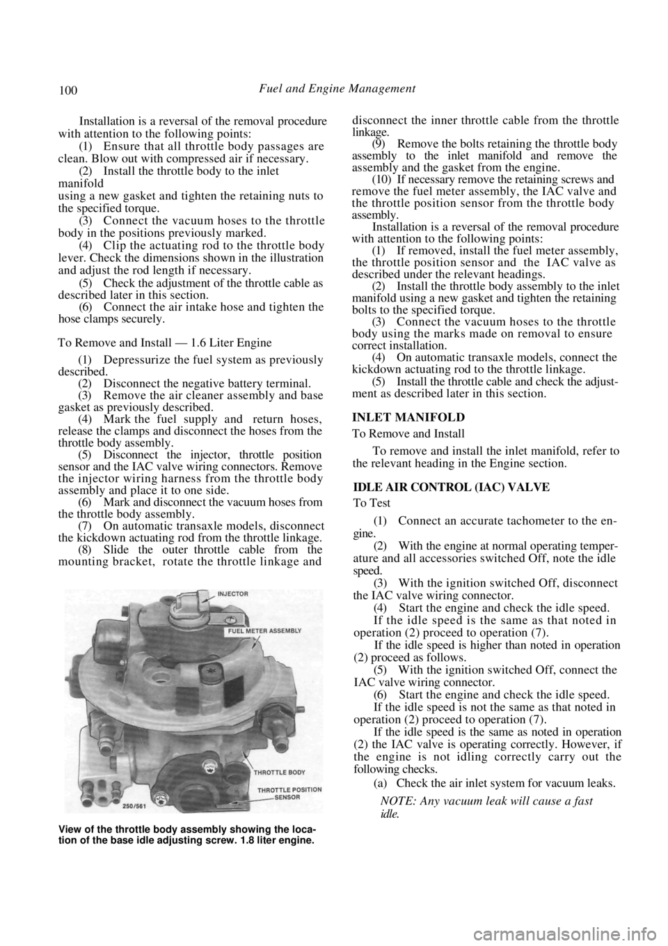
View of the throttle body assembly showing the loca-
tion of the base idle adjusting screw. 1.8 literengine.
Page 209 of 238

Electrical System 209
12. INSTRUMENT CLUSTER
TO REMOVE AND INSTAL
Disconnect the negative battery terminal.
Remove the retaining screws from the instru-
ment cluster surround. Carefully withdraw the instrument cluster
surround from the instrument panel sufficiently to
enable the wiring to be disconnected. Remove the
surround from the vehicle.
.
FLEXIBLE PRINTED
CIRCUIT
Rear view of the instrument cluster removed from the
vehicle.
(4) Remove the instrument cluster assembly
retaining screws and gently ease the assembly from the
instrument panel sufficiently to enable the wiring to be
disconnected.
If necessary, remove the instruments as follows:
Carefully depress the retaining clips on the
front lens and remove the front lens. On models equipped with a tachometer, slide
the plastic rib from between the speedometer and the
tachometer. Remove the screws retaining the speedome-
ter and the tachometer or fuel/temperature gauges
from the rear of the instrument cluster.
CLUSTER ASSEMBLY
(d) Withdraw both instruments from the front of
the instrument cluster being careful as these instru-
ments are held by protruding pin terminals.
NOTE: Do not touch the faces of the instru-
ment dials as they mark easily.
(e) On models equipped with a tachometer,
remove the retaining nuts and remove the tempera-
ture and/or the fuel gauge from the cluster assembly.
Installation is a reversal of the removal procedure
ensuring that all electrical connectors are correctly
installed.
13. BLOWER FAN
The removal and installation procedure for the
blower fan is described in the Cooling and Heating
Systems section.
14. RADIO/CASSETTE
TO REMOVE AND INSTAL
Disconnect the negative battery terminal.
Remove the release hole covers on each side
of the radio/cassette.
Dismantled view of the instrument cluster.
Illustration of the radio/cass ette removal tool showing
the required dimensions.
BULB HOLDERS
BULB HOLDERS
Removing the release hole covers from the radio/cas-
sette.
Page 234 of 238

234 Body
LOCK ASSEMBLY
To Remove and Install
( 1 ) Remove the retaining bolts and withdraw the
lock assembly from the luggage compartment lid.
Installation is a reversal of the removal procedure
ensuring that the actuating arm on the lock is under
the lock cylinder pivot.
LOCK CYLINDER
Installed view of the lock and lock cylinder.
LOCK CYLINDER
To Remove and Install
Remove the bolt retaining the lock cylinder
pivot to the luggage compartment lid inner panel. Using a suitable screwdriver, remove the
lock cylinder retaining clip from under the lock. Withdraw the lock cylinder and pivot from
the vehicle. Installation is a reversal of the removal procedure.
(2) When the clips have been released, pull the
grille forward and remove it from the vehicle ensuring
that care is taken not to damage the grille.
Installation is a reversal of the removal procedure
with attention to the following points:
Remove the grille retaining clips from the
radiator support panel and install them to the
grille.
Renew any damaged clips. Install the grille to the vehicle being careful to
align the grille clips before pushing the grille inwards.
Post July 1989 Pulsar Models
Fabricate a tool to engage the radiator grille
clips from the inside; an old spanner of suitable
dimensions can be ground down if necessary.
Using the above tool, turn the lower radiator
clips slightly to allow removal of the grille.
7. RADIATOR GRILLE
TO REMOVE AND INSTAL
Astra Models and Pre July 1989 Pulsar Models
(1) Using a flat bladed screwdriver, turn the
grille clips slightly to allow removal of the grille.
Installed view of the radiator grille on pre July 1989
models showing the retaining clip locations. Installed view of the radiator grille on post July 1989
models showing the retaining clip locations and the
special tool required to release the lower clips.
Using a flat bladed screwdriver, turn the
upper grille clips slightly to allow removal of the grille. When all the clips have been released, pull
the grille forward and remove it from the vehicle
ensuring that care is taken not to damage the grille.
Installation is a reversal of the removal procedure
with attention to the following points:
Remove the grille clips from the radiator
support panel and install them to the grille. Renew any
damaged clips.
Install the grille to the vehicle being careful to
align the grille clips before pushing the grille inwards.
8. CENTRE CONSOLE
TO REMOVE AND INSTAL
Remove the carpet square from the rear part
of the console and remove the screws underneath. Prise out the trim piece below the handbrake