stop start NISSAN PULSAR 1987 Workshop Manual
[x] Cancel search | Manufacturer: NISSAN, Model Year: 1987, Model line: PULSAR, Model: NISSAN PULSAR 1987Pages: 238, PDF Size: 28.91 MB
Page 15 of 238
Lubrication and Maintenance 15
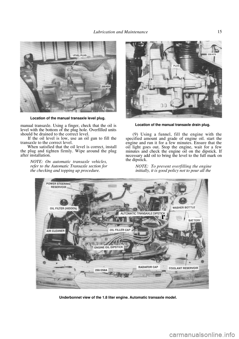
Location of the manual transaxle level plug.
manual transaxle. Using a finger, check that the oil is
level with the bottom of the plug hole. Overfilled units
should be drained to the correct level.
If the oil level is low, use an oil gun to fill the
transaxle to the correct level.
When satisfied that the oil level is correct, install
the plug and tighten firmly. Wipe around the plug
after installation.
NOTE: On automatic transaxle vehicles,
refer to the Automatic Transaxle section for
the checking and topping up procedure.
Location of the manual transaxle drain plug.
(9) Using a funnel, fill the engine with the
specified amount and grade of engine oil. start the
engine and run it for a few minutes. Ensure that the
oil light goes out. Stop the engine, wait for a few
minutes and check the engine oil on the dipstick. If
necessary add oil to bring the level to the full mark on
the dipstick.
NOTE: To prevent overfilling the engine
initially, it is good policy not to pour all the
Underbonnet view of the 1.8 liter engine. Automatic transaxle model.
AUTOMATIC TRANSAXLE DIPSTICK
r
Page 28 of 238
Engine Tune-up
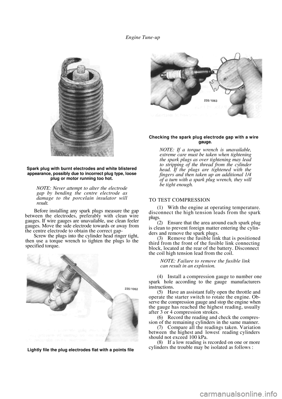
Spark plug with burnt electrodes and white blistered
appearance, possibly due to incorrect plug type, loose
plug or motor running too hot.
NOTE: Never attempt to alter the electrode
gap by bending the centre electrode as
damage to the porcelain insulator will
result.
Before installing any spark plugs measure the gap
between the electrodes, pref erably with clean wire
gauges. If wire gauges are una vailable, use clean feeler
gauges. Move the side electrode towards or away from
the centre electrode to obtain the correct gap-
Screw the plugs into the cylinder head ringer tight,
then use a torque wrench to tighten the plugs lo the
specified torque.
Checking the spark plug electrode gap with a wire
gauge.
NOTE: If a torque wrench is unavailable,
extreme care must be taken when tightening
the spark plugs as over tightening may lead
to stripping of the thread from the cylinder
head. If the plugs are tightened with the
fingers and then taken up an additional 1/4
of a turn with a spark plug wrench, they will
be tight enough.
TO TEST COMPRESSION
(1) With the engine at operating temperature.
disconnect the high tension leads from the spark
plugs.
(2) Ensure that the area around each spark plug
is clean to prevent foreign matter entering the cylin-
ders and remove the spark plugs. (3) Remove the fusible link that is positioned
third from the front of th e fusible link connecting
block, located at the rear of the battery. Disconnect
the coil high tension lead from the coil.
NOTE: Failure to remove the fusible link
can result in an explosion.
(4) Install a compression gauge to number one
spark hole according to the gauge manufacturers
instructions. (5) Have an assistant fully open the throttle and
operate the starter switch to rotate the engine. Ob-
serve the compression gauge and stop the engine when
the gauge has reached the highest reading, usually
after 3 or 4 compression strokes.
(6) Record the reading a nd check the compres-
sion of the remaining cylinders in the same manner.
(7) Compare all the readings taken. Variation
between the highest and lowest reading cylinders
should not exceed 100 kPa. (8) If a low reading is recorded on one or more
cylinders the trouble may be isolated as follows :
Lightly file the plug electrodes flat with a points file
Page 91 of 238
Fuel and Engine Management 91
components, erase the self diagnosis memory as
described under the following heading.
(7) Repeat the self diagnosis test procedure and
ensure that code 12 is displayed.
To Erase Memory
(1) With the ignition Off, remove the fusible link
that is positioned third from the front of the fusible
link connecting block located at the rear of the
battery. (2) Install the fusible link after 10 seconds.
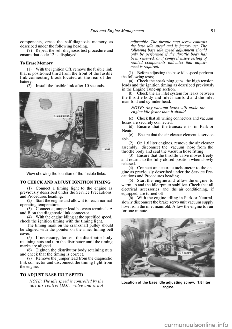
View showing the location of the fusible links.
TO CHECK AND ADJUST IGNITION TIMING
(1) Connect a timing light to the engine as
previously described under the Service Precautions
and Procedures heading.
(2) Start the engine and allow it to reach normal
operating temperature. (3) Connect a jumper lead between terminals A
and B on the diagnostic link connector. (4) With the engine idling at the specified speed,
check the ignition timing with the timing light.
The timing mark on the crankshaft pulley should
be aligned with the pointer on the inner liming belt
cover.
(5) If necessary, loosen the distributor body
retaining nuts and turn the distributor until the timing
marks are aligned. (6) Tighten the distributor body retaining nuts
and check that the timing is correct. (7) Remove the jumper lead from the diagnostic
link connector and disconnect the timing light from
the engine.
TO ADJUST BASE IDLE SPEED
NOTE: The idle speed is controlled by the
idle air control (IAC) valve and is not
adjustable. The throttle stop screw controls
the base idle speed a nd is factory set. The
following base idle speed adjustment should
only be performed if the throttle body has
been renewed, or if comprehensive testing of
related components indicates that adjust-
ment is required.
(1) Before adjusting the base idle speed perform
the following tests;
(a) Check the spark plug gaps, the high tension
leads and the ignition timin g as described previously
in the Engine Tune-up section.
(b) Check the air inlet syst em for leaks between
the throttle body and inlet manifold and the inlet
manifold and cylinder head.
NOTE; Any vacuum leaks will make the
engine idle faster than it should.
(c) Check that all wiring connectors and vacuum
hoses are securely connected. (d) Ensure that the transaxle is in Park or
Neutral. (e) Ensure that the air cleaner element is service-
able.
(2) On 1.6 liter engines, remove the air cleaner
assembly, disconnect the vacuum hose from the
throttle body and seal the vacuum hose fitting.
(3) Ensure that the throttle valve moves freely
and returns to the fully closed position when slowly
released. (4) Connect an accurate tachometer to the en-
gine as previously descri bed under the Service Pre-
cautions and Procedures heading.
(5) Start the engine and allow the engine to
warm up and the idle rpm to stabilize. Check that all
electrical accessories and the air conditioning, if
equipped, are turned off. (6) With the engine idling in Park or Neutral,
slowly disconnect the brake servo unit vacuum supply
hose from the inlet manifold. Allow the engine to run
for one minute.
Location of the base idle adjusting screw. 1.8 liter
engine.
Page 92 of 238
92 Fuel and Engine Management
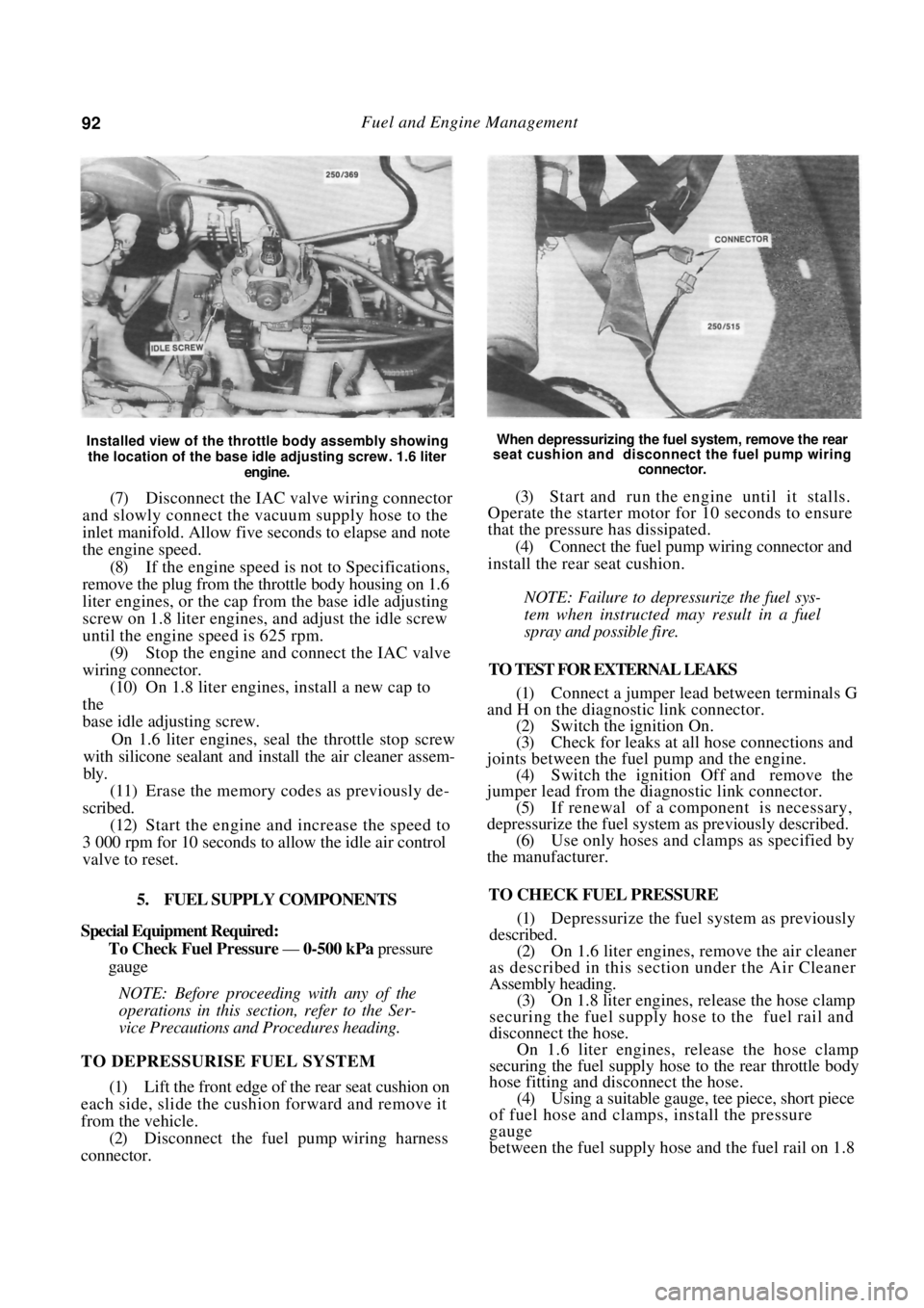
Installed view of the throttle body assembly showing
the location of the base idle adjusting screw. 1.6 liter
engine.
(7) Disconnect the IAC valve wiring connector
and slowly connect the vacuum supply hose to the
inlet manifold. Allow five seconds to elapse and note
the engine speed.
(8) If the engine speed is not to Specifications,
remove the plug from the throttle body housing on 1.6
liter engines, or the cap from the base idle adjusting
screw on 1.8 liter engines, and adjust the idle screw
until the engine speed is 625 rpm. (9) Stop the engine and connect the IAC valve
wiring connector. (10) On 1.8 liter engines, install a new cap to
the
base idle adjusting screw.
On 1.6 liter engines, seal the throttle stop screw
with silicone sealant and install the air cleaner assem-
bly.
(11) Erase the memory codes as previously de-
scribed.
(12) Start the engine and increase the speed to
3 000 rpm for 10 seconds to allow the idle air control
valve to reset.
5. FUEL SUPPLY COMPONENTS
Special Equipment Required:
To Check Fuel Pressure — 0-500 kPa pressure
gauge
NOTE: Before proceeding with any of the
operations in this section, refer to the Ser-
vice Precautions and Procedures heading.
TO DEPRESSURISE FUEL SYSTEM
(1) Lift the front edge of the rear seat cushion on
each side, slide the cushion forward and remove it
from the vehicle. (2) Disconnect the fuel pump wiring harness
connector.
When depressurizing the fuel system, remove the rear
seat cushion and disconnect the fuel pump wiring
connector.
(3) Start and run the engine until it stalls.
Operate the starter motor for 10 seconds to ensure
that the pressure has dissipated.
(4) Connect the fuel pump wiring connector and
install the rear seat cushion.
NOTE: Failure to depressurize the fuel sys-
tem when instructed may result in a fuel
spray and possible fire.
TO TEST FOR EXTERNAL LEAKS
(1) Connect a jumper lead between terminals G
and H on the diagnostic link connector.
(2) Switch the ignition On.
(3) Check for leaks at all hose connections and
joints between the fuel pump and the engine. (4) Switch the ignition Off and remove the
jumper lead from the diagnostic link connector.
(5) If renewal of a component is necessary,
depressurize the fuel system as previously described. (6) Use only hoses and clamps as specified by
the manufacturer.
TO CHECK FUEL PRESSURE
(1) Depressurize the fuel system as previously
described. (2) On 1.6 liter engines, remove the air cleaner
as described in this section under the Air Cleaner
Assembly heading. (3) On 1.8 liter engines, release the hose clamp
securing the fuel supply hos e to the fuel rail and
disconnect the hose. On 1.6 liter engines, release the hose clamp
securing the fuel supply hose to the rear throttle body
hose fitting and disconnect the hose.
(4) Using a suitable gauge, tee piece, short piece
of fuel hose and clamps, install the pressure
gauge
between the fuel supply ho se and the fuel rail on 1.8
Page 102 of 238
\(V2 Fuel and Engine Management
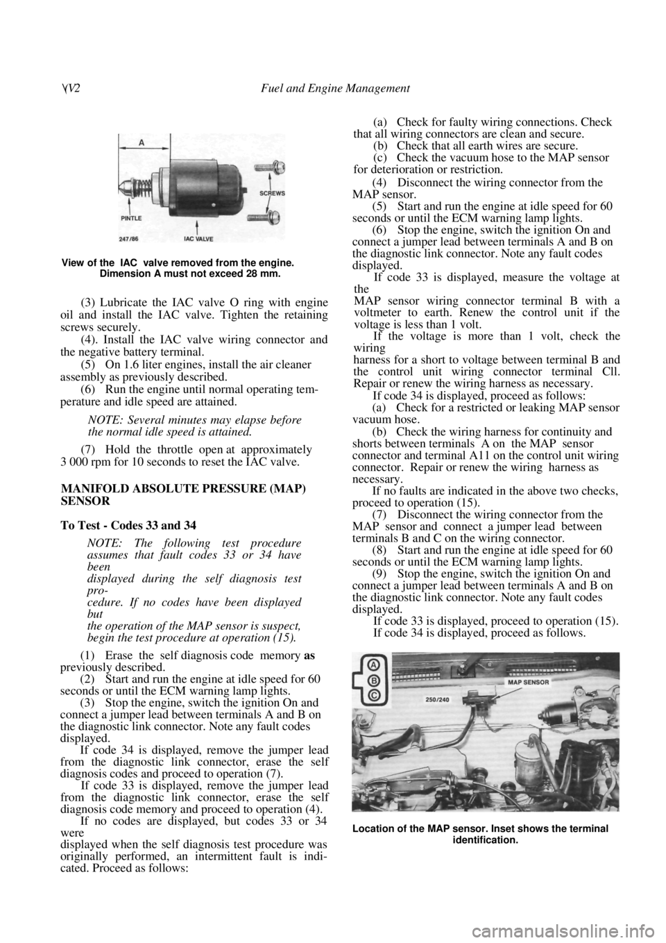
View of the IAC valve removed from the engine. Dimension A must not exceed 28 mm.
(3) Lubricate the IAC valve O ring with engine
oil and install the IAC valve. Tighten the retaining
screws securely.
(4). Install the IAC valve wiring connector and
the negative battery terminal.
(5) On 1.6 liter engines, install the air cleaner
assembly as previously described. (6) Run the engine until normal operating tem-
perature and idle speed are attained.
NOTE: Several minutes may elapse before
the normal idle speed is attained.
(7) Hold the throttle open at approximately
3 000 rpm for 10 seconds to reset the IAC valve.
MANIFOLD ABSOLUTE PRESSURE (MAP)
SENSOR
To Test - Codes 33 and 34
NOTE: The following test procedure
assumes that fault codes 33 or 34 have
been
displayed during the self diagnosis test
pro-
cedure. If no codes have been displayed
but
the operation of the MAP sensor is suspect,
begin the test procedure at operation (15).
(1) Erase the self diagnosis code memory as
previously described.
(2) Start and run the engine at idle speed for 60
seconds or until the ECM warning lamp lights.
(3) Stop the engine, switch the ignition On and
connect a jumper lead between terminals A and B on
the diagnostic link connector. Note any fault codes
displayed. If code 34 is displayed, remove the jumper lead
from the diagnostic link connector, erase the self
diagnosis codes and proceed to operation (7).
If code 33 is displayed, remove the jumper lead
from the diagnostic link connector, erase the self
diagnosis code memory and proceed to operation (4).
If no codes are displayed, but codes 33 or 34
were
displayed when the self diagnosis test procedure was
originally performed, an intermittent fault is indi-
cated. Proceed as follows:
(a) Check for faulty wiring connections. Check
that all wiring connectors are clean and secure. (b) Check that all earth wires are secure.
(c) Check the vacuum hose to the MAP sensor
for deterioration or restriction.
(4) Disconnect the wiring connector from the
MAP sensor. (5) Start and run the engine at idle speed for 60
seconds or until the ECM warning lamp lights. (6) Stop the engine, switch the ignition On and
connect a jumper lead between terminals A and B on
the diagnostic link connector. Note any fault codes
displayed.
If code 33 is displayed, measure the voltage at
the
MAP sensor wiring connector terminal B with a
voltmeter to earth. Renew the control unit if the
voltage is less than 1 volt.
If the voltage is more than 1 volt, check the
wiring
harness for a short to voltage between terminal B and
the control unit wiring connector terminal Cll.
Repair or renew the wiring harness as necessary.
If code 34 is displayed, proceed as follows:
(a) Check for a restricted or leaking MAP sensor
vacuum hose.
(b) Check the wiring harness for continuity and
shorts between terminals A on the MAP sensor
connector and terminal A11 on the control unit wiring
connector. Repair or renew the wiring harness as
necessary.
If no faults are indicated in the above two checks,
proceed to operation (15).
(7) Disconnect the wiring connector from the
MAP sensor and connect a jumper lead between
terminals B and C on the wiring connector. (8) Start and run the engine at idle speed for 60
seconds or until the ECM warning lamp lights. (9) Stop the engine, switch the ignition On and
connect a jumper lead between terminals A and B on
the diagnostic link connector. Note any fault codes
displayed.
If code 33 is displayed, proceed to operation (15).
If code 34 is displayed, proceed as follows.
Location of the MAP sensor. Inset shows the terminal
identification.
Page 106 of 238
106 Fuel and Engine Management
on the pickup coil wiring connector. The resistance
should be 500-1 500 ohms.
If the resistance is not as specified in either of the
above tests, renew the pickup coil.
(4) Remove the retaining spring from the dis-
tributor drive coupling.
(5) Using a pin punch, remove the drive pin
from the shaft. (6) Remove the drive coupling, washer, tang
washer and thrust spring from the shaft. (7) Remove the rotor and sh aft from the distrib-
utor housing. (8) Remove the retainer from the distributor
housing and withdraw the pickup coil. (9) Remove the retaining sc rews and remove the
control module from the distributor body. (10) Carefully lever the stationary pole from the
housing using a suitable screwdriver. Assembly is a reversal of the dismantling proce-
dure with attention to the following points:
(1) Ensure that the mating surfaces of the dis-
tributor housing and the control module are clean.
(2) Apply a silicone heat sink compound to the
surfaces between the control module and the distrib-
utor housing.
IGNITION COIL
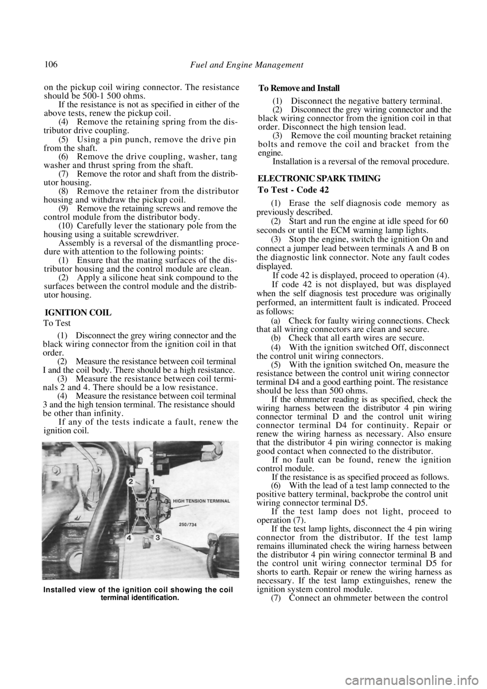
To Test
(1) Disconnect the grey wiring connector and the
black wiring connector from the ignition coil in that
order. (2) Measure the resistance between coil terminal
I and the coil body. There should be a high resistance. (3) Measure the resistance between coil termi-
nals 2 and 4. There should be a low resistance. (4) Measure the resistance between coil terminal
3 and the high tension termin al. The resistance should
be other than infinity.
If any of the tests indicate a fault, renew the
ignition coil.
To Remove and Install
(1) Disconnect the negative battery terminal.
(2) Disconnect the grey wiring connector and the
black wiring connector from the ignition coil in that
order. Disconnect the high tension lead. (3) Remove the coil mounting bracket retaining
bolts and remove the coil and bracket from the
engine. Installation is a reversal of the removal procedure.
ELECTRONIC SPARK TIMING
To Test - Code 42
(1) Erase the self diagnosis code memory as
previously described. (2) Start and run the engine at idle speed for 60
seconds or until the ECM warning lamp lights.
(3) Stop the engine, switch the ignition On and
connect a jumper lead between terminals A and B on
the diagnostic link connector . Note any fault codes
displayed. If code 42 is displayed, proceed to operation (4).
If code 42 is not displayed, but was displayed
when the self diagnosis test procedure was originally
performed, an intermittent fault is indicated. Proceed
as follows:
(a) Check for faulty wiri ng connections. Check
that all wiring connectors are clean and secure.
(b) Check that all earth wires are secure.
(4) With the ignition switched Off, disconnect
the control unit wiring connectors. (5) With the ignition switched On, measure the
resistance between the contro l unit wiring connector
terminal D4 and a good earthing point. The resistance
should be less than 500 ohms.
If the ohmmeter reading is as specified, check the
wiring harness between the distributor 4 pin wiring
connector terminal D and the control unit wiring
connector terminal D4 for continuity. Repair or
renew the wiring harness as necessary. Also ensure
that the distributor 4 pin wiring connector is making
good contact when connected to the distributor.
If no fault can be found, renew the ignition
control module.
If the resistance is as specified proceed as follows.
(6) With the lead of a test lamp connected to the
positive battery terminal, backprobe the control unit
wiring connector terminal D5.
If the test lamp does not light, proceed to
operation (7).
If the test lamp lights, disconnect the 4 pin wiring
connector from the distributor. If the test lamp
remains illuminated check the wiring harness between
the distributor 4 pin wiring connector terminal B and
the control unit wiring connector terminal D5 for
shorts to earth. Repair or renew the wiring harness as
necessary. If the test lamp extinguishes, renew the
ignition system control module.
(7) Connect an ohmmeter between the control
Installed view of the ignition coil showing the coil
terminal identification.
Page 109 of 238
Fuel and Engine Management 109
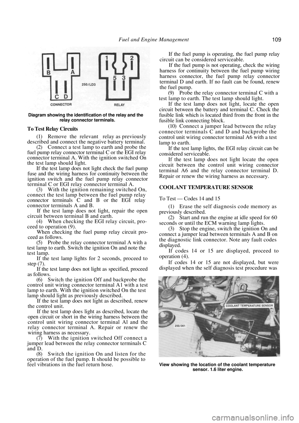
Diagram showing the identification of the relay and the relay connector terminals.
To Test Relay Circuits
(1) Remove the relevant relay as previously
described and connect the ne gative battery terminal.
(2) Connect a test lamp to earth and probe the
fuel pump relay connector terminal C or the EGI relay
connector terminal A. With the ignition switched On
the test lamp should light. If the test lamp does not light check the fuel pump
fuse and the wiring harness for continuity between the
ignition switch and the fuel pump relay connector
terminal C or EGI rela y connector terminal A.
(3) With the ignition remaining switched On,
connect the test lamp between the fuel pump relay
connector terminals C and B or the EGI relay
connector terminals A and B.
If the test lamp does not light, repair the open
circuit between terminal B and earth.
(4) When checking the EGI relay circuit, pro-
ceed to operation (9).
When checking the fuel pu mp relay circuit pro-
ceed as follows.
(5) Probe the relay connector terminal A with a
test lamp to earth. Switch the ignition On and note the
test lamp.
If the test lamp lights for 2 seconds, proceed to
step (7).
If the test lamp does not light as specified, proceed
as follows.
(6) Switch the ignition Off and backprobe the
control unit wiring connector terminal A1 with a test
lamp to earth. With the ignition switched On the test
lamp should light as previously described.
If the test lamp does not light as described, renew
the control unit.
If the test lamp does light as described, locate the
open circuit or short in the wiring harness between the
control unit wiring connector terminal Al and the
relay connector terminal A. Repair or renew the
wiring harness as necessary.
(7) With the ignition switched Off connect a
jumper lead between the relay connector terminals C
and D. (8) Switch the ignition On and listen for the
operation of the fuel pump. It should be possible to
feel vibrations in the fuel return hose. If the fuel pump is operating, the fuel pump relay
circuit can be considered serviceable.
If the fuel pump is not operating, check the wiring
harness for continuity between the fuel pump wiring
harness connector, the fuel pump relay connector
terminal D and earth. If no fault can be found, renew
the fuel pump.
(9) Probe the relay connector terminal C with a
test lamp to earth. The test lamp should light.
If the test lamp does not light, locate the open
circuit between the battery and terminal C. Check the
fusible link which is located third from the front in the
fusible link connecting block.
(10) Connect a jumper lead between the relay
connector terminals C and D and backprobe the
control unit wiring connector terminal A6 with a test
lamp to earth.
If the test lamp lights, the EGI relay circuit can be
considered serviceable.
If the test lamp does not light locate the open
circuit between the contro l unit wiring connector
terminal A6 and the relay connector terminal D.
Repair or renew the wiring harness as necessary.
COOLANT TEMPERATURE SENSOR
To Test — Codes 14 and 15
(1) Erase the self diagnosis code memory as
previously described. (2) Start and run the engine at idle speed for 60
seconds or until the ECM warning lamp lights.
(3) Stop the engine, switch the ignition On and
connect a jumper lead between terminals A and B on
the diagnostic link connect or. Note any fault codes
displayed. If codes 14 or 15 are displayed, proceed to
operation (4).
If codes 14 or 15 are not displayed, but were
displayed when the self diagnosis test procedure was
View showing the location of the coolant temperature
sensor. 1.6 liter engine.
Page 110 of 238

110 Fuel and Engine Management
originally performed, an intermittent fault is indi-
cated. Proceed as follows:
(a) Check for faulty wiri ng connections. Check
that all wiring connectors are clean and secure. (b) Check that all earth wires are secure.
(4) Disconnect the wiring connector from the
coolant temperature sensor. (5) With the ignition switched On, measure the
voltage across the terminals on the coolant tempera-
ture sensor wiring connector. The voltage should be
4-6 volts.
If the voltage is below 4 volts, proceed to opera-
tion (9).
If the voltage is as specified, proceed as follows.
(6) Remove the coolant temperature sensor
from the vehicle. (7) Connect an ohmmeter to the coolant temper-
ature sensor terminals. (8) Immerse the meta1 end of the coolant
tem-
perature sensor in a 50/50 mixture of glycol and iced
water at a temperature of 0 deg C. The resistance
should be 6 000 ohms. Slowly heat the mixture and measure the resis-
tance of the coolant temperature sensor at the follow-
ing temperatures. Compare the results with the spec-
ified values:
0 d e g C ................................................. 6 000 ohms
20 deg C .................................................. 2 500 ohms
30 deg C .................................................. 1 800 ohms
40 deg C.................................................. 1 200 ohms
70 deg C .......................................................450 ohms
90 degC .......................................................250 ohms
100 deg C.....................................................190 ohms
110 deg C.....................................................110 ohms
If the resistances obtained are not as specified at
any of the given temperatures, renew the coolant
temperature sensor and retest for fault codes.
(9) Disconnect the control unit wiring connec-
tors.
(10) Check the wiring harness for shorts and
continuity between the coolant temperature sensor
wiring connector terminals and the control unit wiring
connector terminals C10 and D2. Repair or renew the
wiring harness as necessary.
Also check the control unit terminals for damage.
If no fault is found, renew the control unit and
retest for fault codes.
To Remove and Install
(1) Disconnect the negative battery terminal.
(2) Disconnect the wiring connector from the
coolant temperature sensor.
(3) Drain the coolant as described in the Cooling
and Heating Systems section to a level below the
sensor.
(4) Unscrew the sensor from the thermostat
housing. Installation is a reversal of the removal procedure
with attention to the following points;
(1) Apply Loctite 675 or a similar conductive
sealer to the threads of th e sensor. Tighten the sensor
to the specified torque.
(2) Fill the cooling system with the correct
mixture of water and inhibitor as described in the
Cooling and Heating Systems section. (3) Ensure that the wiring connector is clean and
secure.
THROTTLE POSITION SENSOR
To Test - Codes 21 and 22
NOTE: The following test procedure as-
sumes that fault codes 21 or 22 have been
displayed during the se lf diagnosis test pro-
cedure. If no codes have been displayed but
the operation of the throttle position sensor
is suspect, begin the test procedure at oper-
ation (24).
(1) Erase the self diagnosis code memory as
previously described.
(2) Start and run the engine at idle speed for 60
seconds or until the ECM warning lamp lights. If the engine will not start, disconnect the throttle
position sensor wiring co nnector and proceed to
operation (8). .
(3) With the engine id ling, quickly increase the
engine speed to 3 000 rpm and return to idle.
If the ECM warning lamp remains illuminated,
proceed to operation (4).
If the ECM warning lamp extinguishes, an inter-
mittent fault is indicated. Proceed as follows:
(a) Check for faulty wiri ng connections. Check
that all wiring connectors are clean and secure. (b) Check that all earth wires are secure.
(4) Stop the engine, switch the ignition On and
connect a jumper lead between terminals A and B on
the diagnostic link connect or. Note any fault codes
displayed.
If codes 21 or 22 are displayed, proceed as
follows.
(5) Remove the jumper lead from the diagnostic
link connector. (6) Erase the self diagnosis codes as previously
described. (7) Disconnect the wiring connector from the
throttle position sensor. If code 22 was displayed in operation (4), proceed
to operation (13).
If code 21 was displayed in operation (4), proceed
as follows.
(8) Start and run the engine at idle speed for 2
minutes or until the ECM warning lamp lights. If the
engine will not start, pr oceed to operation (11).
(9) Stop the engine, switch the ignition On and
connect a jumper lead between terminals A and B on
Page 111 of 238
Fuel and Engine Management 111
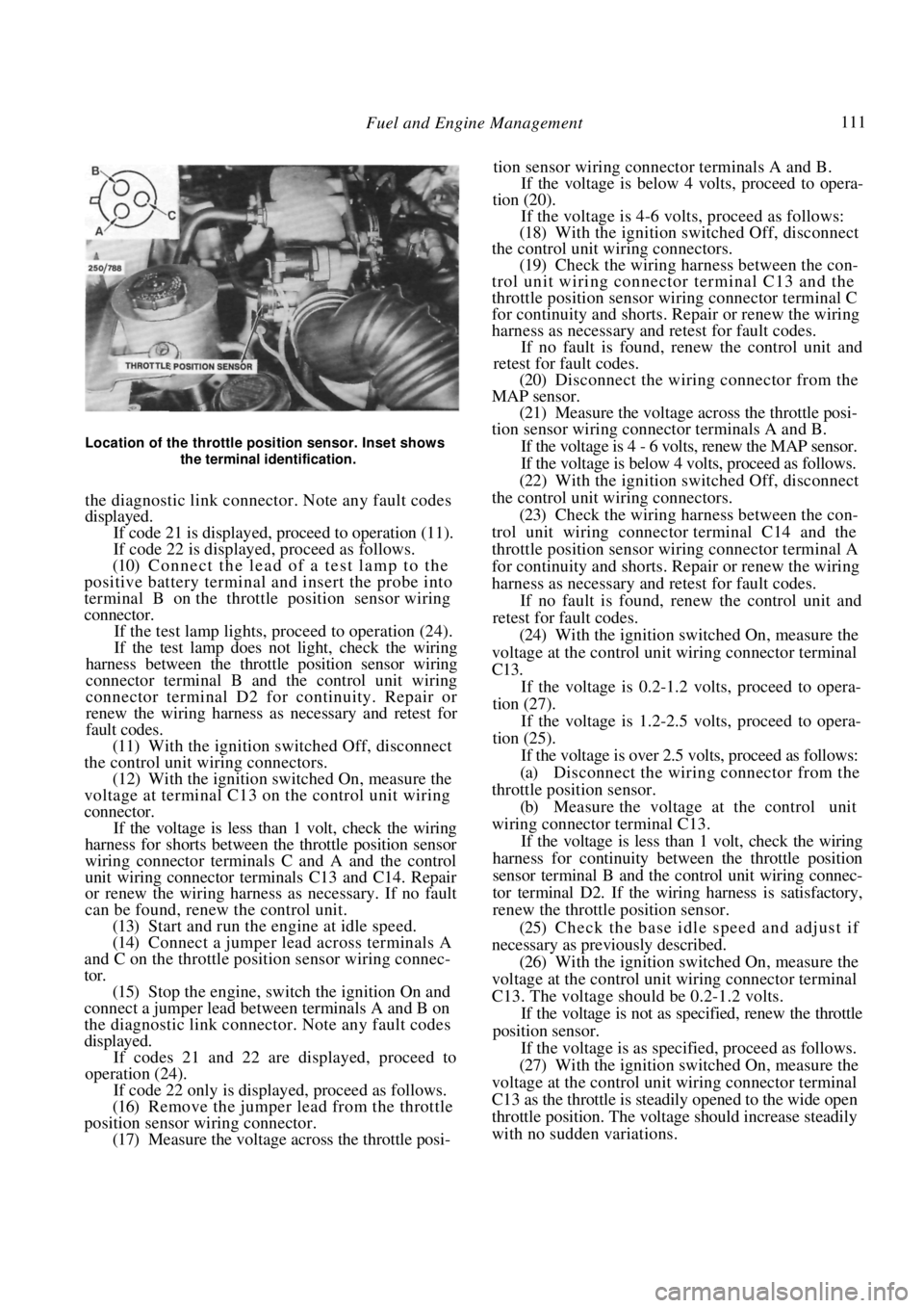
Location of the throttle position sensor. Inset shows the terminal identification.
the diagnostic link connector. Note any fault codes
displayed.
If code 21 is displayed, proceed to operation (11).
If code 22 is displayed, proceed as follows.
(10) Connect the lead of a test lamp to the
positive battery terminal and insert the probe into
terminal B on the throttle position sensor wiring
connector.
If the test lamp lights, pr oceed to operation (24).
If the test lamp does not light, check the wiring
harness between the throt tle position sensor wiring
connector terminal B and the control unit wiring
connector terminal D2 fo r continuity. Repair or
renew the wiring harness as necessary and retest for
fault codes.
(11) With the ignition switched Off, disconnect
the control unit wiring connectors. (12) With the ignition switched On, measure the
voltage at terminal C13 on the control unit wiring
connector.
If the voltage is less than 1 volt, check the wiring
harness for shorts between the throttle position sensor
wiring connector terminals C and A and the control
unit wiring connector terminals C13 and C14. Repair
or renew the wiring harness as necessary. If no fault
can be found, renew the control unit.
(13) Start and run the engine at idle speed.
(14) Connect a jumper lead across terminals A
and C on the throttle position sensor wiring connec-
tor. (15) Stop the engine, switch the ignition On and
connect a jumper lead between terminals A and B on
the diagnostic link connector . Note any fault codes
displayed. If codes 21 and 22 are displayed, proceed to
operation (24).
If code 22 only is displayed, proceed as follows.
(16) Remove the jumper lead from the throttle
position sensor wiring connector. (17) Measure the voltage across the throttle posi- tion sensor wiring connector terminals A and B.
If the voltage is below 4 volts, proceed to opera-
tion (20).
If the voltage is 4-6 volts, proceed as follows:
(18) With the ignition switched Off, disconnect
the control unit wiring connectors.
(19) Check the wiring harness between the con-
trol unit wiring connector terminal C13 and the
throttle position sensor wiring connector terminal C
for continuity and shorts. Repair or renew the wiring
harness as necessary and retest for fault codes. If no fault is found, renew the control unit and
retest for fault codes.
(20) Disconnect the wiring connector from the
MAP sensor. (21) Measure the voltage across the throttle posi-
tion sensor wiring connector terminals A and B.
If the voltage is 4 - 6 volts, renew the MAP sensor.
If the voltage is below 4 volts, proceed as follows.
(22) With the ignition switched Off, disconnect
the control unit wiring connectors. (23) Check the wiring harness between the con-
trol unit wiring connecto r terminal C14 and the
throttle position sensor wiring connector terminal A
for continuity and shorts. Repair or renew the wiring
harness as necessary and retest for fault codes. If no fault is found, renew the control unit and
retest for fault codes.
(24) With the ignition switched On, measure the
voltage at the control unit wiring connector terminal
C13.
If the voltage is 0.2-1.2 volts, proceed to opera-
tion (27).
If the voltage is 1.2-2.5 volts, proceed to opera-
tion (25).
If the voltage is over 2.5 volts, proceed as follows:
(a) Disconnect the wiring connector from the
throttle position sensor. (b) Measure the voltage at the control unit
wiring connector terminal C13. If the voltage is less than 1 volt, check the wiring
harness for continuity between the throttle position
sensor terminal B and the control unit wiring connec-
tor terminal D2. If the wiring harness is satisfactory,
renew the throttle position sensor.
(25) Check the base idle sp eed and adjust if
necessary as previously described. (26) With the ignition switched On, measure the
voltage at the control unit wiring connector terminal
C13. The voltage should be 0.2-1.2 volts. If the voltage is not as specified, renew the throttle
position sensor.
If the voltage is as specified, proceed as follows.
(27) With the ignition switched On, measure the
voltage at the control unit wiring connector terminal
C13 as the throttle is steadily opened to the wide open
throttle position. The voltage should increase steadily
with no sudden variations.
Page 112 of 238
112 Fuel and Engine Management
If the voltage does not increase as specified, renew
the throttle position sensor.
If the voltage is as specified, proceed as follows.
(28) With the ignition switched On and the
throttle valve held fully open, measure the voltage at
control unit wiring connector terminal C13. The
voltage should be above 4 volts.
If the voltage is below 4 volts, renew the throttle
position sensor.
To Remove and Install
(1) Disconnect the negative battery terminal.
(2) On 1.6 liter engines, remove the air cleaner
assembly as previously described. (3) Disconnect the throttle position sensor wir-
ing connector. (4) Remove the throttle position sensor retain-
ing screws and remove the throttle position sensor
from the throttle body. Installation is a reversal of the removal procedure
with attention to the following points:
(1) Ensure that the throttle valve is in the fully
closed position. (2) Tighten the retaining screws securely and
install the wiring connector.
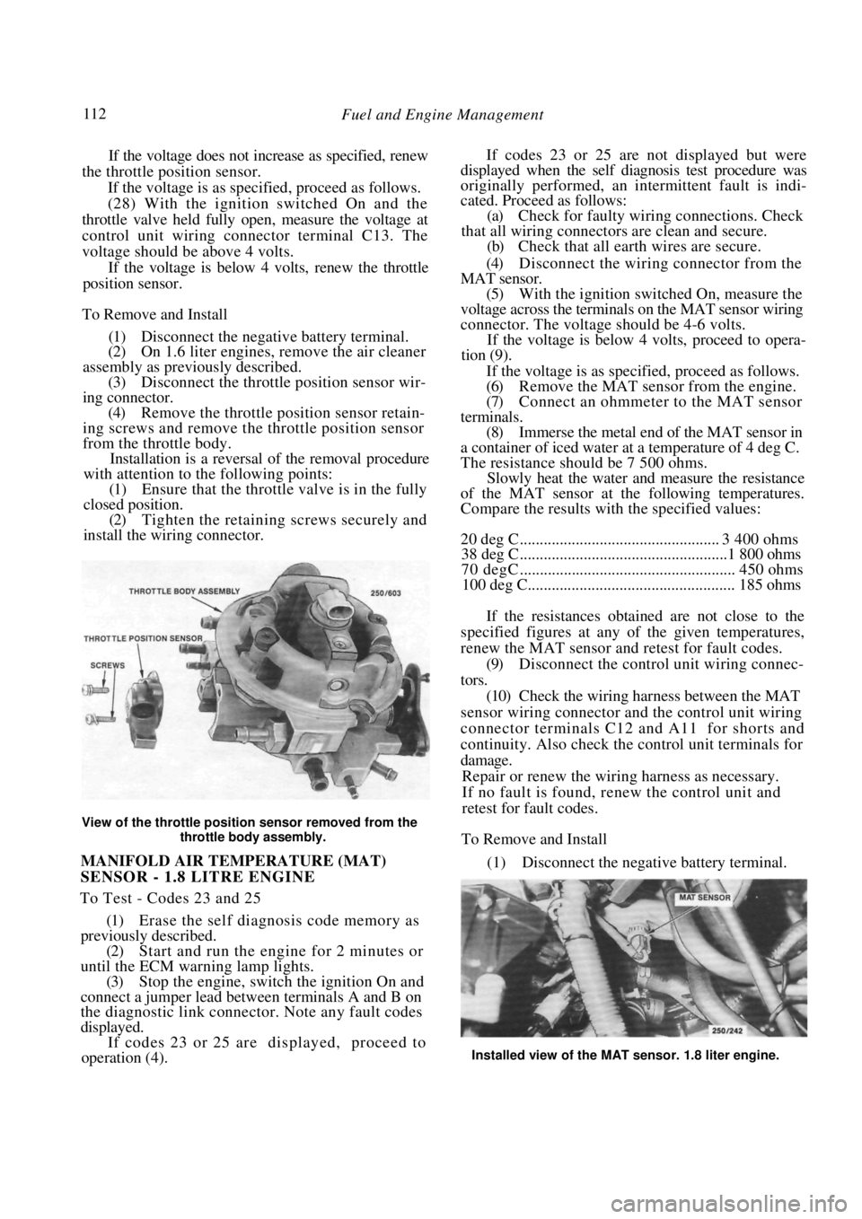
View of the throttle positi on sensor removed from the
throttle body assembly.
MANIFOLD AIR TEMPERATURE (MAT)
SENSOR - 1.8 LITRE ENGINE
To Test - Codes 23 and 25
(1) Erase the self diagnosis code memory as
previously described.
(2) Start and run the engine for 2 minutes or
until the ECM warning lamp lights. (3) Stop the engine, switch the ignition On and
connect a jumper lead between terminals A and B on
the diagnostic link connector . Note any fault codes
displayed. If codes 23 or 25 are displayed, proceed to
operation (4).
If codes 23 or 25 are not displayed but were
displayed when the self diagnosis test procedure was
originally performed, an intermittent fault is indi-
cated. Proceed as follows:
(a) Check for faulty wiri ng connections. Check
that all wiring connectors are clean and secure. (b) Check that all earth wires are secure.
(4) Disconnect the wiring connector from the
MAT sensor. (5) With the ignition switched On, measure the
voltage across the terminals on the MAT sensor wiring
connector. The voltage s hould be 4-6 volts.
If the voltage is below 4 volts, proceed to opera-
tion (9).
If the voltage is as specified, proceed as follows.
(6) Remove the MAT sensor from the engine.
(7) Connect an ohmmeter to the MAT sensor
terminals. (8) Immerse the metal end of the MAT sensor in
a container of iced water at a temperature of 4 deg C.
The resistance should be 7 500 ohms. Slowly heat the water and measure the resistance
of the MAT sensor at the following temperatures.
Compare the results with the specified values:
20 deg C .................................................. 3 400 ohms
38 deg C....................................................1 800 ohms
70 degC ...................................................... 450 ohms
100 deg C.................................................... 185 ohms
If the resistances obtained are not close to the
specified figures at any of the given temperatures,
renew the MAT sensor and retest for fault codes.
(9) Disconnect the control unit wiring connec-
tors. (10) Check the wiring harness between the MAT
sensor wiring connector and the control unit wiring
connector terminals C12 and A11 for shorts and
continuity. Also check the control unit terminals for
damage. Repair or renew the wiring harness as necessary.
If no fault is found, renew the control unit and
retest for fault codes.
To Remove and Install
(1) Disconnect the negative battery terminal.
Installed view of the MAT sensor. 1.8 liter engine.