service schedule NISSAN PULSAR 1987 Workshop Manual
[x] Cancel search | Manufacturer: NISSAN, Model Year: 1987, Model line: PULSAR, Model: NISSAN PULSAR 1987Pages: 238, PDF Size: 28.91 MB
Page 3 of 238

CONTENTS
INTRODUCTION........................................ 5
VEHICLE IDENTIFICATION AND
GENERAL SPECIFICATIONS................. 7
GENERAL INFORMATION...................... 8
Tools and equipment ............................................. 8 Safety .................................................................... 10
General repair procedures..................................... 11
LUBRICATION AND MAINTENANCE... 14
Specifications......................................................... 14
How to grease and oil change .............................. 14
Service schedule ................................................... 17
WHEELS AND TYRES............................. 21
Specifications......................................................... 21
How to change a road wheel ................................ 21
Tire wear troubl e shooting ..................................... 22
Care and main tenance ......................................... 23
ENGINE TUNE-UP.................................... 25
Tune-up specifications ........................................... 25
Tune-up operat ions............................................... 25
ROADSIDE TROUBLE SHOOTING....... 32
Trouble shoot ing.................................................... 32
To check ignition and el ectrical system ................ 33
To check fuel system ............................................ 34
To check mechani cal system ................................ 35
ENGINE....................................................... 37
Specifications ........................................................ 37
Engine mechanical tr ouble shooting ...................... 39
Description ............................................................ 41
Engine and transaxle assembly ........................... 42
Manifolds ............................................................... 44 Camshaft, rocker arms and tappets..................... 48
Cylinder head........................................................ 50
Engine sump and oil pum p pickup pipe................ 54
Oil pump ............................................................... 55
Pistons, connecting rods and cylinder bores ........ 57
Crankshaft and bearings ...................................... 60
Flywheel /drive plate............................................... 63
Engine mountings.................................................. 64
Exhaust system .................................................... 66
COOLING AND HEATING SYSTEMS.... 68
Specifications ........................................................ 68 Cooling system trouble shooting ........................... 68
Heater and air conditioner trouble shooting ......... 69 Description ............................................................ 70
Radiator ................................................................ 70
Cooling fan ............................................................ 73
Thermost at............................................................ 75
Thermostat housing .............................................. 76
Water pump .......................................................... 76
Welch plugs .......................................................... 76
Heater unit, water valv e and controls ................... 77
Blower fan ............................................................. 80
Air condition ing ..................................................... 80
FUEL AND ENGINE MANAGEMENT ... 82
Specifications ........................................................ 82 Fuel and engine management trouble shooting ... 82
Description ............................................................ 84
Service precautions and procedures
..................... 86
System diagnosis and adjustments ...................... 89
Fuel supply components ....................................... 92
Air flow components .............................................. 98
Electronic components .......................................... 104
EMISSION CONTROL............................. 117
Introduction ........................................................... 117
Crankcase ventilati on system............................... 117
Evaporate control system..................................... 117
Air preheat system — 1.6 liter engines ................ 119
Exhaust control system ........................................ 120
CLUTCH...................................................... 121
Specifications........................................................ 121
Clutch trouble shooting......................................... 121
Description ............................................................ 122
Clutch unit and release mechanism..................... 123
Clutch pedal ......................................................... 124
Clutch c able.......................................................... 124
Clutch adjustments ............................................... 125
MANUAL TRANSAXLE AND
DRIVE SHAFTS......................................... 126
Specifications ........................................................ 126
Manual transaxle and drive shaft trouble shooting 126
Description............................................................ 128
Transaxle assembly.............................................. 129
Differential and final drive assembly ..................... 135
Gear lever assembly ............................................ 136
Drive shafts .......................................................... 137
AUTOMATIC TRANSAXLE....................... 140
Specifications........................................................ 140
Automatic transaxle trouble shooting.................... 140
Description............................................................ 141
Transaxle fluid ...................................................... 141
Brake band........................................................... 142
Kickdown cable .................................................... 142
Transaxle select or linkage ................................... 142
Neutral safety switch ............................................ 142
Transaxle assembly .............................................. 143
STEERING................................................. 145
PART 1. STEERING TROUBLE SHOOTING....145
Faults, causes and remedies................................ 145
PART 2. MANUA L STEERING......................... 147
Specifications ........................................................ 147
Description............................................................ 147
Steering wheel ...................................................... 147
Steering column.................................................... 148
Steering gear assembly ....................................... 149
PART 3. POWE R STEERING .......................... 152
Specifications........................................................ 152
Description............................................................ 152
In car adjustments, checks and minor repairs ..... 152
Steering wheel ...................................................... 153
Steering column.................................................... 153 Power steering pump ........................................... 153
Power steering gear assembly............................. 154
Page 16 of 238

16 Lubrication and Maintenance
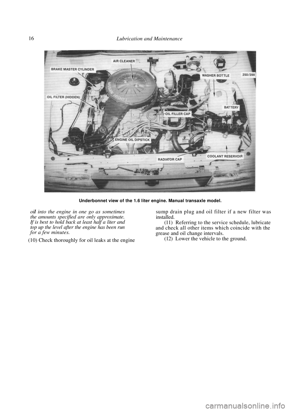
Underbonnet view of the 1.6 liter engine. Manual transaxle model.
oil into the engine in one go as sometimes
the amounts specified are only approximate.
If is best to hold back at least half a liter and
top up the level after the engine has been run
for a few minutes.
(10) Check thoroughly for oil leaks at the engine
sump drain plug and oil filter if a new filter was
installed.
(11) Referring to the service schedule, lubricate
and check all other items which coincide with the
grease and oil change intervals.
(12) Lower the vehicle to the ground.
Page 17 of 238

Lubrication and Maintenance 17
2. SERVICE SCHEDULE
This Section Removed
Page 195 of 238

Electrical System 195
(2) Remove the battery holding clamp and lift
the battery from the vehicle.
Installation is a reversal of the removal procedure
with attention to the following points:
Ensure that the terminals and posts are
clean. When connecting the l eads to the battery,
ensure that the polarity is correct. Connect the
positive lead first. Do not over tighten the terminal clamp
nuts.
Apply petroleum jelly to the battery termi-
nals to prevent corrosion.
MAINTENANCE
Battery maintenance should be performed at the
scheduled services.
NOTE: Keep naked flames away from the
battery as the battery gases are highly
explosive.
(1) Keep the battery and the surrounding area
clean and dry. In particular, ensure that the top of the
battery is free from dirt and moisture to prevent a
voltage drop between the terminals.
If necessary, clean the battery case as follows:
Remove the battery from the vehicle as
previously described.
Pour hot water over the battery being careful
not to allow any water to enter the battery through the
filler cap vent holes. Wipe the battery case clean.
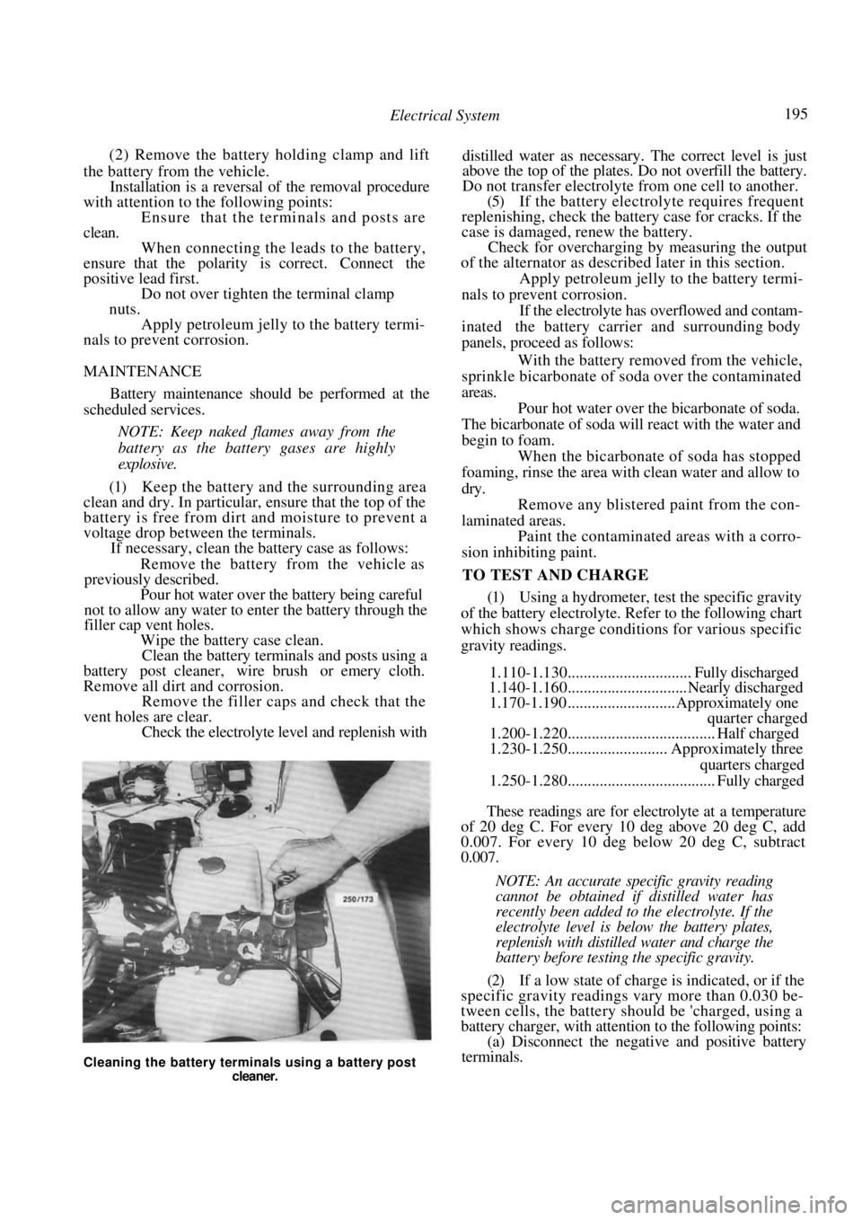
Clean the battery terminals and posts using a
battery post cleaner, wire brush or emery cloth.
Remove all dirt and corrosion.
Remove the filler caps and check that the
vent holes are clear. Check the electrolyte le vel and replenish with distilled water as necessary. The correct level is just
above the top of the plates. Do not overfill the battery.
Do not transfer electrolyte from one cell to another.
(5) If the battery electrolyte requires frequent
replenishing, check the batt ery case for cracks. If the
case is damaged, renew the battery.
Check for overcharging by measuring the output
of the alternator as described later in this section.
Apply petroleum jelly to the battery termi-
nals to prevent corrosion. If the electrolyte has overflowed and contam-
inated the battery carrier and surrounding body
panels, proceed as follows:
With the battery removed from the vehicle,
sprinkle bicarbonate of soda over the contaminated
areas.
Pour hot water over the bicarbonate of soda.
The bicarbonate of soda will react with the water and
begin to foam. When the bicarbonate of soda has stopped
foaming, rinse the area with clean water and allow to
dry. Remove any blistered paint from the con-
laminated areas. Paint the contaminated areas with a corro-
sion inhibiting paint.
TO TEST AND CHARGE
(1) Using a hydrometer, test the specific gravity
of the battery electrolyte. Refer to the following chart
which shows charge conditi ons for various specific
gravity readings.
1.110-1.130............................... Fully discharged
1.140-1.160..............................Nearly discharged
1.170-1.190 ........................... Approximately one
quarter charged
1.200-1.220..................................... Half charged
1.230-1.250......................... Approximately three
quarters charged
1.250-1.280..................................... Fully charged
These readings are for electrolyte at a temperature
of 20 deg C. For every 10 deg above 20 deg C, add
0.007. For every 10 deg below 20 deg C, subtract
0.007.
NOTE: An accurate specific gravity reading
cannot be obtained if distilled water has
recently been added to the electrolyte. If the
electrolyte level is below the battery plates,
replenish with distilled water and charge the
battery before testing the specific gravity.
(2) If a low state of charge is indicated, or if the
specific gravity readings vary more than 0.030 be-
tween cells, the battery s hould be 'charged, using a
battery charger, with attention to the following points:
(a) Disconnect the negati ve and positive battery
terminals.
Cleaning the battery terminals using a battery post
cleaner.