headlamp NISSAN PULSAR 1987 Workshop Manual
[x] Cancel search | Manufacturer: NISSAN, Model Year: 1987, Model line: PULSAR, Model: NISSAN PULSAR 1987Pages: 238, PDF Size: 28.91 MB
Page 33 of 238
Roadside Trouble Shooting
(5) Place the vent caps loosely over the cell
apertures.
(6) Connect one end of the red jumper lead to
the positive ( + ) battery terminal of the booster
battery and the other end of the red lead to the
positive (+) battery terminal of the discharged bat-
tery.
NOTE: The battery emits hydrogen gas
which is explosive. Do not expose the battery
to naked /lames or sparks.
Do not lean over the battery when con-
necting the jumper leads.
Do not allow the ends of the jumper leads
to touch one another or any part of the
engine.
(7) Connect one end of the black juniper lead to
the negative (-) battery terminal of the booster
battery and the other end of the black lead to a good
earthing point on the engine of the vehicle with the
discharged battery.
NOTE: Do not connect the jumper lead
directly to the negative (-) battery terminal
of the discharged battery.
(8) Start the engine on the vehicle with the
booster battery and run the engine at a moderate
speed. (9) Start the engine on the vehicle with the
discharged battery.
(10) If possible, leave the engines of both vehi-
cles running for 10 minutes.
(11) Disconnect the jumper leads in the reverse
order of the sequence in which they were connected.
2. TO CHECK IGNITION AND ELECTRICAL SYSTEM
(1) Switch on the ignition and check for warning
lamp illumination on the dashboard. (2) Operate the starter and check that the starter
rotates the engine at a steady speed.
(3) Switch on the headlamps and check for good
light intensity. Should the lamps not illum inate or the starter
motor not turn the engine, carry out the following
steps:
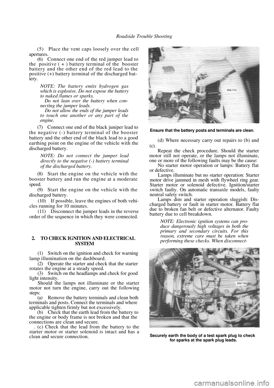
(a) Remove the battery terminals and clean both
terminals and posts. Connect the terminals and where
applicable tighten firmly but not excessively.
(b) Check that the earth lead from the battery to
the engine or body frame is not broken and that the
connections are clean and secure. . (c) Check that the lead from the battery to the
starter motor or starter solenoid is intact and has a
clean and secure connection.
Ensure that the battery posts and terminals are clean.
(d) Where necessary carry out repairs to (b) and
(c).
Repeat the check procedur e. Should the starter
motor still not operate, or the lamps not illuminate,
one or more of the following faults may be the cause:
No starter motor operation or lamps: Battery flat
or defective.
Lamps illuminate but no starter operation: Starter
motor drive jammed in mesh with flywheel ring gear.
Starter motor or solenoid defective. Ignition/starter
switch faulty. On automatic transaxle models, faulty
neutral safety switch.
Lamps dim and starter operation sluggish: Dis-
charged battery or fault in starter motor. Battery flat
due to broken fan belt or de fective alternator. Faulty
battery due to cell breakdown.
NOTE: Electronic ignition systems can pro-
duce dangerously high voltages in both the
primary and secondary circuits. For this
reason, extreme care must be taken when
performing these checks. When disconnect-
Securely earth the body of a test spark plug to check
for sparks at the spark plug leads.
Page 192 of 238
192 Electrical System
transaxle models, check for a faulty or incorrectly
adjusted neutral safety switch.
1. Discharged battery: Check for a fault or short
circuit in the system. 2. Battery fully charged but will not crank
engine. Check for a locked drive and ring gear,
internal starter faul t or seized engine.
3. Fusible link blown: Check and repair the
cause and renew as necessary.
NOTE: Rotate the engine by hand to ensure
that the starter drive is not locked with the
flywheel ring gear and t hat the engine is not
seized. Ensure that the ignition key is
turned off before rotating the engine.
3. LIGHTING SYSTEM TROUBLE SHOOTING
LAMP OR LAMPS FAIL TO LIGHT
1. Faulty bulb(s): Check and renew the faulty
bulb(s). 2. Open circuit in the wiring or connections:
Check the lamp circuits and rectify as necessary.
1. Faulty lamp switch: Check and if necessary
renew the lamp switch. 2. Faulty fuse or fuse connection: Repair the
fuse connection or renew the fuse. 3. Lamp relay faulty: Check and renew as
necessary.
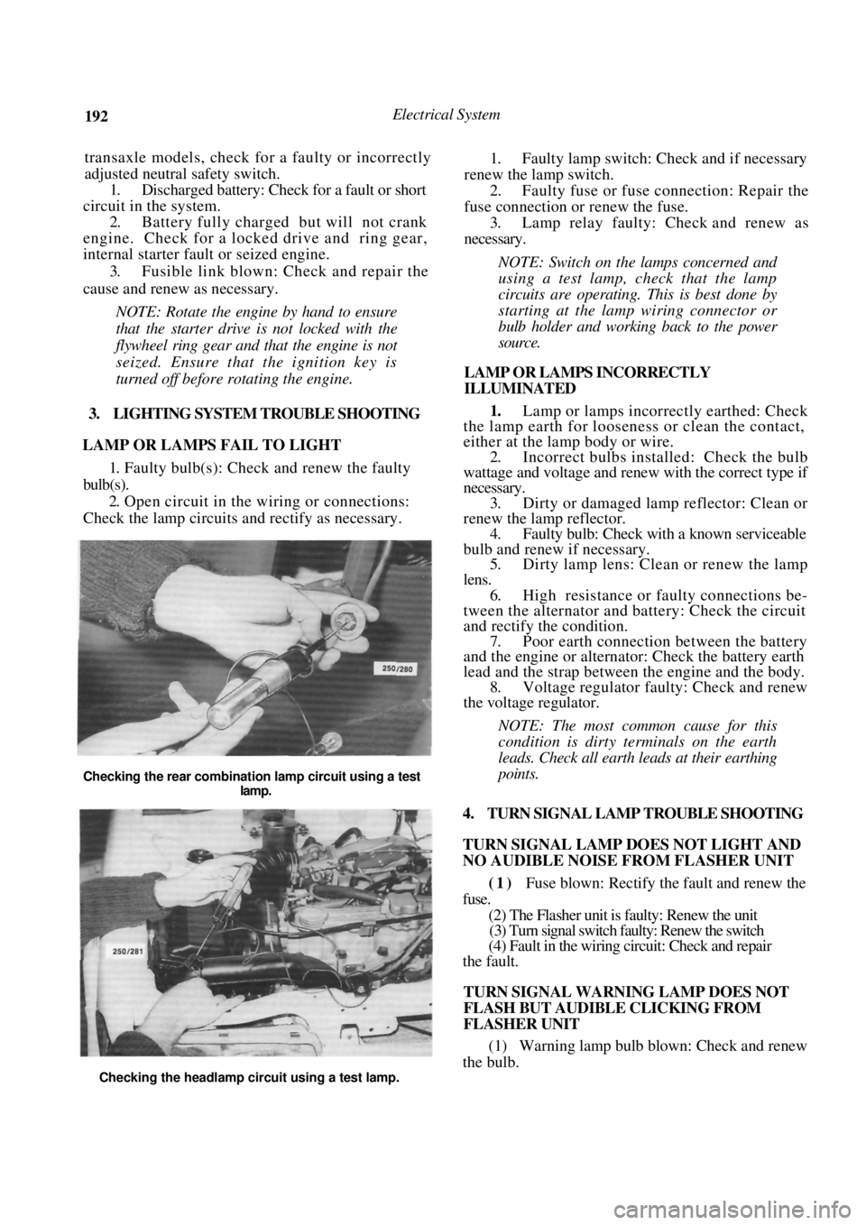
NOTE: Switch on the lamps concerned and
using a test lamp, check that the lamp
circuits are operating. This is best done by
starting at the lamp wiring connector or
bulb holder and work ing back to the power
source.
LAMP OR LAMPS INCORRECTLY
ILLUMINATED
1. Lamp or lamps incorrectly earthed: Check
the lamp earth for loosene ss or clean the contact,
either at the lamp body or wire.
2. Incorrect bulbs installe d: Check the bulb
wattage and voltage and renew with the correct type if
necessary. 3. Dirty or damaged lamp reflector: Clean or
renew the lamp reflector. 4. Faulty bulb: Check with a known serviceable
bulb and renew if necessary. 5. Dirty lamp lens: Clean or renew the lamp
lens. 6. High resistance or faulty connections be-
tween the alternator and battery: Check the circuit
and rectify th e condition.
7. Poor earth connection between the battery
and the engine or alternat or: Check the battery earth
lead and the strap between the engine and the body. 8. Voltage regulator faulty: Check and renew
the voltage regulator.
NOTE: The most common cause for this
condition is dirty t erminals on the earth
leads. Check all earth leads at their earthing
points.
4. TURN SIGNAL LAMP TROUBLE SHOOTING
TURN SIGNAL LAMP DOES NOT LIGHT AND
NO AUDIBLE NOISE FROM FLASHER UNIT
(1) Fuse blown: Rectify the fault and renew the
fuse.
(2) The Flasher unit is faulty: Renew the unit
(3) Turn signal switch faulty: Renew the switch
(4) Fault in the wiring circuit: Check and repair
the fault.
TURN SIGNAL WARNING LAMP DOES NOT
FLASH BUT AUDIBLE CLICKING FROM
FLASHER UNIT
(1) Warning lamp bulb blown: Check and renew
the bulb.
Checking the rear combination lamp circuit using a test
lamp.
Checking the headlamp circuit using a test lamp.
Page 201 of 238

Electrical System 201
nosed pliers. This will safeguard the diodes
by transferring any excess heat to the jaws of
the pliers.
Using a suitable drift, install the bearing into
the drive end bracket, install the retainer plate and
screws. Tighten the screws securely. Using a suitable press and press plates, install
the bearing to the slip ring end of the rotor shaft.
Ensure that pressure is ex erted only on the inner race
and that the stop ring groove is nearest to the sl i p
rings. Ensure that the rotor sh aft rear bearing stop
ring is positioned so that the protruding part of the
ring is located in the deepest part of the groove. Install the stator, diode pack and
regulator
assembly to the slip ring e nd bracket. Install the
retaining nuts and washers and tighten securely. Install the nut and insulator to the terminal
and tighten securely. Using a piece of wire, hold the brushes in a
retracted position. Hold the drive end bracket in a soft jawed
vice and install the rotor shaft assembly to the drive
end bracket. Install the pulley, retaining nut and washer to
the rotor shaft and tighten the retaining nut to the
specified torque. Apply a heated 200 watt soldering iron to the
slip ring end bracket at the bearing mounting boss for
3-4 minutes to heat the bracket and allow the
installation of the rotor shaft rear bearing. Aligning the marks made on dismantling and
ensuring that the rotor sh aft rear bearing retaining
ring protrusion is located in the deepest part of its
groove, install the rotor/stator assembly to the slip ring
end bracket.
Remove the brush retr acting wire from the
alternator, ensure that the alternator component
marks are aligned, install the retaining through bolts
and tighten them securely. Check the alternator rotor for smooth oper-
ation and install the al ternator to the vehicle
as
previously described.
Check the alternator operation on the vehicle
as previously described.
8. STARTER MOTOR
Special Equipment Required:
To Renew Brushes — Soldering iron
To Renew Armature Bearings — Bearing puller
DESCRIPTION
Two types of starter motors are installed to the
range of vehicles covere d by this manual, either
Hitachi or Bosch.
The starter motor is the induced pole type with
four brushes and four pole shoes with field coils.
A solenoid switch is attached to the starter drive
end bracket. The solenoid plunger is connected to
the overrunning clutch and drive pinion assembly
through a lever and pivot arrangement.
When the solenoid windings are energized, the
plunger acting on the lever and pivot engages the drive
pinion with the flywheel ri ng gear and at the same
time closes the switch supplying power from the
positive lead of the battery to the starter motor field
coils and armature to operate the motor.
As the engine fires, the over-running clutch of the
drive pinion assembly prevents high speed rotation of.
and possible damage to, the starter armature if the
solenoid windings are not immediately de-energized
by releasing the ignition key.
The starter solenoid switch windings are energized
by the ignition switch.
TO TEST ON VEHICLE
Should the starter motor fail to operate when the
ignition switch is turned to the Start position, check
the following points:
Check the battery condition and state of
charge. Refer to the Battery heading for the correct
procedure.
Clean the battery terminals, taking particular
care to remove the scale from the positive ( + )
terminal post and terminal. Check the earth connection for tightness and
cleanliness.
Switch on the headlamps and turn the igni-
tion switch to Start. If the lamps dim but the starter
motor does not operate, it could indicate that a short
circuit has developed in the starting system. Check that the engine is not seized or that the
starter motor drive pinion and ring gear are not
locked as these conditions would -give the same
indications as above.
(5) If the lamps do not dim and the starter
motor does not operate, this would indicate an open
circuit such as a broken or disconnected wire or a
switch not operating.
If the vehicle is equipped with an automatic
transaxle, turn the ignition switch to Start and move
the selector lever through all the gear selection range.
If the starter motor operates in any position other
than N or P, the neutral safety switch is faulty.
(6) Check all the external wiring to ensure that
the fault is not external. If the external circuit proves
satisfactory, indicating that the problem is in the
starter motor, the unit will have to be removed and
tested.
TO REMOVE AND INSTAL
Disconnect the negative battery terminal.
Disconnect the wiring from the starter motor
solenoid. Remove the starter motor mounting bolts,
Page 206 of 238
206 Electrical System
Install the armature and yoke to the drive end
bracket rotating the drive to align the reduction gears.
Do not use force.
Install the retaining through bolts to the
commutator end bracket and lighten the through bolts
and armature end cover retaining screws securely. Install the solenoid to the drive end bracket,
install the retaining screws and tighten them securely.
Install the brush connector strap and
install
the retaining nut and washer and tighten securely.
9 . IGNITION SYSTEM
The testing and repair procedures for the ignition
system are fully covered in the Fuel and Engine
Management section.
10. STEERING WHEEL
The removal and installation procedures for the
steering wheel and horn pad are fully covered in the
Steering section.
11. SWITCHES AND CONTROLS
IGNITION SWITCH
To Remove and Install
Disconnect the negative battery terminal.
Remove the retaining screws from the steer-
ing column cover. Unclip and separate the upper and lower
steering column covers and remove the upper cover. Release the column adjusting lever and re-
move the lower cover by guiding the column adjusting
lever through the hole in the upper end of the cover.
Disconnect the ignition switch wiring at the
switch. Remove the retaining screw and withdraw
the ignition switch fr om the lock assembly.
Installation is a reversal of the removal procedure.
COMBINATION SWITCH
The combination switch is mounted at the top of
the steering column and incorporates two switches.
The parking lamp, headlamp, headlamp flasher, head-
lamp dipper and turn signal lamps are operated by a
lever on the right hand side. A lever on the left hand
side operates the windscreen washer and wiper switch.
These switches can be re newed without removing
the combination switch.
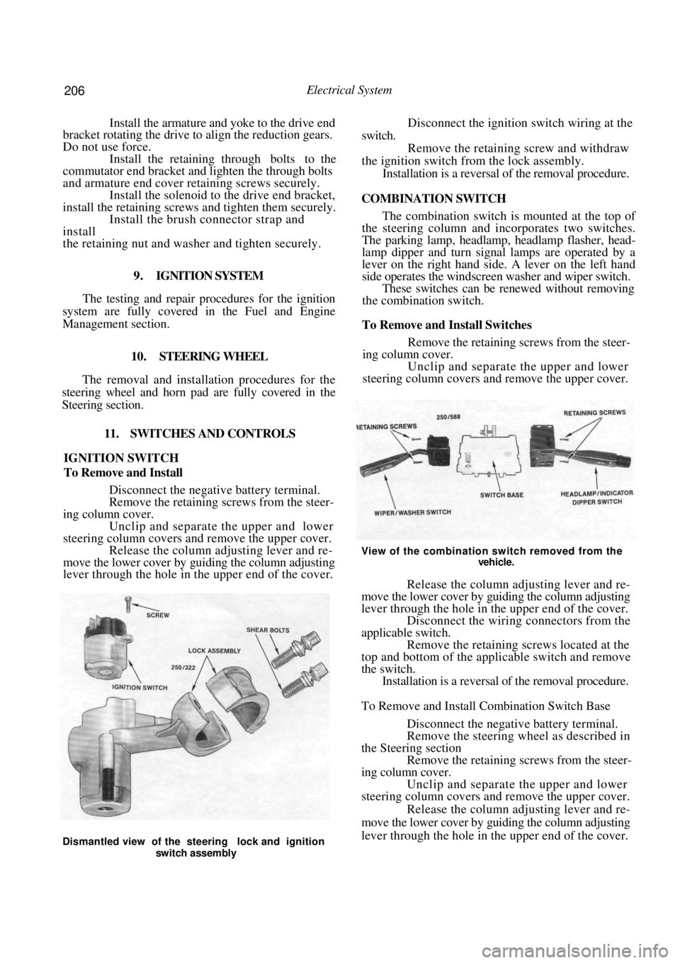
To Remove and Install Switches
Remove the retaining screws from the steer-
ing column cover.
Unclip and separate the upper and lower
steering column covers and remove the upper cover.
View of the combination switch removed from the
vehicle.
Release the column adjusting lever and re-
move the lower cover by guiding the column adjusting
lever through the hole in the upper end of the cover. Disconnect the wiring connectors from the
applicable switch. Remove the retaining screws located at the
top and bottom of the applicable switch and remove
the switch. Installation is a reversal of the removal procedure.
To Remove and Install Combination Switch Base
Disconnect the negative battery terminal.
Remove the steering wheel as described in
the Steering section Remove the retaining screws from the steer-
ing column cover. Unclip and separate the upper and lower
steering column covers and remove the upper cover.
Release the column adjusting lever and re-
move the lower cover by guiding the column adjusting
lever through the hole in the upper end of the cover.
Dismantled view of the steering lock and ignition
switch assembly
Page 210 of 238
210 Electrical System
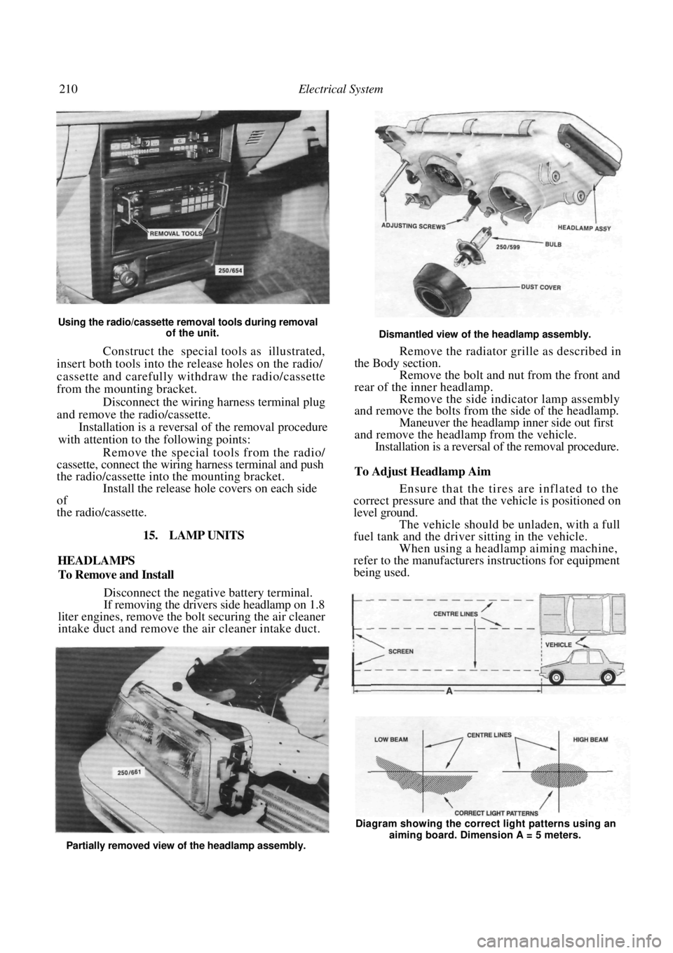
Using the radio/cassette removal tools during removal of the unit.
Construct the special tools as illustrated,
insert both tools into the release holes on the radio/
cassette and carefully withdraw the radio/cassette
from the mounting bracket.
Disconnect the wiring harness terminal plug
and remove the radio/cassette.
Installation is a reversal of the removal procedure
with attention to the following points:
Remove the special tools from the radio/
cassette, connect the wiring harness terminal and push
the radio/cassette into the mounting bracket. Install the release hole covers on each side
of
the radio/cassette.
15. LAMP UNITS
HEADLAMPS
To Remove and Install
Disconnect the negative battery terminal.
If removing the drivers side headlamp on 1.8
liter engines, remove the bo lt securing the air cleaner
intake duct and remove the air cleaner intake duct.
Dismantled view of the headlamp assembly.
Remove the radiator grille as described in
the Body section. Remove the bolt and nut from the front and
rear of the inner headlamp. Remove the side indicator lamp assembly
and remove the bolts from the side of the headlamp.
Maneuver the headlamp inner side out first
and remove the headlamp from the vehicle. Installation is a reversal of the removal procedure.
To Adjust Headlamp Aim
Ensure that the tires are inflated to the
correct pressure and that the vehicle is positioned on
level ground.
The vehicle should be unladen, with a full
fuel tank and the driver sitting in the vehicle. When using a headlamp aiming machine,
refer to the manufacturers instructions for equipment
being used.
Partially removed view of the headlamp assembly. Diagram showing the correct light patterns using an
aiming board. Dimension A = 5 meters.
Page 211 of 238
Electrical System 211
When using an aiming board, position the
vehicle five meters from and square to the aiming
board. Gently rock the vehi cle and allow the suspen-
sion to stabilize. Mark a reference line on the board to
correspond with the horizontal centre line of the
headlamp low beam bulbs. Mark two reference lines on the board to
correspond with the vertical centre lines of
the
headlamp low beam bulbs. Switch on the headlamps and select low
beam. Adjust the headlamps by turning the adjust-
ing screws located at the rear of the headlamp
assemblies. Adjust the headlamps to comply with local
regulations. As a guide, adjust the lamps so that the
low beam pattern strikes the aiming board with the
horizontal cut off point 50 mm below the headlamp
bulb horizontal centre line and the point where the
beam raises from the horizontal is on the headlamp
low beam bulb vertical centre line.
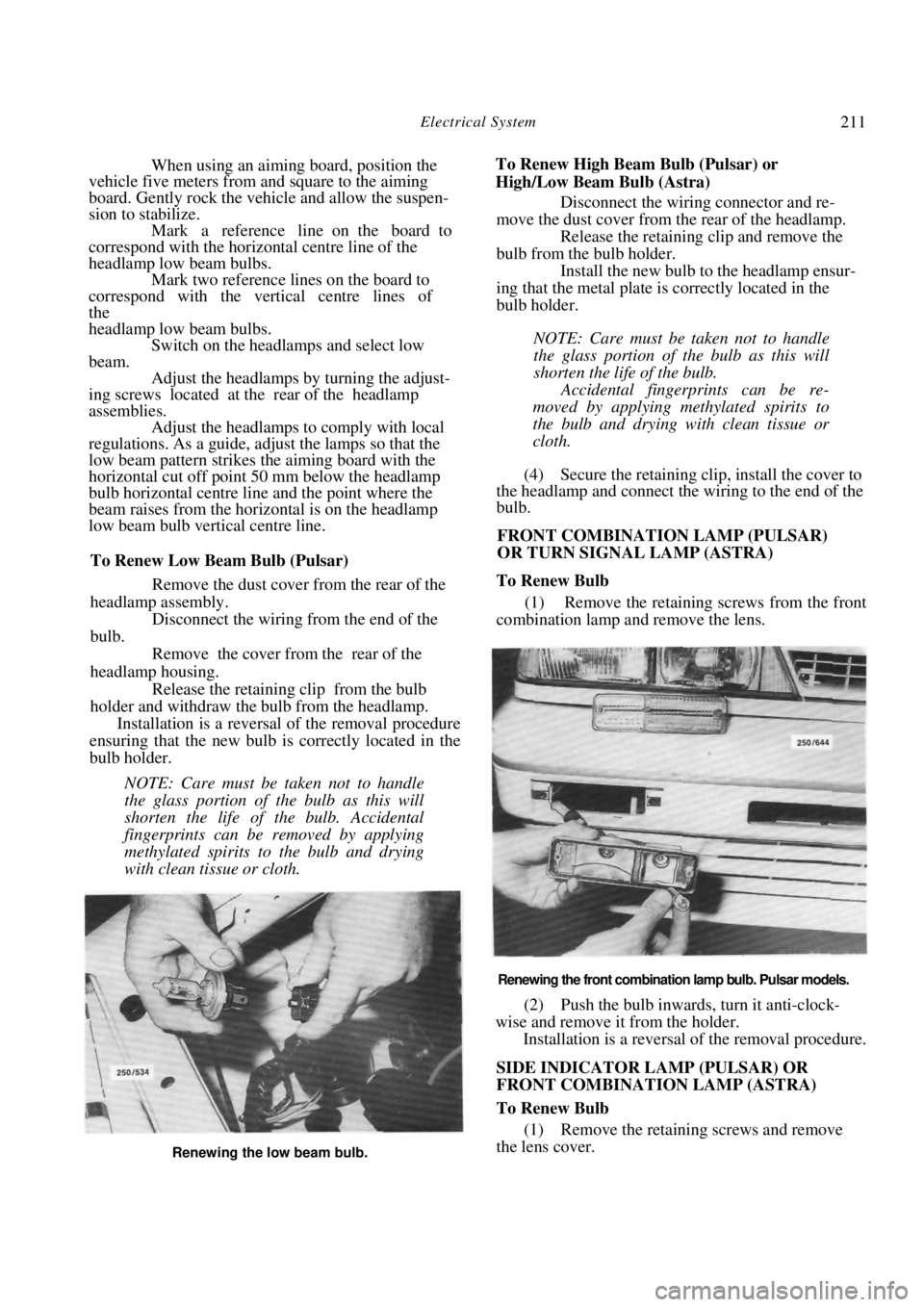
To Renew Low Beam Bulb (Pulsar)
Remove the dust cover from the rear of the
headlamp assembly.
Disconnect the wiring from the end of the
bulb.
Remove the cover from the rear of the
headlamp housing. Release the retaining clip from the bulb
holder and withdraw the bulb from the headlamp. Installation is a reversal of the removal procedure
ensuring that the new bulb is correctly located in the
bulb holder.
NOTE: Care must be taken not to handle
the glass portion of the bulb as this will
shorten the life of the bulb. Accidental
fingerprints can be removed by applying
methylated spirits to the bulb and drying
with clean tissue or cloth.
To Renew High Beam Bulb (Pulsar) or
High/Low Beam Bulb (Astra) Disconnect the wiring connector and re-
move the dust cover from the rear of the headlamp. Release the retaining clip and remove the
bulb from the bulb holder. Install the new bulb to the headlamp ensur-
ing that the metal plate is correctly located in the
bulb holder.
NOTE: Care must be taken not to handle
the glass portion of the bulb as this will
shorten the life of the bulb.
Accidental fingerprints can be re-
moved by applying methylated spirits to
the bulb and drying with clean tissue or
cloth.
(4) Secure the retaining clip, install the cover to
the headlamp and connect the wiring to the end of the
bulb.
FRONT COMBINATION LAMP (PULSAR)
OR TURN SIGNAL LAMP (ASTRA)
To Renew Bulb
(1) Remove the retaining screws from the front
combination lamp and remove the lens.
Renewing the front combination lamp bulb. Pulsar models.
(2) Push the bulb inwards, turn it anti-clock-
wise and remove it from the holder. Installation is a reversal of the removal procedure.
SIDE INDICATOR LAMP (PULSAR) OR
FRONT COMBINATION LAMP (ASTRA)
To Renew Bulb
(1) Remove the retaining screws and remove
the lens cover.
Renewing the low beam bulb.
Page 224 of 238
224 Electrical System
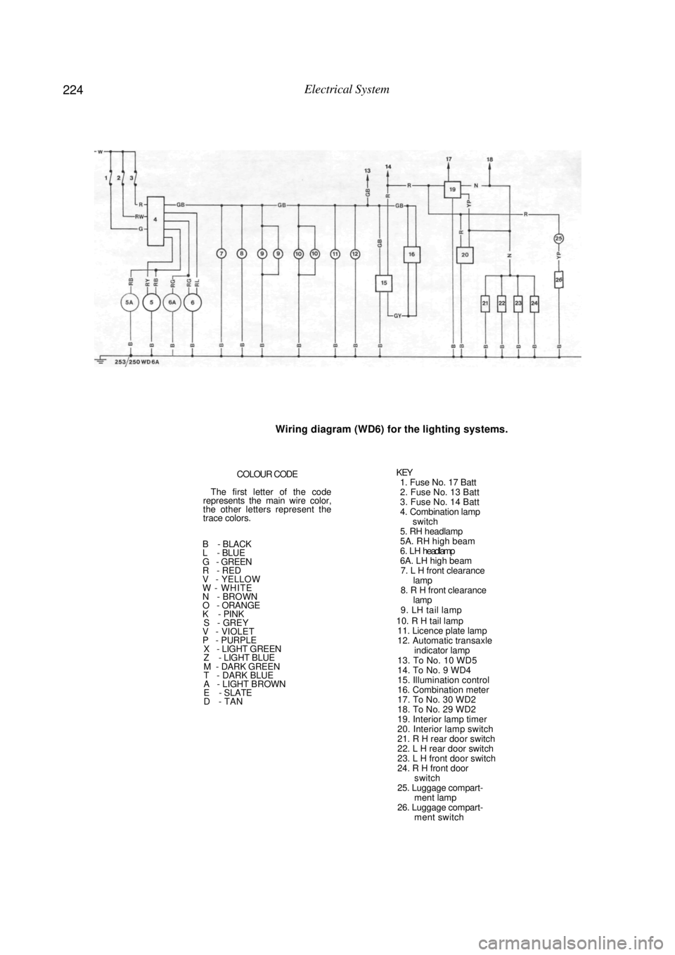
Wiring diagram (WD6) for the lighting systems.
COLOUR CODE
The first letter of the code
represents the main wire color,
the other letters represent the
trace colors.
B - BLACK
L - BLUE
G - GREEN
R - RED
V - YELLOW
W - WHITE
N - BROWN
O - ORANGE
K - PINK
S - GREY V - VIOLET
P - PURPLE X - LIGHT GREEN
Z - LIGHT BLUE
M - DARK GREEN
T - DARK BLUE
A - LIGHT BROWN
E - SLATE
D - TAN
KEY 1. Fuse No. 17 Batt
2. Fuse No. 13 Batt
3. Fuse No. 14 Batt
4. Combination lamp
switch
5. RH headlamp
5A. RH high beam
6 . L H headlamp
6A. LH high beam 7. L H front clearance lamp
8. R H front clearance lamp
9. LH tail lamp
10. R H tail lamp 11. Licence plate lamp
12. Automatic transaxle indicator lamp
13. To No. 10 WD5
14. To No. 9 WD4
15. Illumination control
16. Combination meter
17. To No. 30 WD2
18. To No. 29 WD2
19. Interior lamp timer
20. Interior lamp switch
21. R H rear door switch
22. L H rear door switch
23. L H front door switch
24. R H front door switch
25. Luggage compart- ment lamp
26. Luggage compart- ment switch