interior NISSAN PULSAR 1987 Workshop Manual
[x] Cancel search | Manufacturer: NISSAN, Model Year: 1987, Model line: PULSAR, Model: NISSAN PULSAR 1987Pages: 238, PDF Size: 28.91 MB
Page 34 of 238
Roadside Trouble Shooting
ing the wiring from any component, ensure
that the ignition switch is off and the
negative battery terminal is disconnected to
prevent damage to the solid state circuitry.
(4) Open the electrode gap of a serviceable spark
plug to 6 mm. Securely earth the plug using a jumper
lead or by tying the plug to an earthed engine
component.
(5) Disconnect the high tension lead from a
spark plug and connect it to the test spark plug.
(6) Have an assistant operate the starter motor.
(7) Check that a spark, if any, jumps the gap on
the test spark plug. If the spark is satisfactory, proceed to operation
(8).
If there is no spark, proceed as follows:
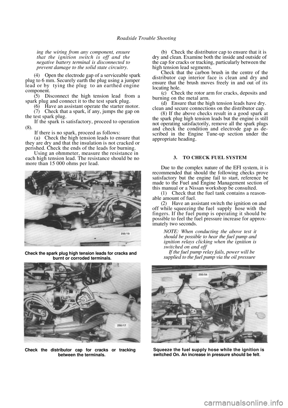
(a) Check the high tension leads to ensure that
they are dry and that the insulation is not cracked or
perished. Check the ends of the leads for burning. Using an ohmmeter, measure the resistance in
each high tension lead. The resistance should be no
more than 15 000 ohms per lead.
(b) Check the distributor cap to ensure that it is
dry and clean. Examine both the inside and outside of
the cap for cracks or tracki ng, particularly between the
high tension lead segments.
Check that the carbon brush in the centre of the
distributor cap interior fa ce is clean and dry and
ensure that the brush moves freely in and out of its
locating hole.
(c) Check the rotor arm for cracks, deposits and
burning on the metal arm. (d) Ensure that the high tension leads have dry.
clean and secure connections on the distributor cap. (8) If the above checks r esult in a good spark at
the spark plug high tension leads but the engine is still
not operating satisfac torily, remove all the spark plugs
and check the condition and electrode gap as de-
scribed in the Engine Tune-up section under the
appropriate heading.
3. TO CHECK FUEL SYSTEM
Due to the complex nature of the EFI system, it is
recommended that should the following checks prove
satisfactory but the engine fail to start, reference be
made to the Fuel and Engine Management section of
this manual or a Nissan workshop be consulted.
(1) Check that the fuel tank contains a reason-
able amount of fuel. (2) Have an assistant switch the ignition on and
off while squeezing the fuel supply hose with the
fingers. If the fuel pump is operating it should be
possible to feel the fuel pr essure increase for approx-
imately two seconds.
NOTE: When conducting the above test it
should be possible to hear the fuel pump and
ignition relays clicking when the ignition is
switched on and off
If the fuel pump relay fails, power will be
supplied to the fuel pump via the oil pressure
Check the distributor cap for cracks or tracking between the terminals. Squeeze the fuel supply hose while the ignition is
switched On. An increase in pressure should be felt.
Check the spark plug high tension leads for cracks and
burnt or corroded terminals.
Page 68 of 238
68
COOLING AND HEATING SYSTEMS
SPECIFICATIONS
Coolant capacity ........................................ 6.0 liters
Thermostat:
Opening temperature........................... 91 deg
C
Fully open temperature .................... 103 deg
C
Cooling fan:
Fan cut in temperat ure ....................... 100 deg C
Fan cut out temperature ...................... 95 deg C
Radiator cap opening
pressure ................................................... 78 -98 kPa
TORQUE WRENCH SETTINGS
Water pump retaining bolts .............................25 Nm
Thermostat housing bolts .................................15 Nm
Sender unit .......................................................10 Nm
1. COOLING SYSTEM TROUBLE SHOOTING
COOLANT LEAKAGE - EXTERNAL
(1) Loose hose clips or faulty hoses: Tighten the
hose clips or renew the faulty water hoses.
(2) Leaking radiator core or tanks: Repair or
renew the radiator. (3) Leaking heater core or hoses: Repair or renew the heater core. Check the hose clips and hoses
and renew if necessary.
(4)
Leaks at the thermostat cover and/or water
pump O rings. Renew the O rings. (5) Worn or damaged water pump seal assembly:
Renew the water pump. (6) Worn or damaged water pump bearing as-
sembly: Renew the water pump.
(7) Loose or rusted welch plugs; Renew the
welch plugs. (8) Faulty cylinder head gasket or loose cylinder
head bolts: Renew the cylinder head gasket and
correctly tighten the cylinder head bolts. (9) External crack in the cy linder head or cylin-
der block: Repair or renew the faulty components.
NOTE: Check the system for external leak-
age by running the engine to operating
temperature over a dry floor and checking
for the leak source.
Check the vehicle interior below the
heater core for moisture. If a rusted welch
plug is found, it is a good practice to renew
all the welch plugs.
COOLANT LEAKAGE - INTERNAL
( 1 ) Cylinder head gasket leak due to warped
cylinder head or cylinder block gasket faces: Reface
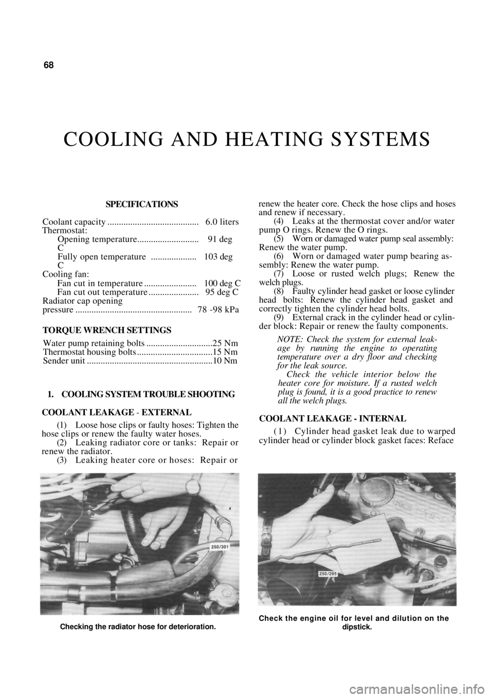
Checking the radiator hose for deterioration.
Check the engine oil for level and dilution on the
dipstick.
Page 77 of 238
Cooling and Heating Systems 77
These openings are plugged with welch plugs. The
plugs may have to be renewed when cleaning the
engine water jackets or when defective due to corro-
sion.
TO RENEW
NOTE: If a welch plug is found to be
corroded it is good policy to renew all the
welch plugs.
(1) Drain the radiator and cylinder block.
(2) Remove the necessary engine components or
accessories to gain ampl e working space around the
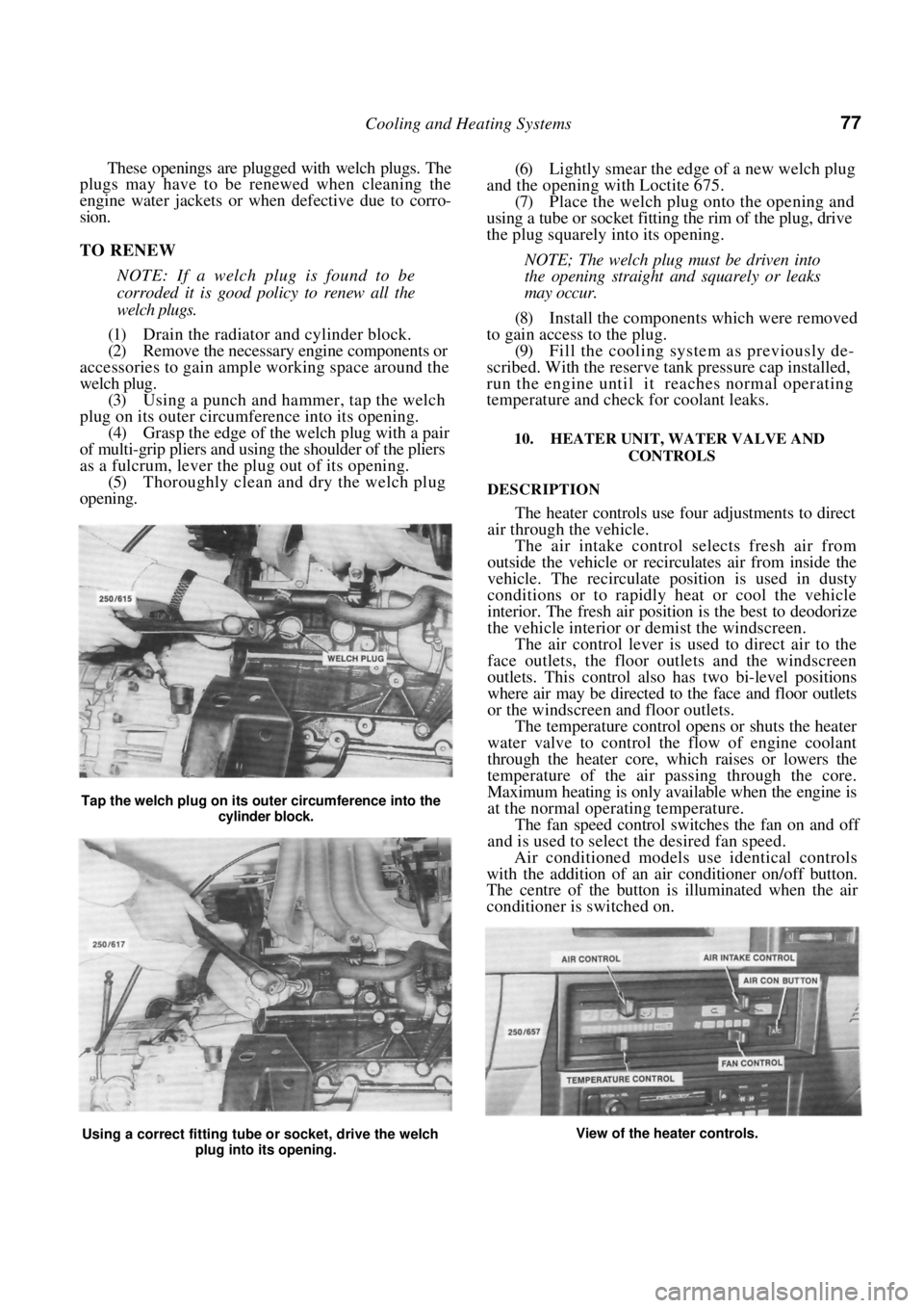
welch plug. (3) Using a punch and hammer, tap the welch
plug on its outer circumference into its opening. (4) Grasp the edge of the welch plug with a pair
of multi-grip pliers and using the shoulder of the pliers
as a fulcrum, lever the plug out of its opening. (5) Thoroughly clean and dry the welch plug
opening.
(6) Lightly smear the edge of a new welch plug
and the opening with Loctite 675. (7) Place the welch plug onto the opening and
using a tube or socket fitting the rim of the plug, drive
the plug squarely into its opening.
NOTE; The welch plug must be driven into
the opening straight and squarely or leaks
may occur.
(8) Install the components which were removed
to gain access to the plug. (9) Fill the cooling system as previously de-
scribed. With the reserve tank pressure cap installed,
run the engine until it reaches normal operating
temperature and check for coolant leaks.
10. HEATER UNIT, WATER VALVE AND
CONTROLS
DESCRIPTION
The heater controls use four adjustments to direct
air through the vehicle.
The air intake control selects fresh air from
outside the vehicle or recirculates air from inside the
vehicle. The recirculate position is used in dusty
conditions or to rapidly heat or cool the vehicle
interior. The fresh air positi on is the best to deodorize
the vehicle interior or demist the windscreen.
The air control lever is used to direct air to the
face outlets, the floor outle ts and the windscreen
outlets. This control also has two bi-level positions
where air may be directed to the face and floor outlets
or the windscreen and floor outlets.
The temperature control opens or shuts the heater
water valve to control the flow of engine coolant
through the heater core, which raises or lowers the
temperature of the air passing through the core.
Maximum heating is only available when the engine is
at the normal operating temperature.
The fan speed control switches the fan on and off
and is used to select the desired fan speed.
Air conditioned models use identical controls
with the addition of an air conditioner on/off button.
The centre of the button is illuminated when the air
conditioner is switched on.
Tap the welch plug on its ou ter circumference into the
cylinder block.
Using a correct fitting tube or socket, drive the welch
plug into its opening. View of the heater controls.
Page 214 of 238
214 Electrical System
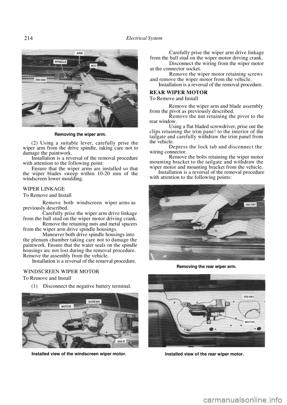
Removing the wiper arm.
(2) Using a suitable lever, carefully prise the
wiper arm from the drive spindle, taking care not to
damage the paintwork.
Installation is a reversal of the removal procedure
with attention to the following point:
Ensure that the wiper arms are installed so that
the wiper blades sweep within 10-20 mm of the
windscreen lower moulding.
WIPER LINKAGE
To Remove and Install
Remove both windscreen wiper arms as
previously described.
Carefully prise the wiper arm drive linkage
from the ball stud on the wiper motor driving crank. Remove the retaining nuts and metal spacers
from the wiper arm dr ive spindle housings.
Maneuver both drive spindle housings into
the plenum chamber taking care not to damage the
paintwork. Ensure that th e water seals on the spindle
housings arc not lost during the removal procedure.
Remove the assembly from the vehicle. Installation is a reversal of the removal procedure.
WINDSCREEN WIPER MOTOR
To Remove and Install
(1) Disconnect the negative battery terminal.
Carefully prise the wiper arm drive linkage
from the ball stud on the wiper motor driving crank.
Disconnect the wiring from the wiper motor
at the connector socket. Remove the wiper motor retaining screws
and remove the wiper motor from the vehicle. Installation is a reversal of the removal procedure.
REAR WIPER MOTOR
To Remove and Install
Remove the wiper arm and blade assembly
from the pivot as previously described. Remove the nut retaining the pivot to the
rear window. Using a flat bladed screwdriver, prise out the
clips retaining the trim pane! to the interior of the
tailgate and carefully wit hdraw the trim panel from
the vehicle. Depress the lock tab and disconnect the
wiring connector. Remove the bolts retaining the wiper motor
mounting bracket to the tailgate and withdraw the
wiper motor and mounting bracket from the vehicle.
Installation is a reversal of the removal procedure
with attention to the following points:
Installed view of the windscreen wiper motor.
Installed view of the rear wiper motor.
Removing the rear wiper arm.
Page 224 of 238
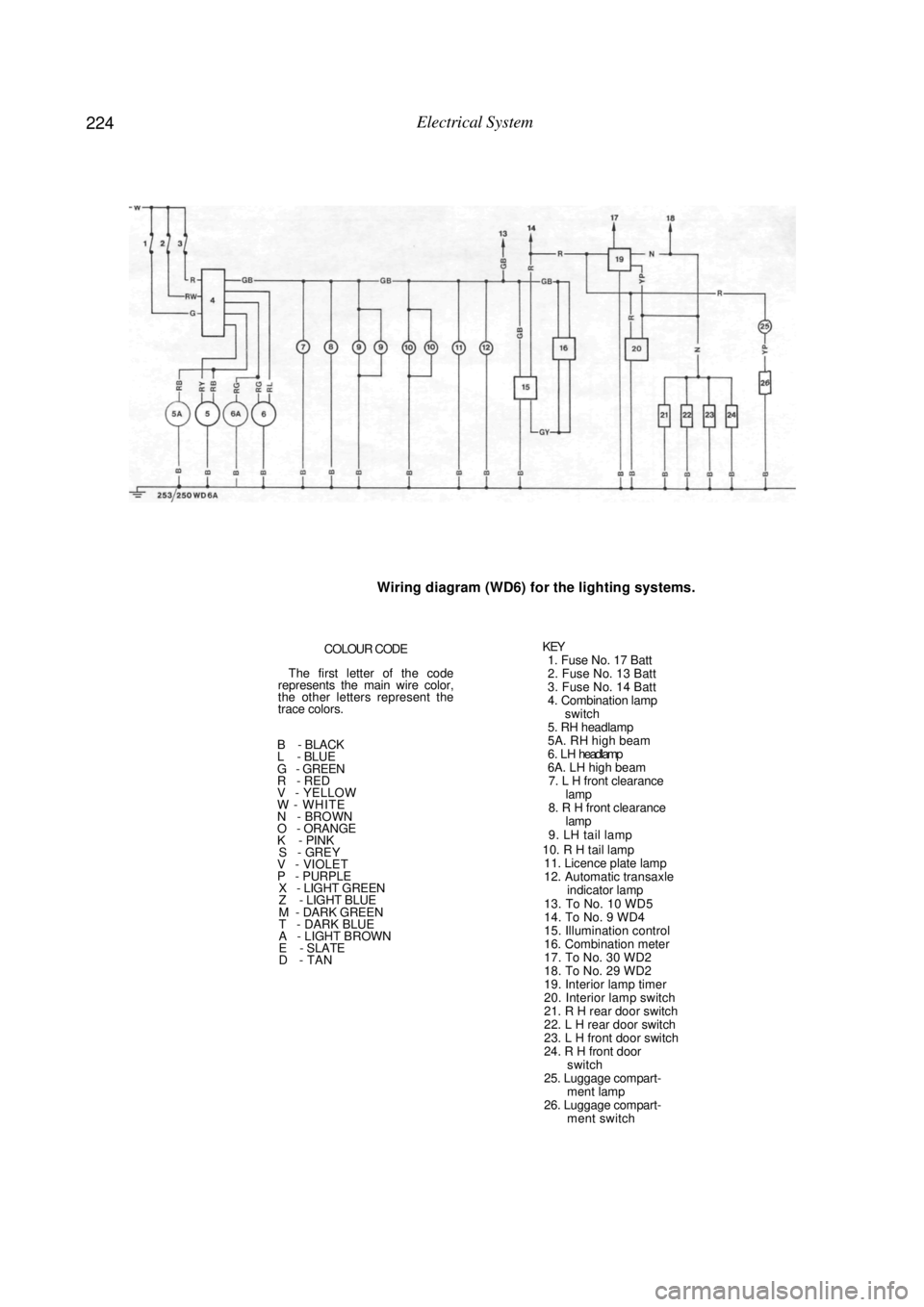
224 Electrical System
Wiring diagram (WD6) for the lighting systems.
COLOUR CODE
The first letter of the code
represents the main wire color,
the other letters represent the
trace colors.
B - BLACK
L - BLUE
G - GREEN
R - RED
V - YELLOW
W - WHITE
N - BROWN
O - ORANGE
K - PINK
S - GREY V - VIOLET
P - PURPLE X - LIGHT GREEN
Z - LIGHT BLUE
M - DARK GREEN
T - DARK BLUE
A - LIGHT BROWN
E - SLATE
D - TAN
KEY 1. Fuse No. 17 Batt
2. Fuse No. 13 Batt
3. Fuse No. 14 Batt
4. Combination lamp
switch
5. RH headlamp
5A. RH high beam
6 . L H headlamp
6A. LH high beam 7. L H front clearance lamp
8. R H front clearance lamp
9. LH tail lamp
10. R H tail lamp 11. Licence plate lamp
12. Automatic transaxle indicator lamp
13. To No. 10 WD5
14. To No. 9 WD4
15. Illumination control
16. Combination meter
17. To No. 30 WD2
18. To No. 29 WD2
19. Interior lamp timer
20. Interior lamp switch
21. R H rear door switch
22. L H rear door switch
23. L H front door switch
24. R H front door switch
25. Luggage compart- ment lamp
26. Luggage compart- ment switch
Page 225 of 238
225
BODY
1. WINDSCREEN AND REAR GLASS
The renewal or replacement of the windscreen
and the rear glass follows the same basic procedure.
The successful installation and sealing of the
windscreen or rear glass will depend to a large extent
on the technical knowledge and experience of the
operator and it is not recomm ended that rear glass or
windscreen replacement be attempted by anyone
lacking in previous experience.
2. FRONT DOORS
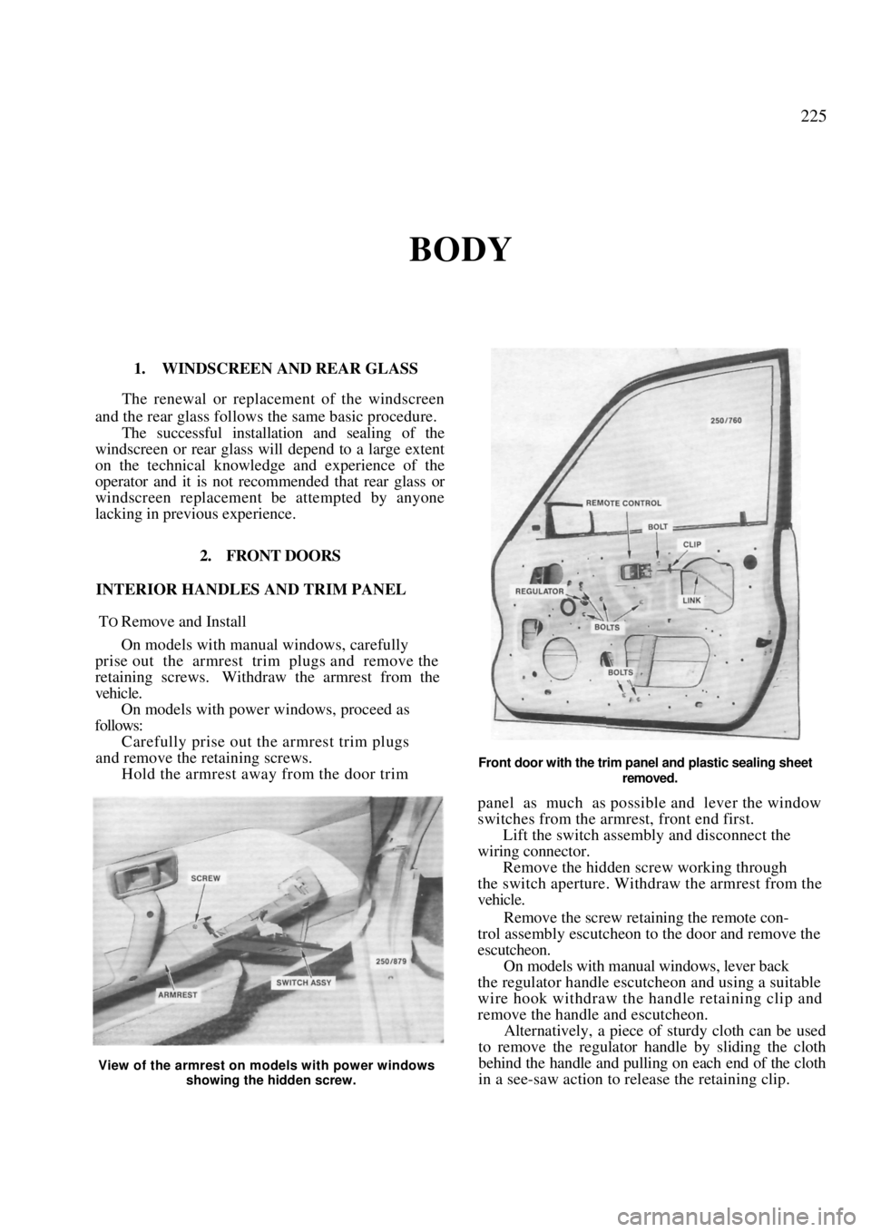
INTERIOR HANDLES AND TRIM PANEL
TO Remove and Install
On models with manual windows, carefully
prise out the armrest trim plugs and remove the
retaining screws. Withdraw the armrest from the
vehicle. On models with power windows, proceed as
follows: Carefully prise out the armrest trim plugs
and remove the retaining screws. Hold the armrest away from the door trim
Front door with the trim panel and plastic sealing sheet
removed.
panel as much as possible and lever the window
switches from the armrest, front end first.
Lift the switch assembly and disconnect the
wiring connector. Remove the hidden screw working through
the switch aperture. Withdraw the armrest from the
vehicle.
Remove the screw retaining the remote con-
trol assembly escutcheon to the door and remove the
escutcheon.
On models with manual windows, lever back
the regulator handle escutcheon and using a suitable
wire hook withdraw the handle retaining clip and
remove the handle and escutcheon. Alternatively, a piece of sturdy cloth can be used
to remove the regulator handle by sliding the cloth
behind the handle and pulling on each end of the cloth
in a see-saw action to release the retaining clip.
View of the armrest on models with power windows
showing the hidden screw.
Page 226 of 238
226 Body
Remove the screws retaining the speaker to
the trim panel, withdraw the speaker slightly and
disconnect the wiring connector at the rear. Place the
speaker to one side clear of the work area.
On models with a step lamp located in the
door trim panel, remove the screws, withdraw the step
lamp and disconnect the wiring connector. Using a broad bladed screwdriver, carefully
lever the trim panel outwa rds and disengage all the
retaining clips. When all the clips have been disen-
gaged maneuver the trim panel from the door. Remove the screw retaining the speaker
water deflector to the inner door panel and withdraw
the water deflector.
Carefully remove the plastic sealing sheet from
the inner door panel.
Installation is a reversal of the removal procedure
with attention to the following points:
Ensure that the plastic sealing sheet is cor-
rectly installed and not torn or damaged.
Check the trim panel retaining clips and
renew any damaged clips as necessary. On models with manual windows, wind the
door glass to the closed position, install the
retaining
clip to the regulator handle and install the regulator
handle to correspond with the regulator handle on the
opposite door.
DOOR GLASS AND REGULATOR
To Remove and Install
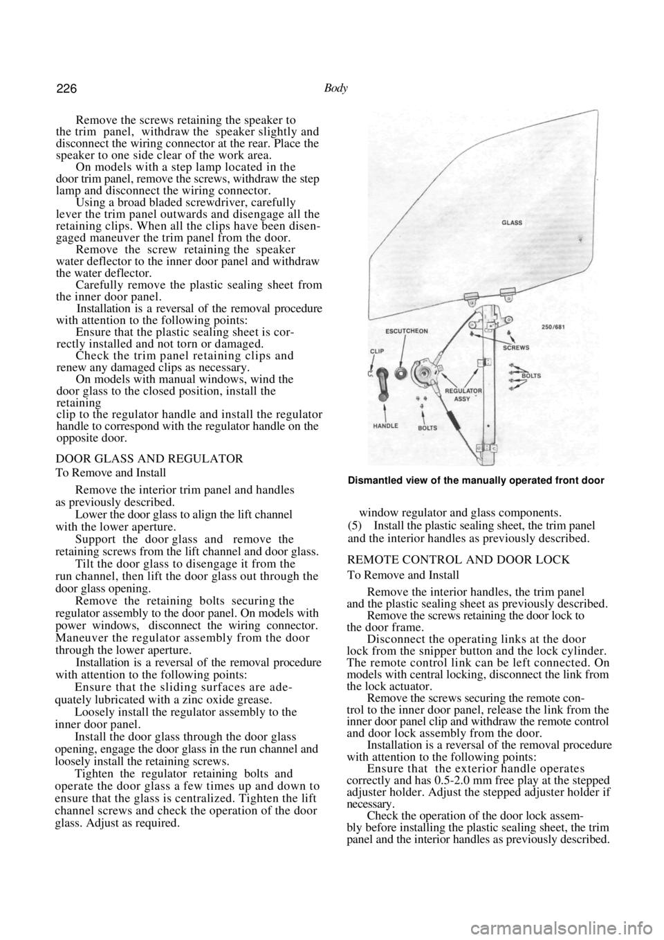
Remove the interior trim panel and handles
as previously described. Lower the door glass to align the lift channel
with the lower aperture. Support the door glass and remove the
retaining screws from the lift channel and door glass. Tilt the door glass to disengage it from the
run channel, then lift the door glass out through the
door glass opening. Remove the retaining bolts securing the
regulator assembly to the door panel. On models with
power windows, disconnect the wiring connector.
Maneuver the regulator assembly from the door
through the lower aperture. Installation is a reversal of the removal procedure
with attention to the following points:
Ensure that the sliding surfaces are ade-
quately lubricated with a zinc oxide grease.
Loosely install the regulator assembly to the
inner door panel. Install the doo r glass through the door glass
opening, engage the door glass in the run channel and
loosely install the retaining screws.
Tighten the regulator retaining bolts and
operate the door glass a few times up and down to
ensure that the glass is centralized. Tighten the lift
channel screws and check the operation of the door
glass. Adjust as required.
Dismantled view of the manually operated front door
window regulator and glass components.
(5) Install the plastic sealing sheet, the trim panel
and the interior handles as previously described.
REMOTE CONTROL AND DOOR LOCK
To Remove and Install
Remove the interior handles, the trim panel
and the plastic sealing sheet as previously described.
Remove the screws retaining the door lock to
the door frame. Disconnect the operating links at the door
lock from the snipper button and the lock cylinder.
The remote control link can be left connected. On
models with central locking, disconnect the link from
the lock actuator.
Remove the screws securing the remote con-
trol to the inner door panel, release the link from the
inner door panel clip and w ithdraw the remote control
and door lock assembly from the door. Installation is a reversal of the removal procedure
with attention to the following points:
Ensure that the exterior handle operates
correctly and has 0.5-2.0 mm free play at the stepped
adjuster holder. Adjust the stepped adjuster holder if
necessary. Check the operation of the door lock assem-
bly before installing the plastic sealing sheet, the trim
panel and the interior handles as previously described.
Page 227 of 238

Body 227
Dismantled view of the front door lock components. Dimension A at the stepped adjuster holder should be 0.5-2.0 mm. Turn the stepped adjuster holder to give the correct free play.
EXTERIOR DOOR HANDLE
To Remove and Install
Remove the interior handles, the trim panel
and the plastic sealing sheet as previously described.
Remove the retaining nuts from inside the
door panel. Withdraw the handle slightly while ensur-
ing that the link is sliding out of the lock assembly.
Maneuver the exterior handle from the vehicle. Installation is a reversal of the removal procedure
with attention to the following points:
Ensure that the exterior handle and seal are
in a serviceable condition and installed correctly to
prevent the entry of dust and water. Ensure that the exterior handle operates
correctly and has 0.5-2.0 mm free play at the stepped
adjuster holder. Adjust the stepped adjuster holder if
necessary.
Check the operation of the door lock assem-
bly before installing the plastic sealing sheet, the trim
panel and the interior handles as previously described.
LOCK CYLINDER
To Remove and Install
(1) Remove the interior handles, the trim panel
and the plastic sealing sheet as previously described.
Wind the door glass up fully and disconnect
the operating link between the door lock and the lock
cylinder.
Using a suitable screwdriver, remove the
lock cylinder retaining clip and withdraw the lock
cylinder from the outer door panel.
Installation is a reversal of the removal
procedure.
LOCK STRIKER PLATE
To Remove, Install and Adjust
Mark the position of the striker plate on the
door pillar with a soft lead pencil to facilitate correct
replacement of the striker plate.
Remove the retaining screws from the striker
plate to the door pillar and remove the striker plate.
Inspect the striker plate for wear and renew as
necessary.
Install the striker plate to the door pillar
according to the pencil marks made on removal.
Close the door and observe the alignment
with the body panel or rear door. If necessary, loosen
the striker plate retaining screws and move the striker
plate in or out to achieve a flush fit. If the door lifts or drops when the lock
Page 228 of 238
228 Body
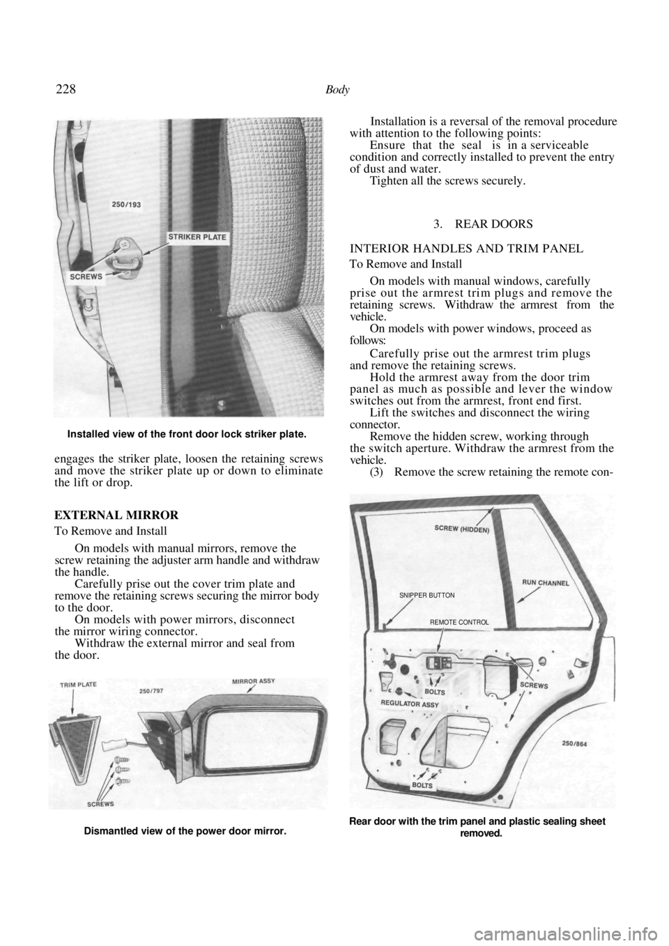
Installed view of the front door lock striker plate.
engages the striker plate, loosen the retaining screws
and move the striker plate up or down to eliminate
the lift or drop.
Installation is a reversal of the removal procedure
with attention to the following points:
Ensure that the seal is in a serviceable
condition and correctly installed to prevent the entry
of dust and water. Tighten all the screws securely.
3. REAR DOORS
INTERIOR HANDLES AND TRIM PANEL
To Remove and Install
On models with manual windows, carefully
prise out the armrest trim plugs and remove the
retaining screws. Withdraw the armrest from the
vehicle. On models with power windows, proceed as
follows:
Carefully prise out the armrest trim plugs
and remove the retaining screws. Hold the armrest away from the door trim
panel as much as possible and lever the window
switches out from the armrest, front end first.
Lift the switches and disconnect the wiring
connector. Remove the hidden screw, working through
the switch aperture. Withdraw the armrest from the
vehicle. (3) Remove the screw retaining the remote con-
EXTERNAL MIRROR
To Remove and Install
On models with manual mirrors, remove the
screw retaining the adjuster arm handle and withdraw
the handle. Carefully prise out the cover trim plate and
remove the retaining screws securing the mirror body
to the door. On models with power mirrors, disconnect
the mirror wiring connector. Withdraw the external mirror and seal from
the door.
Rear door with the trim panel and plastic sealing sheet
removed.
SNIPPER BUTTON
REMOTE CONTROL
Dismantled view of the power door mirror.
Page 229 of 238
Body 229
trol assembly escutcheon to the door and remove the
escutcheon.
(4) On models with manual windows, lever back
the regulator handle escutcheon and using a suitable
wire hook, withdraw the handle retaining clip and
remove the handle and escutcheon.
Alternatively, a piece of sturdy cloth can be used
to remove the regulator handle by sliding the cloth
behind the handle and pulling on each end of the cloth
in a see-saw action to release the retaining clip.
On models with a step lamp located in the
door trim panel, remove the screws, withdraw the
lamp and disconnect the wiring connector. Using a broad bladed screwdriver, carefully
lever the trim panel outwa rds and disengage all the
retaining clips. When all the clips have been disen-
gaged maneuver the trim panel from the door. Carefully remove the plastic sealing sheet
from the inner door panel. Installation is a reversal of the removal procedure
with attention to the following points:
Ensure that the plastic sealing sheet is cor-
rectly installed and not torn or damaged. Check the trim panel retaining clips and
renew any damaged clips as necessary. On models with manual windows, wind the
door glass to the closed position, install the
retaining
clip to the regulator handle and install the regulator
handle to correspond with the regulator handle on the
opposite door.
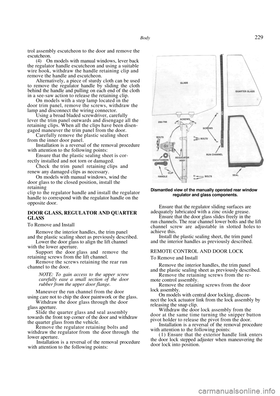
DOOR GLASS, REGULATOR AND QUARTER
GLASS
To Remove and Install
Remove the interior handles, the trim panel
and the plastic scaling sheet as previously described. Lower the door glass to align the lift channel
with the lower aperture.
Support the door glass and remove the
retaining screws from the lift channel.
Remove the screws retaining the rear run
channel to the door.
NOTE: To gain a ccess to the upper screw
carefully ease a small section of the door
rubber from the upper door flange.
Maneuver the run channel from the door
using care not to chip the d oor paintwork or the glass.
Withdraw the door glass through the door
glass aperture. Slide the quarter glass and seal assembly
towards the front top corner of the door and withdraw
the quarter glass from the vehicle. Remove the regulator retaining bolts and
withdraw the regulator from the door through the
lower aperture. Installation is a reversal of the removal procedure
with attention to the following points:
Dismantled view of the manually operated rear window
regulator and glass components.
Ensure that the regulator sliding surfaces are
adequately lubricated with a zinc oxide grease. Ensure that the door glass slides freely in the
run channels. The rear channe l lower bolts and the lift
channel screw are adjustable in slotted holes to
achieve this. Install the plastic sealing sheet, the trim panel
and the interior handles as previously described.
REMOTE CONTROL AND DOOR LOCK
To Remove and Install
Remove the interior handles, the trim panel
and the plastic sealing sheet as previously described. Remove the retaining screws from the re-
mote control assembly.
Remove the retaining screws from the door
lock assembly. On models with central door locking, discon-
nect the lock actuator li nk from the lock assembly by
releasing the snap clip. Withdraw the door lock assembly from the
door at the same time turning the snipper button
pivot holder to release the pivot from the door. Installation is a reversal of the removal procedure
with attention to the following points:
(1) Ensure that the exterior handle link enters
the door lock stepped adjuster when maneuvering the
door lock into position.