jack points NISSAN PULSAR 1987 Workshop Manual
[x] Cancel search | Manufacturer: NISSAN, Model Year: 1987, Model line: PULSAR, Model: NISSAN PULSAR 1987Pages: 238, PDF Size: 28.91 MB
Page 10 of 238
10 General Information
If tools are to be stored for any length of time, it is
good policy to wipe them with an oily cloth.
Bladed screwdrivers should be checked for dam-
age to the tip. If necessary, the tip can be returned to
its original profile by careful grinding. Do not grind
screwdriver tips to a sharp point.
Hammer heads should be secure on their handles
and should be regularly checked for cracking or other
damage.
Chisels and punches should be checked for dam-
age or 'mushrooming' of the head. Any faults should
be rectified by grinding.
Hydraulic jacks should be regularly checked for
fluid leaks. Chassis stands and car ramps should be
checked for damage and cracks. Any equipment that
is suspect should not be used.
STORES
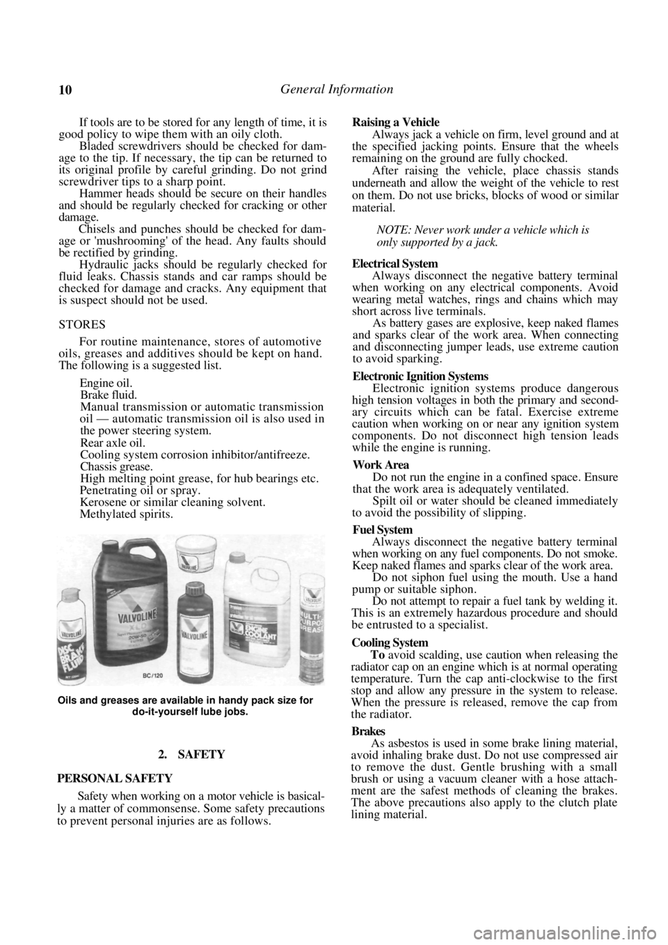
For routine maintenance, stores of automotive
oils, greases and additives should be kept on hand.
The following is a suggested list.
Engine oil.
Brake fluid.
Manual transmission or automatic transmission
oil — automatic transmission oil is also used in
the power steering system.
Rear axle oil.
Cooling system corrosion inhibitor/antifreeze.
Chassis grease.
High melting point grease, for hub bearings etc.
Penetrating oil or spray.
Kerosene or similar cleaning solvent.
Methylated spirits.
Oils and greases are available in handy pack size for
do-it-yourself lube jobs.
2. SAFETY
PERSONAL SAFETY
Safety when working on a motor vehicle is basical-
ly a matter of commonsense. Some safety precautions
to prevent personal in juries are as follows.
Raising a Vehicle
Always jack a vehicle on firm, level ground and at
the specified jacking points . Ensure that the wheels
remaining on the ground are fully chocked.
After raising the vehicle, place chassis stands
underneath and allow the weight of the vehicle to rest
on them. Do not use bricks, blocks of wood or similar
material.
NOTE: Never work under a vehicle which is
only supported by a jack.
Electrical System
Always disconnect the negative battery terminal
when working on any electrical components. Avoid
wearing metal watches, rings and chains which may
short across live terminals.
As battery gases are explosive, keep naked flames
and sparks clear of the work area. When connecting
and disconnecting jumper leads, use extreme caution
to avoid sparking.
Electronic Ignition Systems
Electronic ignition systems produce dangerous
high tension voltages in bo th the primary and second-
ary circuits which can be fatal. Exercise extreme
caution when working on or near any ignition system
components. Do not disconnect high tension leads
while the engine is running.
Work Area
Do not run the engine in a confined space. Ensure
that the work area is adequately ventilated.
Spilt oil or water should be cleaned immediately
to avoid the possibility of slipping.
Fuel System
Always disconnect the negative battery terminal
when working on any fuel components. Do not smoke.
Keep naked flames and sparks clear of the work area.
Do not siphon fuel using the mouth. Use a hand
pump or suitable siphon.
Do not attempt to repair a fuel tank by welding it.
This is an extremely hazardous procedure and should
be entrusted to a specialist.
Cooling System
To avoid scalding, use caution when releasing the
radiator cap on an engine wh ich is at normal operating
temperature. Turn the cap anti-clockwise to the first
stop and allow any pressure in the system to release.
When the pressure is released, remove the cap from
the radiator.
Brakes
As asbestos is used in some brake lining material,
avoid inhaling brake dust. Do not use compressed air
to remove the dust. Gentle brushing with a small
brush or using a vacuum cleaner with a hose attach-
ment are the safest methods of cleaning the brakes.
The above precautions also apply to the clutch plate
lining material.
Page 14 of 238
14
LUBRICATION AND MAINTENANCE
SPECIFICATIONS
CAPACITY AND GRADE
Engine:
Lubricant........................................... 15W-50 SF
Sump capacity including filter ........... 3.3 liters
Cooling system capacity............................ 6.0 liters
Manual transaxle:
Lubricant....................................... 80W-90 GL-4
Capacity ............................................... 2.7 liters
Automatic transaxle:
Lubricant.............................................. Dexron II
Capacity ............................................... 6.0 liters
Power steering:
Lubricant.............................................. Dexron II
Capacity ............................................... 1.0 liters
Manual steering lubricant ........ Castrol EPLl grease
Brake fluid type ................................................ Dot 4
1. HOW TO GREASE AND OIL CHANGE
(1) Run the front of the vehicle onto car ramps
and stop the engine. Chock the front wheels. (2) Raise the rear of the vehicle and place
chassis stands under the rear jacking points.
NOTE: It is best if the vehicle is kept as level
as possible to avoi d false readings when
checking the lubricant levels.
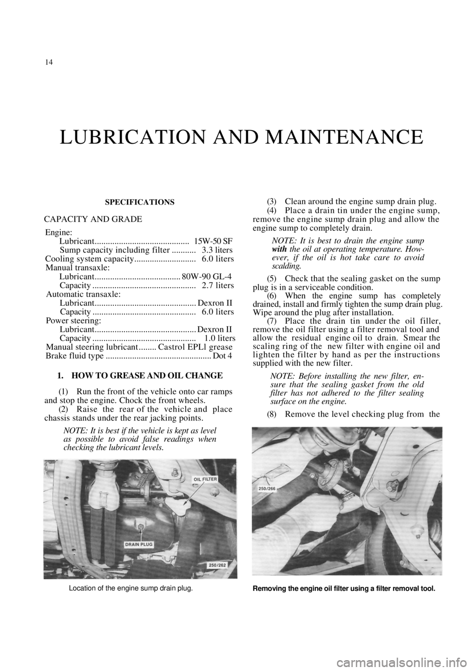
(3) Clean around the engine sump drain plug.
(4) Place a drain tin under the engine sump,
remove the engine sump drain plug and allow the
engine sump to completely drain.
NOTE: It is best to drain the engine sump
with the oil at operating temperature. How-
ever, if the oil is hot take care to avoid
scalding.
(5) Check that the sealing gasket on the sump
plug is in a serviceable condition. (6) When the engine sump has completely
drained, install and firmly tighten the sump drain plug.
Wipe around the plug after installation. (7) Place the drain tin under the oil filler,
remove the oil filter using a filter removal tool and
allow the residual engine oil to drain. Smear the
scaling ring of the new filter with engine oil and
lighten the filter by hand as per the instructions
supplied with the new filter.
NOTE: Before installing the new filter, en-
sure that the sealing gasket from the old
filter has not adhered to the filter sealing
surface on the engine.
(8) Remove the level checking plug from the
Location of the engine sump drain plug.
Removing the engine oil filter using a filter removal tool.
Page 21 of 238
WHEELS AND TYRES
SPECIFICATIONS
TYRES PRESSURES
Front:
Normal load ............................................ 200 kPa
Heavy load or high speed ......................230 kPa
Rear:
Normal load............................................ 180 kPa
Heavy load or high speed ...................... 210 kPa
NOTE: The above pressures are measured
cold and are meant as a guide only. Always
refer to the tire placard positioned on the
inside of the glove compartment lid and the
tire manufacturers recommendations first.
TORQUE WRENCH SETTINGS
Wheel nut torque .............................................98 Nm
1. HOW TO CHANGE A ROAD WHEEL
(1) Ensure that the vehicle is on level firm
ground and clear of any passing traffic. (2) If necessary, switch on the hazard
flashers.
(3) Switch off the engine a nd place the transaxle
in the (P) Park position on automatic transaxle
models or in reverse gear on manual transaxle models.
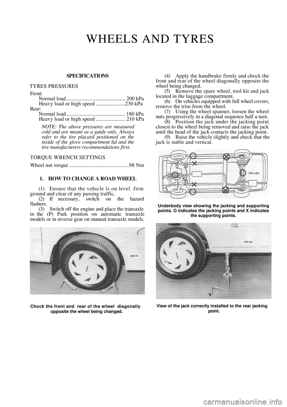
(4) Apply the handbrake firmly and chock the
front and rear of the wheel diagonally opposite the
wheel being changed.
(5) Remove the spare wheel, tool kit and jack
located in the luggage compartment. (6) On vehicles equipped with full wheel covers,
remove the trim from the wheel. (7) Using the wheel spanner, loosen the wheel
nuts progressively in a diagonal sequence half a turn.
(8) Position the jack und er the jacking point
closest to the wheel being removed and raise the jack
until the head of the jack contacts the jacking point.
(9) Raise the vehicle slightly and check that the
jack is stable and vertical.
Underbody view showing the jacking and supporting
points. O indicates the jacking points and X indicates
the supporting points.
Chock the front and rear of the wheel diagonally
opposite the wheel being changed. View of the jack correctly installed to the rear jacking
point.
Page 64 of 238
64 Engine
automatic transaxle models the complete drive plate
must be renewed.
(3) Inspect the drive plate bolt holes for elonga-
tion which is caused by loose retaining bolts.
(4) Inspect the drive plate for cracks.
(5) Repair or renew the flywheel if necessary.
TO INSTAL
Installation is a reversal of the removal procedure
with attention to the following points:
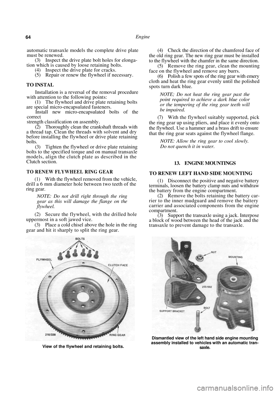
(1) The flywheel and drive plate retaining bolts
are special micro-encapsulated fasteners.
Install new micro-encapsulated bolts of the
correct
strength classification on assembly.
(2) Thoroughly clean the crankshaft threads with
a thread tap. Clean the threads with solvent and dry
before installing the flywh eel or drive plate retaining
bolts.
(3) Tighten the flywheel or drive plate retaining
bolts to the specified torque and on manual transaxle
models, align the clutch plate as described in the
Clutch section.
TO RENEW FLYWHEEL RING GEAR
(1) With the flywheel removed from the vehicle,
drill a 6 mm diameter hole between two teeth of the
ring gear.
NOTE: Do not drill right through the ring
gear as this will damage the flange on the
flywheel.
(2) Secure the flywheel, with the drilled hole
uppermost in a soft jawed vice.
(3) Place a cold chisel above the hole in the ring
gear and hit it sharply to split the ring gear.
(4) Check the direction of the chamfered face of
the old ring gear. The new ring gear must be installed
to the flywheel with the chamfer in the same direction. (5) Remove the ring gear, clean the mounting
face on the flywheel and remove any burrs. (6) Polish a few spots of the ring gear with emery
cloth and heat the ring gear evenly until the polished
spots turn dark blue.
NOTE; Do not heat the ring gear past the
point required to achieve a dark blue color
or the tempering of the ring gear teeth will
be impaired.
(7) With the flywheel suitably supported, pick
the ring gear up using plie rs, and place it evenly onto
the flywheel. Use a hammer and a brass drift to ensure
that the ring gear seats ag ainst the flywheel flange.
NOTE: Allow the ring gear to cool slowly.
Do not quench it in water.
13. ENGINE MOUNTINGS
TO RENEW LEFT HAND SIDE MOUNTING
(1) Disconnect the positive and negative battery
terminals, loosen the battery clamp nuts and withdraw
the battery from the engine compartment.
(2) Remove the bolts retaining the battery car-
rier to the inner mudguard and remove the battery
carrier and associ ated components from the engine
compartment. (3) Support the transaxle using a jack. Interpose
a block of wood between the head of the jack and the
transaxle to prevent damage to the transaxle.
View of the flywheel and retaining bolts.
Dismantled view of the left hand side engine mounting
assembly installed to vehicles with an automatic tran-
saxle.
Page 76 of 238

Cooling and Heating Systems
7. THERMOSTAT HOUSING
Special Equipment Required:
To Adjust Camshaft Drive Belt — Adjusting tool
TO REMOVE AND INSTAL
(1) Disconnect the negative battery terminal.
(2) On 1.6 liter models, remove the air cleaner
assembly from the engine. Refer to the Fuel and
Engine Management section if necessary. (3) Drain the cooling system as previously de-
scribed. (4) Remove the camshaft drive belt as described
in the Engine section under the heading Camshaft
Drive Belt. (5) Remove the bolts retaining the camshaft
drive belt rear cover to the cylinder block and remove
the rear cover.
\ COOLANT TEMPERATURE SENSOR TEMPERATURE SENDER SWITCH
View of the thermostat housing and
components.
(6) Disconnect the top radi ator hose, the heater
hose and the inlet manifold heater hose from the
thermostat housing.
(7) Disconnect the wire from the temperature
sender switch and the coolant temperature sensor. (8) Remove the bolts retaining the thermostat
housing to the cylinder head and remove the thermo-
stat housing and the O ring from the cylinder head. Installation is a reversal of the removal procedure
with attention to the following points:
(1) Ensure that all mounting faces are clean.
(2) Renew the O ring on installation.
NOTE; Ensure that the O ring is not
twisted. Do not use sealant.
(3) Tighten the thermostat housing retaining
bolts to the specified torque. (4) Adjust the camshaft drive belt tension as
described in the Engine section under the heading
Camshaft Drive Belt. (5) Fill the cooling system as previously de-
scribed and check for coolant leaks. 8. WATER PUMP
Special Equipment Required:
To Adjust Camshaft Drive Belt — Adjusting tool
TO REMOVE AND INSTAL
NOTE: The water pump is non-repairable
and if faulty must be renewed as a complete
assembly.
(1)
Drain the cooling system as previously de-
scribed.
(2) Remove the camshaft drive belt as described
in the Engine section under the heading Camshaft
Drive Belt. (3) Remove the water pump retaining bolts and
remove the water pump and the O ring from the
engine. Installation is a reversal of the removal procedure
with attention to the following points:
View of the water pump and components removed
from the vehicle.
(1) Ensure that all mounting faces are clean.
(2) Use a new O ring and smear it with a liberal
amount of silicone grease.
(3) Install the water pump to the engine but
do
not tighten the retaining bolts until the camshaft drive
belt has been installed and tensioned correctly as
described in the Engine section under the heading
Camshaft Drive Belt.
(4) Fill the cooling system as previously de-
scribed in this section and check for coolant leaks.
9. WELCH PLUGS
To facilitate the casting of the cylinder block and
cylinder head passages and water jackets, a number of
openings had to be ma de at manufacture.
Page 129 of 238
Manual Transaxle and Drive Shafts 129
renewed as individual units. The C.V. joints are
lubricated in manufacture and need no attention in
service unless one of the r ubber boots is damaged. In
this case the joint can be cl eaned and repacked with
the recommended grease and a new boot installed.
From July 1989, Pulsar Q and Vector SSS manual
transaxle models are equipped with a limited slip
differential incorporating a viscous coupling. The
coupling is not repairable and must be renewed as an
assembly if unserviceable. A test procedure for the
viscous coupling is included in the text in this section.
3. TRANSAXLE ASSEMBLY
Special Equipment Required:
To Dismantle and Assemble — Puller set, press
and press plates, dial gauge
To Measure Mainshaft Turning Torque —
Suitable slotted adaptor and torque gauge
TO REMOVE AND INSTAL
(1) Raise the front of the vehicle and support it
on chassis stands.
(2) Remove the battery as described in the
Electrical System section. (3) Remove the drive shafts as described later in
this section. (4) Disconnect and remove the starter motor as
described in the Elect rical System section.
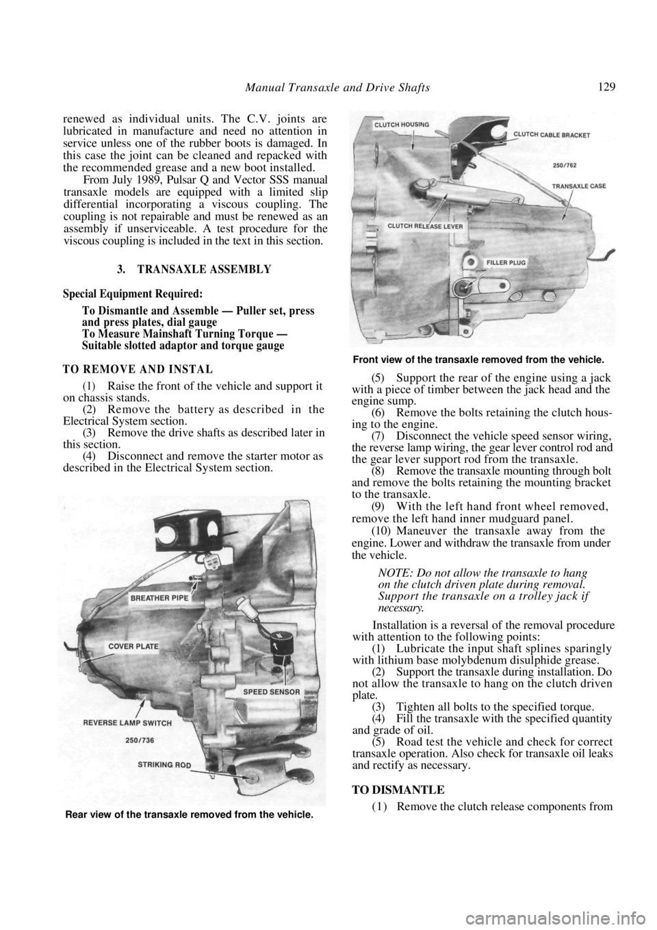
Front view of the transaxle removed from the vehicle.
(5) Support the rear of the engine using a jack
with a piece of timber between the jack head and the
engine sump.
(6) Remove the bolts retaining the clutch hous-
ing to the engine. (7) Disconnect the vehicle speed sensor wiring,
the reverse lamp wiring, the gear lever control rod and
the gear lever support rod from the transaxle. (8) Remove the transaxle mounting through bolt
and remove the bolts retaining the mounting bracket
to the transaxle.
(9) With the left hand front wheel removed,
remove the left hand inner mudguard panel. (10) Maneuver the transaxle away from the
engine. Lower and withdraw the transaxle from under
the vehicle.
NOTE: Do not allow the transaxle to hang
on the clutch driven plate during removal.
Support the transaxle on a trolley jack if
necessary.
Installation is a reversal of the removal procedure
with attention to the following points:
(1) Lubricate the input shaft splines sparingly
with lithium base molybdenum disulphide grease. (2) Support the transaxle during installation. Do
not allow the transaxle to hang on the clutch driven
plate. (3) Tighten all bolts to the specified torque.
(4) Fill the transaxle with the specified quantity
and grade of oil. (5) Road test the vehicle and check for correct
transaxle operation. Also ch eck for transaxle oil leaks
and rectify as necessary.
TO DISMANTLE
(1) Remove the clutch release components from Rear view of the transaxle removed from the vehicle.
Page 137 of 238
Manual Transaxle and Drive Shafts 137
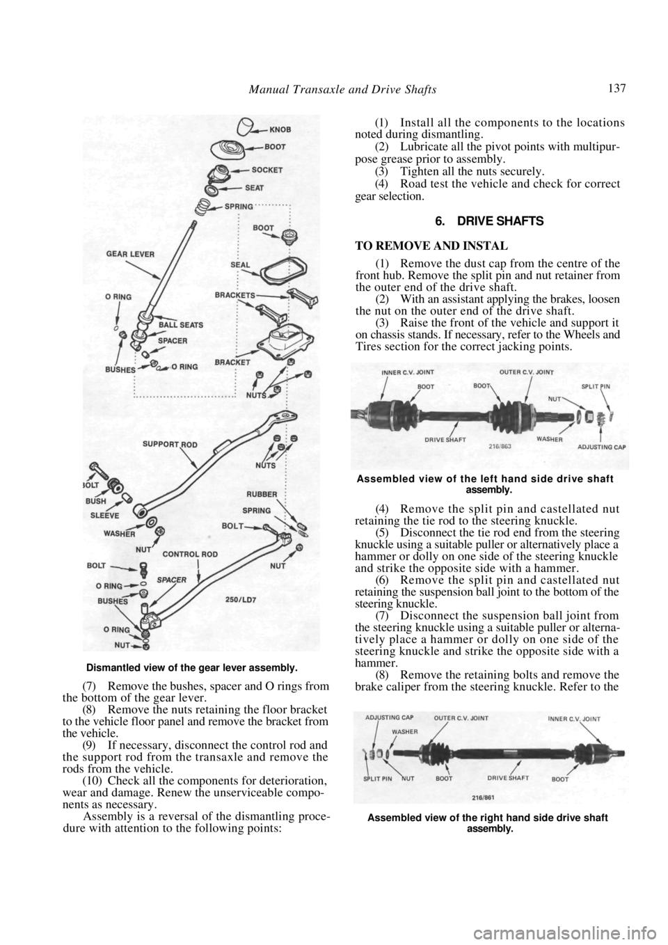
Dismantled view of the gear lever assembly.
(7) Remove the bushes, spacer and O rings from
the bottom of the gear lever.
(8) Remove the nuts retaining the floor bracket
to the vehicle floor panel and remove the bracket from
the vehicle. (9) If necessary, disconnect the control rod and
the support rod from the transaxle and remove the
rods from the vehicle. (10) Check all the components for deterioration,
wear and damage. Renew the unserviceable compo-
nents as necessary. Assembly is a reversal of the dismantling proce-
dure with attention to the following points:
(1) Install all the components to the locations
noted during dismantling.
(2) Lubricate all the pivot points with multipur-
pose grease prior to assembly. (3) Tighten all the nuts securely.
(4) Road test the vehicle and check for correct
gear selection.
6. DRIVE SHAFTS
TO REMOVE AND INSTAL
(1) Remove the dust cap from the centre of the
front hub. Remove the split pin and nut retainer from
the outer end of the drive shaft. (2) With an assistant applying the brakes, loosen
the nut on the outer end of the drive shaft.
(3) Raise the front of the vehicle and support it
on chassis stands. If necessary, refer to the Wheels and
Tires section for the correct jacking points.
Assembled view of the left hand side drive shaft
assembly.
(4) Remove the split pin and castellated nut
retaining the tie rod to the steering knuckle. (5) Disconnect the tie rod end from the steering
knuckle using a suitable puller or alternatively place a
hammer or dolly on one side of the steering knuckle
and strike the opposite side with a hammer.
(6) Remove the split pin and castellated nut
retaining the suspension ball joint to the bottom of the
steering knuckle. (7) Disconnect the suspension ball joint from
the steering knuckle using a suitable puller or alterna-
tively place a hammer or dolly on one side of the
steering knuckle and strike the opposite side with a
hammer. (8) Remove the retaining bolts and remove the
brake caliper from the stee ring knuckle. Refer to the
Assembled view of the right hand side drive shaft
assembly.
Page 143 of 238
Automatic Transaxle 143
facing towards the radiator support panel at the front
of the vehicle.
The neutral safety switch allows electrical current
to pass to the starter circ uit only when the selector
lever is in the Park or Neutral position. The switch is
adjustable but non-repairable.
TO TEST
(1) Disconnect the neutral safety switch wiring
connector.
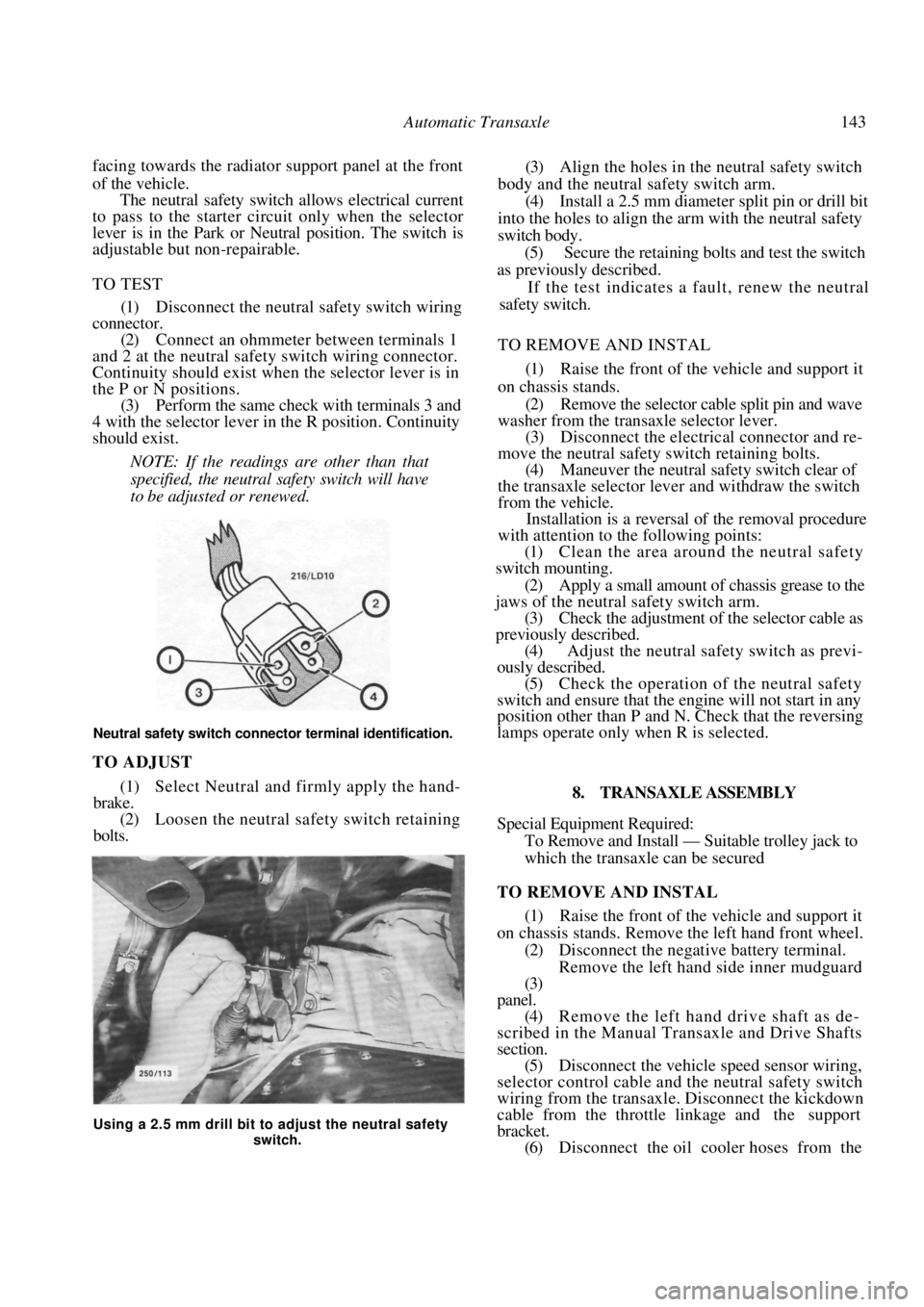
(2) Connect an ohmmeter between terminals 1
and 2 at the neutral safety switch wiring connector.
Continuity should exist when the selector lever is in
the P or N positions. (3) Perform the same check with terminals 3 and
4 with the selector lever in the R position. Continuity
should exist.
NOTE: If the readings are other than that
specified, the neutral safety switch will have
to be adjusted or renewed.
Neutral safety switch connector terminal identification.
TO ADJUST
(1) Select Neutral and firmly apply the hand-
brake. (2) Loosen the neutral safety switch retaining
bolts.
(3) Align the holes in the neutral safety switch
body and the neutral safety switch arm. (4) Install a 2.5 mm diameter split pin or drill bit
into the holes to align the arm with the neutral safety
switch body. (5) Secure the retaining bolts and test the switch
as previously described.
If the test indicates a fault, renew the neutral
safety switch.
TO REMOVE AND INSTAL
(1) Raise the front of the vehicle and support it
on chassis stands. (2) Remove the selector cable split pin and wave
washer from the transaxle selector lever.
(3) Disconnect the electric al connector and re-
move the neutral safety switch retaining bolts. (4) Maneuver the neutral safety switch clear of
the transaxle selector lever and withdraw the switch
from the vehicle. Installation is a reversal of the removal procedure
with attention to the following points:
(1) Clean the area around the neutral safety
switch mounting.
(2) Apply a small amount of chassis grease to the
jaws of the neutral safety switch arm. (3) Check the adjustment of the selector cable as
previously described. (4) Adjust the neutral safety switch as previ-
ously described.
(5) Check the operation of the neutral safety
switch and ensure that the engine will not start in any
position other than P and N. Check that the reversing
lamps operate only when R is selected.
8. TRANSAXLE ASSEMBLY
Special Equipment Required:
To Remove and Install — Suitable trolley jack to
which the transaxle can be secured
TO REMOVE AND INSTAL
(1) Raise the front of the vehicle and support it
on chassis stands. Remove the left hand front wheel.
(2) Disconnect the negative battery terminal. Remove the left hand side inner mudguard
(3)
panel.
(4) Remove the left hand drive shaft as de-
scribed in the Manual Tran saxle and Drive Shafts
section. (5) Disconnect the vehicle speed sensor wiring,
selector control cable and the neutral safety switch
wiring from the transaxle. Disconnect the kickdown
cable from the throttle linkage and the support
bracket. (6) Disconnect the oil cooler hoses from the
Using a 2.5 mm drill bit to adjust the neutral safety
switch.
Page 144 of 238
144 Automatic Transaxle
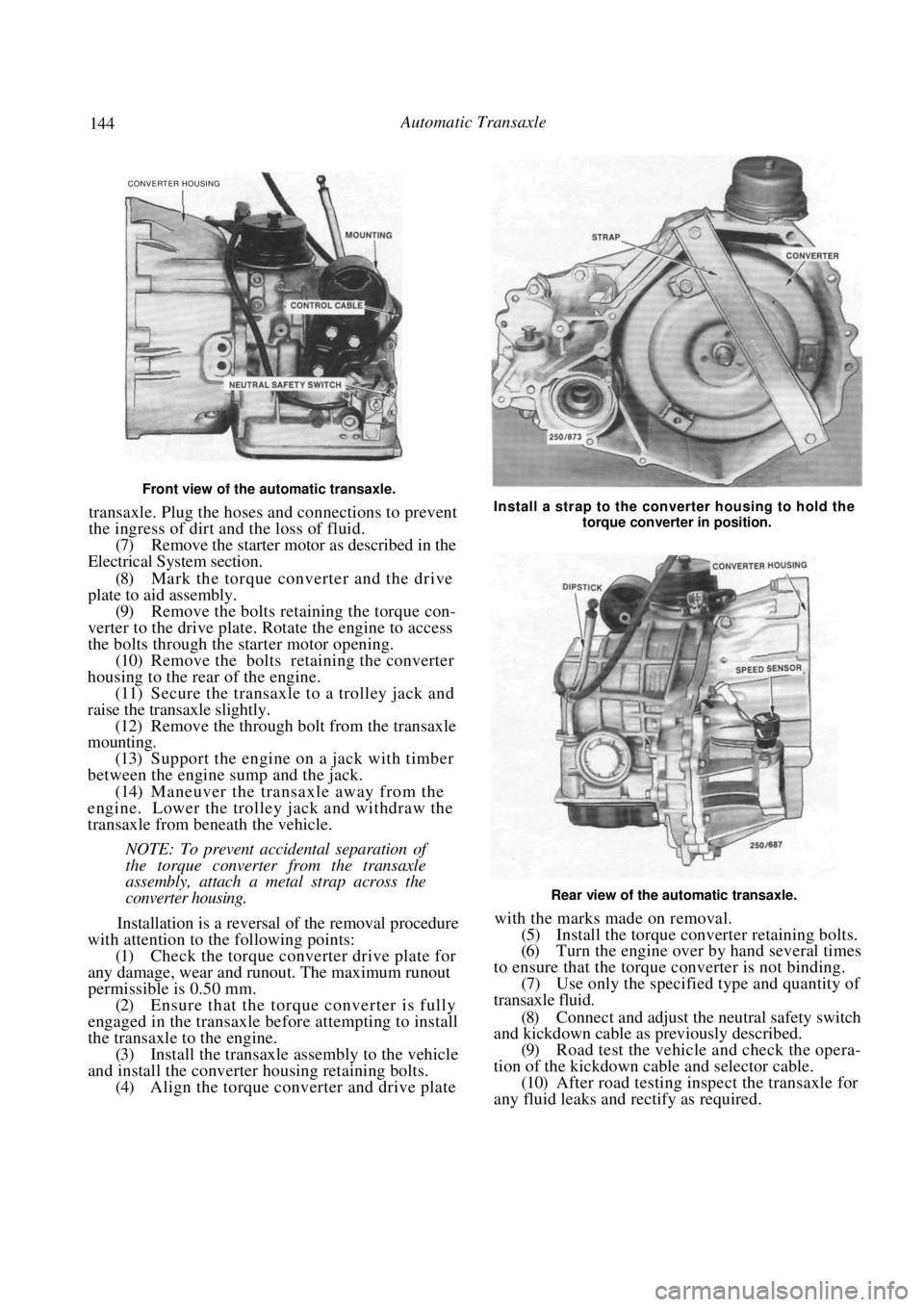
Front view of the automatic transaxle.
transaxle. Plug the hoses and connections to prevent
the ingress of dirt and the loss of fluid.
(7) Remove the starter motor as described in the
Electrical System section.
(8) Mark the torque converter and the drive
plate to aid assembly.
(9) Remove the bolts retaining the torque con-
verter to the drive plate. Rotate the engine to access
the bolts through the starter motor opening. (10) Remove the bolts retaining the converter
housing to the rear of the engine. (11) Secure the transaxle to a trolley jack and
raise the transaxle slightly. (12) Remove the through bolt from the transaxle
mounting.
(13) Support the engine on a jack with timber
between the engine sump and the jack. (14) Maneuver the transaxle away from the
engine. Lower the trolley jack and withdraw the
transaxle from beneath the vehicle.
NOTE: To prevent accidental separation of
the torque converter from the transaxle
assembly, attach a metal strap across the
converter housing.
Installation is a reversal of the removal procedure
with attention to the following points:
(1) Check the torque converter drive plate for
any damage, wear and runout. The maximum runout
permissible is 0.50 mm.
(2) Ensure that the torque converter is fully
engaged in the transaxle be fore attempting to install
the transaxle to the engine. (3) Install the transaxle assembly to the vehicle
and install the converter housing retaining bolts. (4) Align the torque converter and drive plate
Install a strap to the converter housing to hold the
torque converter in position.
Rear view of the automatic transaxle.
with the marks made on removal.
(5) Install the torque converter retaining bolts.
(6) Turn the engine over by hand several times
to ensure that the torque converter is not binding. (7) Use only the specified type and quantity of
transaxle fluid.
(8) Connect and adjust the neutral safety switch
and kickdown cable as previously described.
(9) Road test the vehicle and check the opera-
tion of the kickdown cable and selector cable. (10) After road testing inspect the transaxle for
any fluid leaks and rectify as required.
CONVERTER HOUSING
Page 150 of 238
150 Steering — Part 2
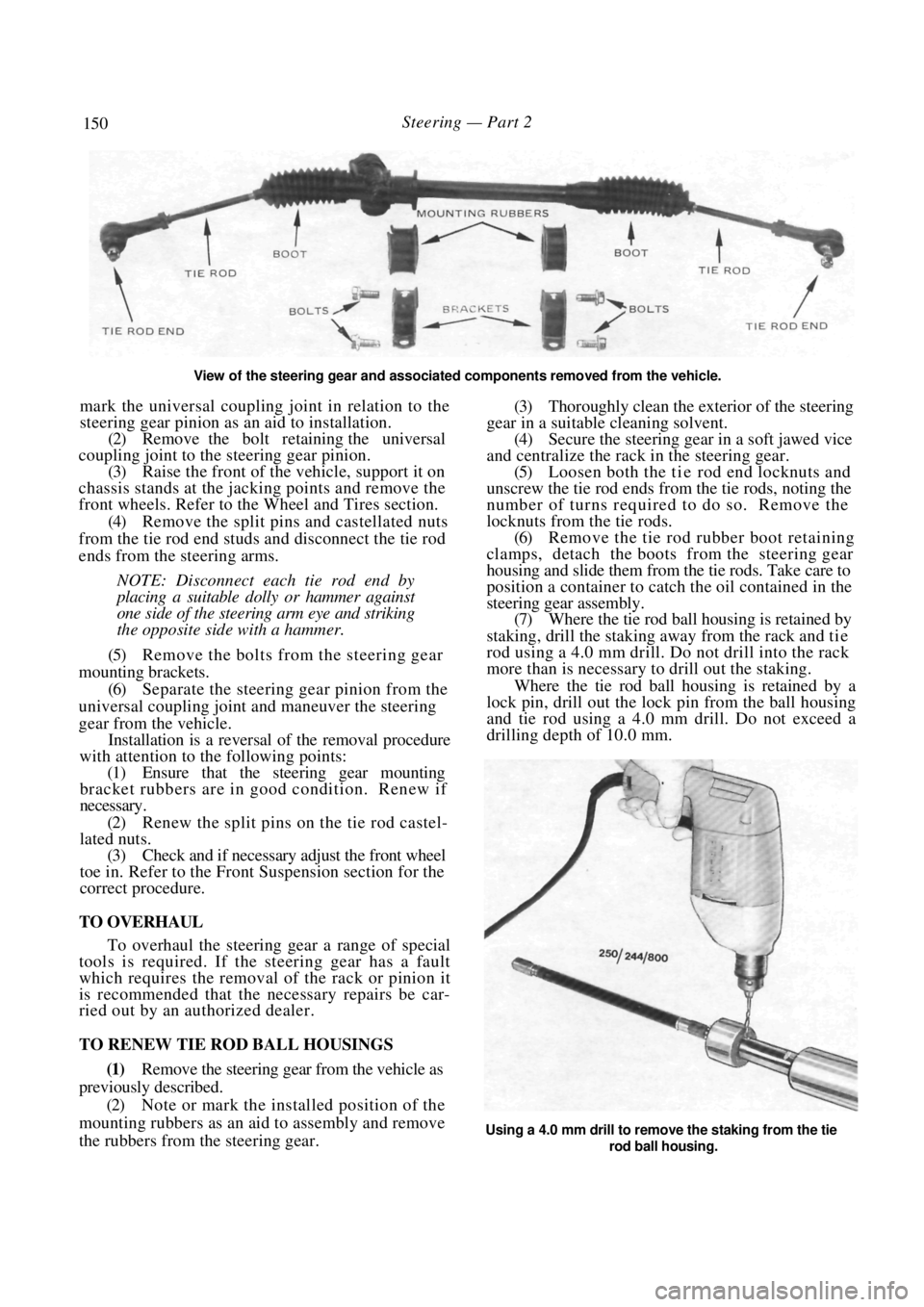
View of the steering gear and associated components removed from the vehicle.
mark the universal coupling joint in relation to the
steering gear pinion as an aid to installation.
(2) Remove the bolt retaining the universal
coupling joint to the steering gear pinion. (3) Raise the front of the vehicle, support it on
chassis stands at the jack ing points and remove the
front wheels. Refer to the Wheel and Tires section.
(4) Remove the split pins and castellated nuts
from the tie rod end studs and disconnect the tie rod
ends from the steering arms.
NOTE: Disconnect each tie rod end by
placing a suitable dolly or hammer against
one side of the steer ing arm eye and striking
the opposite side with a hammer.
(5) Remove the bolts from the steering gear
mounting brackets. (6) Separate the steering gear pinion from the
universal coupling joint and maneuver the steering
gear from the vehicle. Installation is a reversal of the removal procedure
with attention to the following points:
(1) Ensure that the steering gear mounting
bracket rubbers are in good condition. Renew if
necessary.
(2) Renew the split pins on the tie rod castel-
lated nuts.
(3) Check and if necessary adjust the front wheel
toe in. Refer to the Front Suspension section for the
correct procedure.
TO OVERHAUL
To overhaul the steering gear a range of special
tools is required. If the steering gear has a fault
which requires the removal of the rack or pinion it
is recommended that the necessary repairs be car-
ried out by an authorized dealer.
TO RENEW TIE ROD BALL HOUSINGS
(1) Remove the steering gear from the vehicle as
previously described.
(2) Note or mark the installed position of the
mounting rubbers as an aid to assembly and remove
the rubbers from the steering gear.
(3) Thoroughly clean the exterior of the steering
gear in a suitable cleaning solvent.
(4) Secure the steering gear in a soft jawed vice
and centralize the rack in the steering gear. (5) Loosen both the ti e rod end locknuts and
unscrew the tie rod ends from the tie rods, noting the
number of turns required to do so. Remove the
locknuts from the tie rods. (6) Remove the tie rod rubber boot retaining
clamps, detach the boot s from the steering gear
housing and slide them from the tie rods. Take care to
position a container to catch the oil contained in the
steering gear assembly. (7) Where the tie rod ball housing is retained by
staking, drill the staking away from the rack and t i e
rod using a 4.0 mm drill. Do not drill into the rack
more than is necessary to drill out the staking.
Where the tie rod ball housing is retained by a
lock pin, drill out the lock pin from the ball housing
and tie rod using a 4.0 mm drill. Do not exceed a
drilling depth of 10.0 mm.
Using a 4.0 mm drill to remove the staking from the tie
rod ball housing.