run flat NISSAN PULSAR 1987 Workshop Manual
[x] Cancel search | Manufacturer: NISSAN, Model Year: 1987, Model line: PULSAR, Model: NISSAN PULSAR 1987Pages: 238, PDF Size: 28.91 MB
Page 12 of 238
12 General Information
Damaged threads can be repaired using a die nut
on studs and bolts, and a tap on nuts and threaded
holes in castings. If the threads of a threaded hole are
damaged beyond repair, it will be necessary to drill
and tap the hole to a larger size. Alternatively, a
Helicoil insert can be used to Testore the hole to the
original thread size.
STUDS
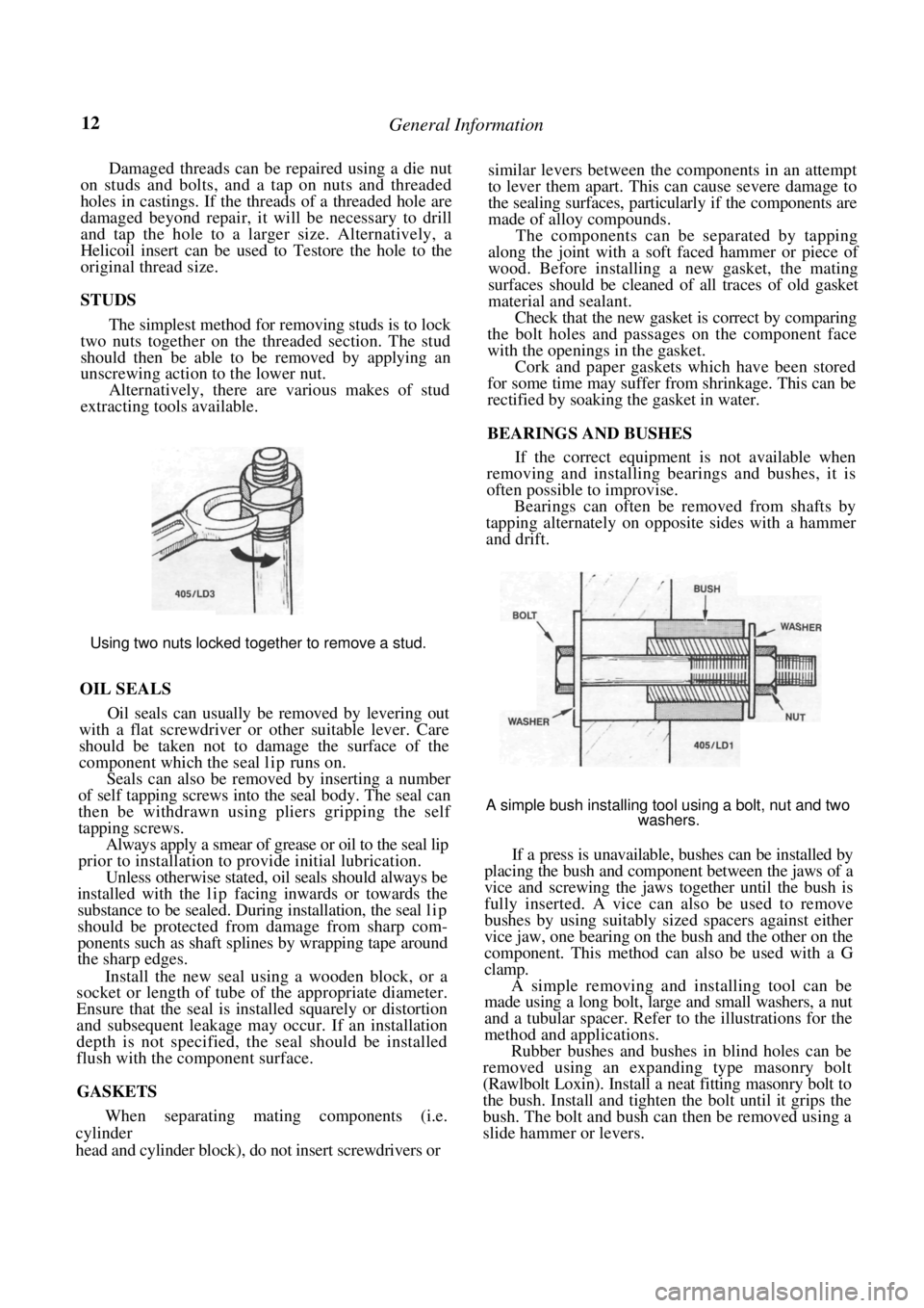
The simplest method for removing studs is to lock
two nuts together on the threaded section. The stud
should then be able to be removed by applying an
unscrewing action to the lower nut.
Alternatively, there are various makes of stud
extracting tools available.
Using two nuts locked together to remove a stud.
OIL SEALS
Oil seals can usually be removed by levering out
with a flat screwdriver or other suitable lever. Care
should be taken not to damage the surface of the
component which the seal lip runs on.
Seals can also be removed by inserting a number
of self tapping screws into the seal body. The seal can
then be withdrawn using pliers gripping the self
tapping screws.
Always apply a smear of grease or oil to the seal lip
prior to installation to provide initial lubrication.
Unless otherwise stated, oil seals should always be
installed with the lip facing inwards or towards the
substance to be sealed. Duri ng installation, the seal l i p
should be protected from damage from sharp com-
ponents such as shaft splines by wrapping tape around
the sharp edges.
Install the new seal using a wooden block, or a
socket or length of tube of the appropriate diameter.
Ensure that the seal is installed squarely or distortion
and subsequent leakage may occur. If an installation
depth is not specified, th e seal should be installed
flush with the component surface.
GASKETS
When separating mating components (i.e.
cylinder
head and cylinder block), do not insert screwdrivers or
similar levers between the components in an attempt
to lever them apart. This can cause severe damage to
the sealing surfaces, particularly if the components are
made of alloy compounds.
The components can be separated by tapping
along the joint with a soft faced hammer or piece of
wood. Before installing a new gasket, the mating
surfaces should be cleaned of all traces of old gasket
material and sealant.
Check that the new gasket is correct by comparing
the bolt holes and passages on the component face
with the openings in the gasket.
Cork and paper gaskets which have been stored
for some time may suffer from shrinkage. This can be
rectified by soaking the gasket in water.
BEARINGS AND BUSHES
If the correct equipment is not available when
removing and installing bearings and bushes, it is
often possible to improvise.
Bearings can often be removed from shafts by
tapping alternately on opposite sides with a hammer
and drift.
A simple bush installing tool using a bolt, nut and two
washers.
If a press is unavailable, bushes can be installed by
placing the bush and component between the jaws of a
vice and screwing the jaws together until the bush is
fully inserted. A vice can also be used to remove
bushes by using suitably sized spacers against either
vice jaw, one bearing on the bush and the other on the
component. This method can also be used with a G
clamp.
A simple removing and installing tool can be
made using a long bolt, large and small washers, a nut
and a tubular spacer. Refer to the illustrations for the
method and applications.
Rubber bushes and bushes in blind holes can be
removed using an expanding type masonry bolt
(Rawlbolt Loxin). Install a neat fitting masonry bolt to
the bush. Install and tighten the bolt until it grips the
bush. The bolt and bush can then be removed using a
slide hammer or levers.
Page 22 of 238
22 Wheels and Tires
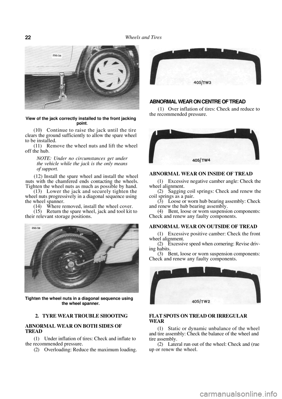
View of the jack correctly installed to the front jacking point
.
(10) Continue to raise the jack until the tire
clears the ground sufficiently to allow the spare wheel
to be installed.
(11) Remove the wheel nuts and lift the wheel
off the hub.
NOTE: Under no circumstances get under
the vehicle while the jack is the only means
of support.
(12) Install the spare wh eel and install the wheel
nuts with the chamfered e nds contacting the wheels.
Tighten the wheel nuts as much as possible by hand.
(13) Lower the jack and securely tighten the
wheel nuts progressively in a diagonal sequence using
the wheel spanner. (14) Where removed, install the wheel cover.
(15) Return the spare wheel, jack and tool kit to
their relevant storage positions.
ABNORMAL WEAR ON CENTRE OF TREAD
(1) Over inflation of tires: Check and reduce to
the recommended pressure.
ABNORMAL WEAR ON INSIDE OF TREAD
(1) Excessive negative camber angle: Check the
wheel alignment. (2) Sagging coil springs: Check and renew the
coil springs as a pair. (3) Loose or worn hub bearing assembly: Check
and renew the hub bearing assembly. (4) Bent, loose or worn suspension components:
Check and renew any faulty components.
ABNORMAL WEAR ON OUTSIDE OF TREAD
(1) Excessive positive camber: Check the front
wheel alignment.
(2) Excessive speed when cornering: Revise driv-
ing habits. (3) Bent, loose or worn suspension components:
Check and renew any faulty components.
2. TYRE WEAR TROUBLE SHOOTING
ABNORMAL WEAR ON BOTH SIDES OF
TREAD
(1) Under inflation of tires: Check and inflate to
the recommended pressure.
(2) Overloading: Reduce the maximum loading. FLAT SPOTS ON TREAD OR IRREGULAR
WEAR
(1)
Static or dynamic unbalance of the wheel
and tire assembly: Check the balance of the wheel and
tire assembly. (2) Lateral run out of the wheel: Check and (rue
up or renew the wheel.
Tighten the wheel nuts in a diagonal sequence using
the wheel spanner.
Page 28 of 238
Engine Tune-up
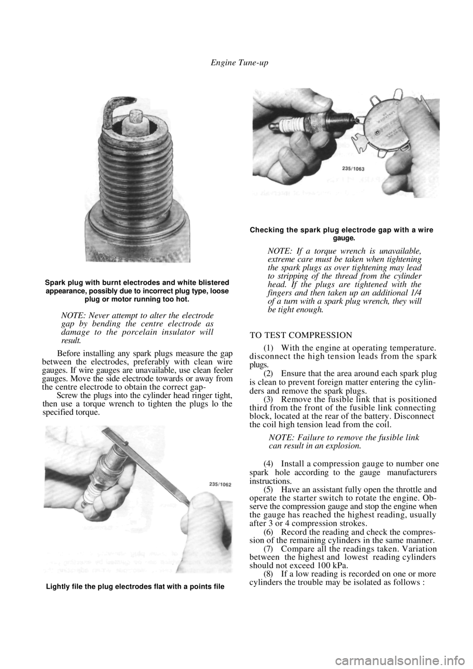
Spark plug with burnt electrodes and white blistered
appearance, possibly due to incorrect plug type, loose
plug or motor running too hot.
NOTE: Never attempt to alter the electrode
gap by bending the centre electrode as
damage to the porcelain insulator will
result.
Before installing any spark plugs measure the gap
between the electrodes, pref erably with clean wire
gauges. If wire gauges are una vailable, use clean feeler
gauges. Move the side electrode towards or away from
the centre electrode to obtain the correct gap-
Screw the plugs into the cylinder head ringer tight,
then use a torque wrench to tighten the plugs lo the
specified torque.
Checking the spark plug electrode gap with a wire
gauge.
NOTE: If a torque wrench is unavailable,
extreme care must be taken when tightening
the spark plugs as over tightening may lead
to stripping of the thread from the cylinder
head. If the plugs are tightened with the
fingers and then taken up an additional 1/4
of a turn with a spark plug wrench, they will
be tight enough.
TO TEST COMPRESSION
(1) With the engine at operating temperature.
disconnect the high tension leads from the spark
plugs.
(2) Ensure that the area around each spark plug
is clean to prevent foreign matter entering the cylin-
ders and remove the spark plugs. (3) Remove the fusible link that is positioned
third from the front of th e fusible link connecting
block, located at the rear of the battery. Disconnect
the coil high tension lead from the coil.
NOTE: Failure to remove the fusible link
can result in an explosion.
(4) Install a compression gauge to number one
spark hole according to the gauge manufacturers
instructions. (5) Have an assistant fully open the throttle and
operate the starter switch to rotate the engine. Ob-
serve the compression gauge and stop the engine when
the gauge has reached the highest reading, usually
after 3 or 4 compression strokes.
(6) Record the reading a nd check the compres-
sion of the remaining cylinders in the same manner.
(7) Compare all the readings taken. Variation
between the highest and lowest reading cylinders
should not exceed 100 kPa. (8) If a low reading is recorded on one or more
cylinders the trouble may be isolated as follows :
Lightly file the plug electrodes flat with a points file
Page 33 of 238
Roadside Trouble Shooting
(5) Place the vent caps loosely over the cell
apertures.
(6) Connect one end of the red jumper lead to
the positive ( + ) battery terminal of the booster
battery and the other end of the red lead to the
positive (+) battery terminal of the discharged bat-
tery.
NOTE: The battery emits hydrogen gas
which is explosive. Do not expose the battery
to naked /lames or sparks.
Do not lean over the battery when con-
necting the jumper leads.
Do not allow the ends of the jumper leads
to touch one another or any part of the
engine.
(7) Connect one end of the black juniper lead to
the negative (-) battery terminal of the booster
battery and the other end of the black lead to a good
earthing point on the engine of the vehicle with the
discharged battery.
NOTE: Do not connect the jumper lead
directly to the negative (-) battery terminal
of the discharged battery.
(8) Start the engine on the vehicle with the
booster battery and run the engine at a moderate
speed. (9) Start the engine on the vehicle with the
discharged battery.
(10) If possible, leave the engines of both vehi-
cles running for 10 minutes.
(11) Disconnect the jumper leads in the reverse
order of the sequence in which they were connected.
2. TO CHECK IGNITION AND ELECTRICAL SYSTEM
(1) Switch on the ignition and check for warning
lamp illumination on the dashboard. (2) Operate the starter and check that the starter
rotates the engine at a steady speed.
(3) Switch on the headlamps and check for good
light intensity. Should the lamps not illum inate or the starter
motor not turn the engine, carry out the following
steps:
(a) Remove the battery terminals and clean both
terminals and posts. Connect the terminals and where
applicable tighten firmly but not excessively.
(b) Check that the earth lead from the battery to
the engine or body frame is not broken and that the
connections are clean and secure. . (c) Check that the lead from the battery to the
starter motor or starter solenoid is intact and has a
clean and secure connection.
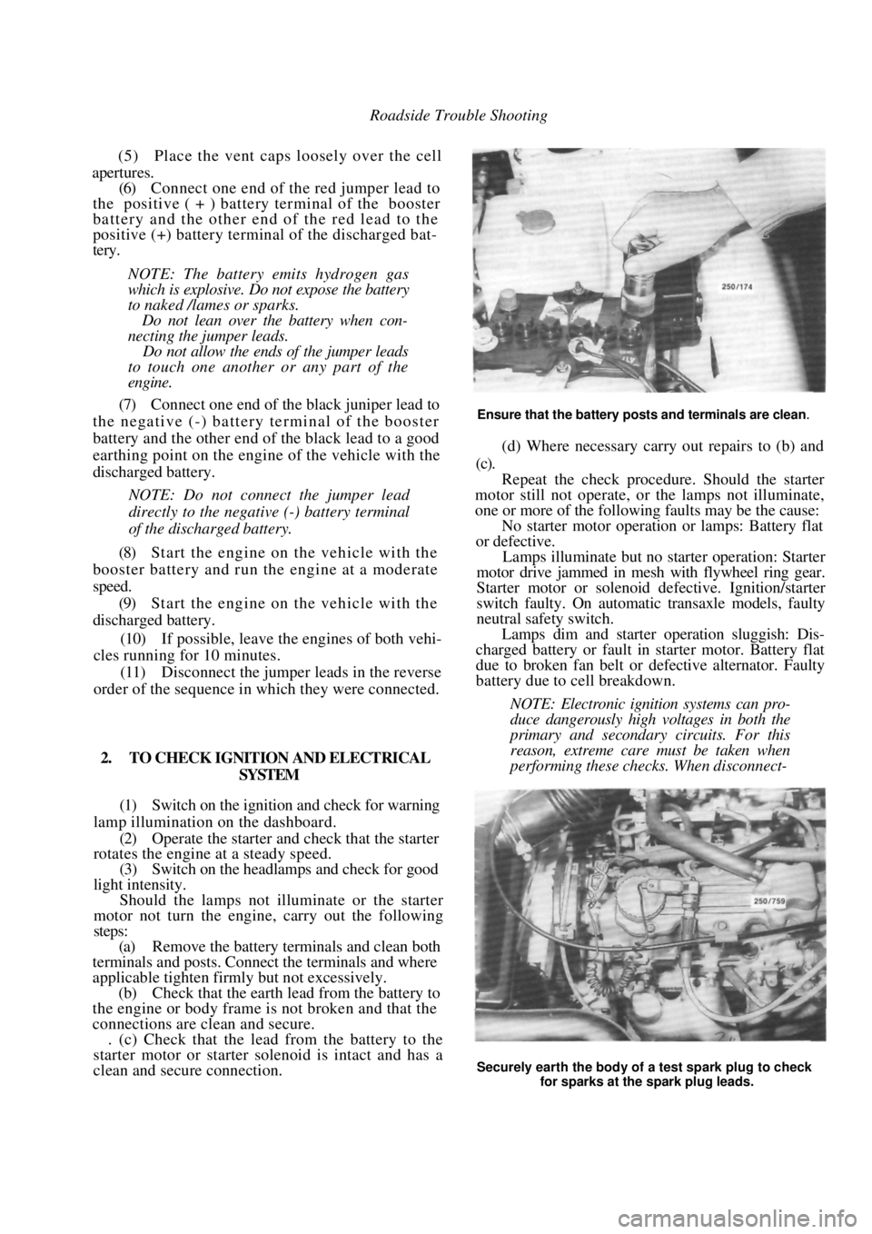
Ensure that the battery posts and terminals are clean.
(d) Where necessary carry out repairs to (b) and
(c).
Repeat the check procedur e. Should the starter
motor still not operate, or the lamps not illuminate,
one or more of the following faults may be the cause:
No starter motor operation or lamps: Battery flat
or defective.
Lamps illuminate but no starter operation: Starter
motor drive jammed in mesh with flywheel ring gear.
Starter motor or solenoid defective. Ignition/starter
switch faulty. On automatic transaxle models, faulty
neutral safety switch.
Lamps dim and starter operation sluggish: Dis-
charged battery or fault in starter motor. Battery flat
due to broken fan belt or de fective alternator. Faulty
battery due to cell breakdown.
NOTE: Electronic ignition systems can pro-
duce dangerously high voltages in both the
primary and secondary circuits. For this
reason, extreme care must be taken when
performing these checks. When disconnect-
Securely earth the body of a test spark plug to check
for sparks at the spark plug leads.
Page 180 of 238
180 Brakes
the caliper body. Plug the brake hose to prevent the
loss of fluid and the ingress of dirt. Remove and
discard the sealing washers.
(3) Remove the guide bolts and slide the caliper
body from the anchor plate and pad assembly. (4) Remove the piston dust cover retaining clip.
Remove and discard the dust cover.
BRAKEPAD BRAKE PAD
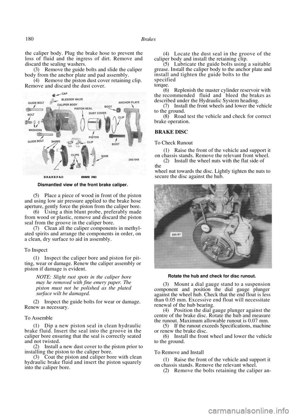
Dismantled view of the front brake caliper.
(5) Place a piece of wood in front of the piston
and using low air pressure applied to the brake hose
aperture, gently force the piston from the caliper bore.
(6) Using a thin blunt probe, preferably made
from wood or plastic, remove and discard the piston
seal from the groove in the caliper bore. (7) Clean all the caliper components in methyl-
ated spirits and arrange the components in order, on
a clean, dry surface to aid in assembly.
To Inspect
(1) Inspect the caliper bore and piston for pit-
ting, wear or damage. Renew the caliper assembly or
piston if damage is evident.
NOTE: Slight rust spots in the caliper bore
may he removed with fine emery paper. The
piston must not be polished as the plated
surface wilt be damaged.
(2) Inspect the guide bolts for wear or damage.
Renew as necessary.
To Assemble
(1) Dip a new piston seal in clean hydraulic
brake fluid. Insert the seal into the groove in the
caliper bore ensuring that the seal is correctly seated
and not twisted.
(2) Install a new dust cover to the piston prior to
installing the piston to the caliper bore. (3) Coat the piston and caliper bore with clean
hydraulic brake fluid and insert the piston squarely
into the caliper bore.
(4) Locate the dust seal in the groove of the
caliper body and install the retaining clip.
(5) Lubricate the guide bolts using a suitable
grease. Install the caliper body to the anchor plate and
install and tighten the guide bolts to the
specified
torque. (6) Replenish the master cylinder reservoir with
the recommended fluid and bleed the brakes as
described under the Hydr aulic System heading.
(7) Install the front wheels and lower the vehicle
to the ground. (8) Road test the vehicle and check for correct
brake operation.
BRAKE DISC
To Check Runout
(1) Raise the front of the vehicle and support it
on chassis stands. Remove the relevant front wheel. (2) Install the wheel nuts with the flat side of
the
wheel nut towards the disc. Lightly tighten the nuts to
secure the disc against the hub.
Rotate the hub and check for disc runout.
(3) Mount a dial gauge stand to a suspension
component and position the dial gauge plunger
against the wheel hub. Check that the end float is less
than 0.05 mm. Excessive e nd float will necessitate
renewal of the hub bearing. (4) Position the dial gauge plunger against the
centre of the brake disc. Ro tate the hub and measure
the runout. Maximum allowable runout is 0.07 mm. (5) If the runout exceeds Specifications, machine
or renew the brake disc. (6) Install the fron t wheel and lower the vehicle
to the ground.
To Remove and Install
(1) Raise the front of the vehicle and support it
on chassis stands. Remove the relevant wheel. (2) Remove the bolts retaining the caliper an-