sensor NISSAN PULSAR 1987 Workshop Manual
[x] Cancel search | Manufacturer: NISSAN, Model Year: 1987, Model line: PULSAR, Model: NISSAN PULSAR 1987Pages: 238, PDF Size: 28.91 MB
Page 7 of 238
VEHICLE IDENTIFICATION AND GENERAL SPECIFICATIONS
1. VEHICLE IDENTIFICATION
When purchasing spare parts or when
registering
or insuring a vehicle, it may be necessary to quote
various vehicle identification codes. The location of
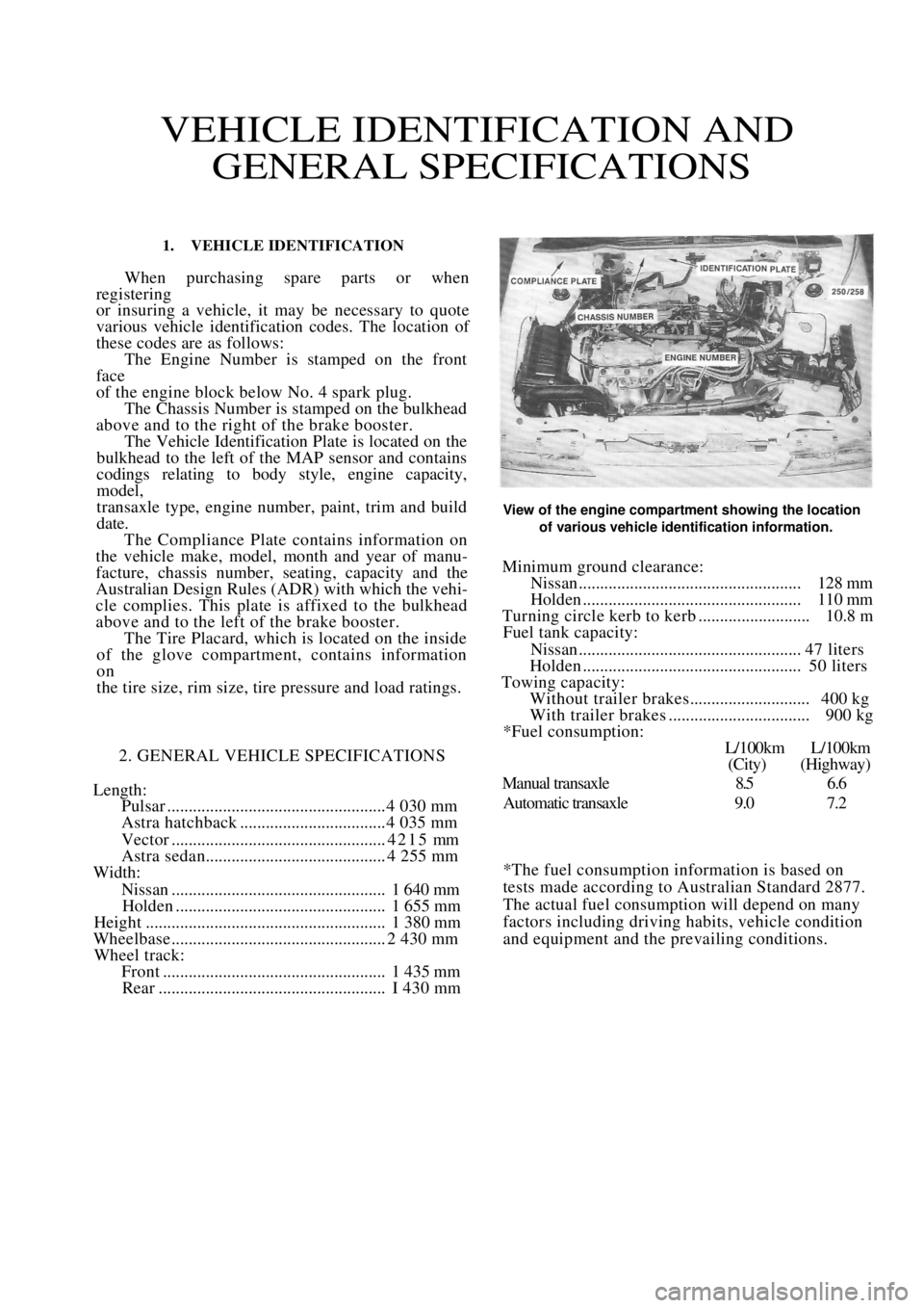
these codes are as follows: The Engine Number is stamped on the front
face
of the engine block below No. 4 spark plug. The Chassis Number is stamped on the bulkhead
above and to the right of the brake booster. The Vehicle Identification Plate is located on the
bulkhead to the left of the MAP sensor and contains
codings relating to body style, engine capacity,
model,
transaxle type, engine number, paint, trim and build
date. The Compliance Plate contains information on
the vehicle make, model, month and year of manu-
facture, chassis number, seating, capacity and the
Australian Design Rules (ADR) with which the vehi-
cle complies. This plate is affixed to the bulkhead
above and to the left of the brake booster. The Tire Placard, which is located on the inside
of the glove compartment, contains information
on
the tire size, rim size, tire pressure and load ratings.
2. GENERAL VEHICLE SPECIFICATIONS
Length:
Pulsar ................................................... 4 030 mm
Astra hatchback .................................. 4 035 mm
Vector ..................................................4215 mm
Astra sedan.......................................... 4 255 mm
Width:
Nissan.................................................. 1 640 mm
Holden ................................................. 1 655 mm
Height ........................................................ 1 380 mm
Wheelbase .................................................. 2 430 mm
Wheel track:
Front .................................................... 1 435 mm
Rear ..................................................... I 430 mm
View of the engine compartment showing the location
of various vehicle identification information.
Minimum ground clearance:
Nissan.................................................... 128 mm
Holden ................................................... 110 mm
Turning circle kerb to kerb .......................... 10.8 m
Fuel tank capacity:
Nissan.................................................... 47 liters
Holden ................................................... 50 liters
Towing capacity:
Without trailer brakes............................ 400 kg
With trailer brakes ................................. 900 kg
*Fuel consumption:
L/100km L/100km
(City) (Highway)
Manual transaxle 8.5 6.6
Automatic transaxle 9.0 7.2
*The fuel consumption information is based on
tests made according to Australian Standard 2877.
The actual fuel consumption will depend on many
factors including driving habits, vehicle condition
and equipment and the prevailing conditions.
Page 35 of 238
Roadside Trouble Shooting 35
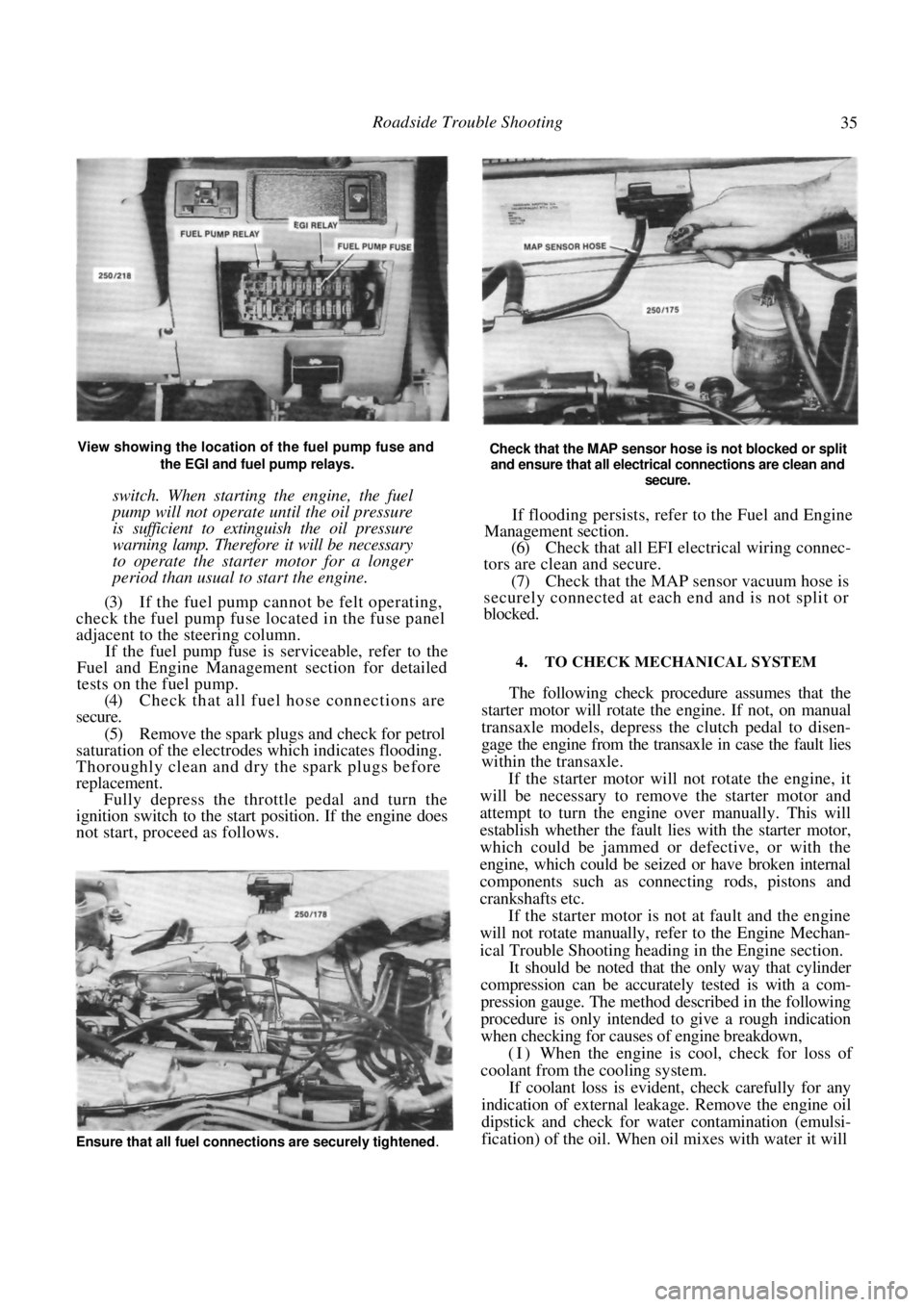
View showing the location of the fuel pump fuse and the EGI and fuel pump relays.
switch. When starting the engine, the fuel
pump will not operate until the oil pressure
is sufficient to extinguish the oil pressure
warning lamp. Therefore it will be necessary
to operate the starter motor for a longer
period than usual to start the engine.
(3) If the fuel pump cannot be felt operating,
check the fuel pump fuse located in the fuse panel
adjacent to the steering column.
If the fuel pump fuse is serviceable, refer to the
Fuel and Engine Management section for detailed
tests on the fuel pump.
(4) Check that all fuel hose connections are
secure.
(5) Remove the spark plugs and check for petrol
saturation of the electrodes which indicates flooding.
Thoroughly clean and dry the spark plugs before
replacement. Fully depress the throttle pedal and turn the
ignition switch to the start position. If the engine does
not start, proceed as follows.
Check that the MAP sensor hose is not blocked or split
and ensure that all electrical connections are clean and
secure.
If flooding persists, refer to the Fuel and Engine
Management section.
(6) Check that all EFI electrical wiring connec-
tors are clean and secure.
(7) Check that the MAP sensor vacuum hose is
securely connected at each end and is not split or
blocked.
4. TO CHECK MECHANICAL SYSTEM
The following check procedure assumes that the
starter motor will rotate the engine. If not, on manual
transaxle models, depress the clutch pedal to disen-
gage the engine from the tr ansaxle in case the fault lies
within the transaxle.
If the starter motor will not rotate the engine, it
will be necessary to remove the starter motor and
attempt to turn the engine over manually. This will
establish whether the fault lies with the starter motor,
which could be jammed or defective, or with the
engine, which could be seized or have broken internal
components such as connecting rods, pistons and
crankshafts etc.
If the starter motor is not at fault and the engine
will not rotate manually, refer to the Engine Mechan-
ical Trouble Shooting heading in the Engine section.
It should be noted that the only way that cylinder
compression can be accurately tested is with a com-
pression gauge. The method described in the following
procedure is only intended to give a rough indication
when checking for causes of engine breakdown,
(I) When the engine is cool, check for loss of
coolant from the cooling system.
If coolant loss is evident, check carefully for any
indication of external leakage. Remove the engine oil
dipstick and check for wate r contamination (emulsi-
fication) of the oil. When oil mixes with water it will
Ensure that all fuel connections are securely tightened.
Page 42 of 238

42 Engine
The cylinder block is a cast iron alloy, deep skirt
design and the crankshaft is supported in the cylinder
block by five precision insert replaceable main bear-
ings. Crankshaft end float is controlled by the flanged
centre main bearing. Connecting rods are I section
forgings equipped with precision insert replaceable big
end bearings. The gudgeon pins are an interference fit
in the connecting rod and a floating fit in the piston.
The cast aluminum pistons are equipped with
two compression rings and one oil control ring.
The twin rotor, involute gear oil pump is mounted
directly to the front face of the cylinder block. The
inner rotor is internally driven by the crankshaft. The
oil pump pressure relief valve is not adjustable, and
consists of a plunger and spring mounted in the oil
pump body.
The pump draws oil through a screen in the sump
and delivers it, via a full flow replaceable oil filter, to
the oil gallery from where it is distributed to the
hydraulic tappets, camshaft and crankshaft bearings
and to the overhead rocker and valve mechanism.
3. ENGINE AND TRANSAXLE ASSEMBLY
Special Equipment Required:
To Remove and Instill — Suitable lifting tackle,
extra long chassis stands, suitable trolley
TO REMOVE
NOTE: Due to the high residual pressure
within the fuel system, it will be necessary to
depressurize the system before removing any
fuel supply components. Refer to the Fuel
and Engine Management section for the
correct procedure.
(1) Disconnect the negative battery terminal.
(2) Mark around the bonnet hinges with a soft
lead pencil Co facilitate correct installation. With the
aid of an assistant, remove the bonnet retaining bolts
and remove the bonnet from the vehicle.
(3) Drain the engine and transaxle lubricant.
(4) Open the coolant drain tap located on the
lower radiator pipe and drain the coolant. (5) Loosen the hose clips and disconnect the
heater hoses from the heater pipes at the bulkhead.
NOTE: Do not use excessive force to remove
the heater hoses from the heater pipes or the
heater core will become dislodged from the
heater unit. If necessary, cut the heater
hoses from the pipes using a sharp knife.
(6) Loosen the hose clamps and disconnect the
radiator hoses from the engine assembly. (7) Disconnect the positive lead from the bat-
tery. (8) On 1.8 liter models, disconnect the air inlet
duct.
(9) On 1.6 liter models, remove the air cleaner
assembly. Refer to the Fuel and Engine Management
section if necessary. (10) Disconnect the throttle cable from the throt-
tle body and from the camshaft housing top cover
bracket, if applicable. (11) Disconnect the fuel supply and return hoses.
Mark the hoses as an aid to installation. (12) Suitably mark and disconnect the charcoal
canister hoses. (13) Disconnect the injector wires from the injec-
tors. On 1.6 liter models, slide the wiring out from the
throttle body. (14) Disconnect the wiring fr om the throttle po-
sition sensor (TPS), idle air control (IAC) valve,
oxygen (O
2) sensor wire, coolant temperature sensor,
coolant sender and on 1.8 liter models, the manifold
air temperature (MAT) sensor. (15) Disconnect the wiring connector adjacent to
the top heater hose, the wiring from the alternator and
the two earth wires from underneath the cylinder head
bolts. (16) Lay the wiring loom over on the passenger
side of the engine compar tment, clear of the work
area.
(17) On manual transaxle models, loosen the
clutch cable adjusting nuts and remove the cable
through the slot in the lever. Remove the clutch cable
bracket from the transaxle after removing the retain-
ing bolts and place the cable to one side.
(18) Disconnect the wiring from the starter mo-
tor, speedometer sender and on manual transaxle
models, the reverse lamp switch wiring.
(19) If applicable, disconnect the power steering
lines from the pump and drain the fluid into a
container. Suitably plug the lines and the pump to
prevent the entry of dirt.
(20) On automatic transaxle models, disconnect
the selector cable and bracket from the transaxle
assembly.
Disconnect the transaxle oil cooler lines from the
transaxle. Plug the lines and fittings to prevent the
entry of dirt etc.
(21) Loosen the front wheel nuts, raise the front
of the vehicle and support it on extra long chassis
stands. Ensure that the vehicle is high enough to allow
removal of the engine from underneath. (22) Remove the front wheels and the engine
splash guards from the vehicle.
(23) On manual transaxle models, remove the
stay rod and control rod bolts and nuts and disconnect
the rods from the transaxle.
(24) Remove the lower control arm to steering
knuckle ball joint nuts and separate the ball joints
from the steering knuckle by holding a dolly or a
hammer against one side of the steering knuckle and
hitting the other side with a hammer. The taper on the
ball joint will release fr om the steering knuckle.
(25) Pull the steering knuckles outward swiftly to
Page 45 of 238
Engine 45
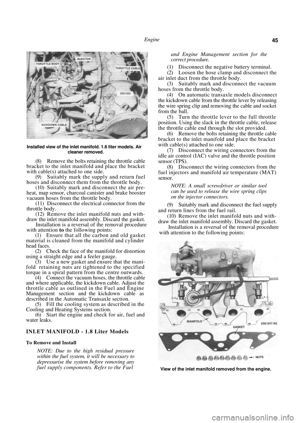
Installed view of the inlet manifold. 1.6 liter models. Air
cleaner removed.
(8) Remove the bolts retaining the throttle cable
bracket to the inlet manifold and place the bracket
with cable(s) attached to one side.
(9) Suitably mark the supply and return fuel
hoses and disconnect them from the throttle body.
(10) Suitably mark and disconnect the air pre-
heat, map sensor, charcoal canister and brake booster
vacuum hoses from the throttle body. (11) Disconnect the electrical connector from the
throttle body. (12) Remove the inlet manifold nuts and with-
draw the inlet manifold assembly. Discard the gasket. Installation is a reversal of the removal procedure
with attention to the following points:
(1) Ensure that all the carbon and old gasket
material is cleaned from the manifold and cylinder
head faces. (2) Check the face of the manifold for distortion
using a straight edge and a feeler gauge. (3) Use a new gasket and ensure that the mani-
fold retaining nuts are tightened to the specified
torque in a spiral pattern from the centre outwards. (4) Connect the vacuum hoses, the throttle cable
and where applicable, the kickdown cable. Adjust the
throttle cable as outlined in the Fuel and Engine
Management section and the kickdown cable as
described in the Automatic Transaxle section. (5) Fill the cooling system as described in the
Cooling and Heating Systems section. (6) Start the engine and check for air, fuel and
water leaks.
INLET MANIFOLD - 1.8 Liter Models
To Remove and Install
NOTE: Due to the high residual pressure
within the fuel system, it will be necessary to
depressurise the system before removing any
fuel supply components. Refer to the Fuel
and Engine Management section for the
correct procedure.
(1) Disconnect the negative battery terminal.
(2) Loosen the hose clamp and disconnect the
air inlet duct from the throttle body. (3) Suitably mark and disconnect the vacuum
hoses from the throttle body. (4) On automatic transaxle models disconnect
the kickdown cable from the throttle lever by releasing
the wire spring clip and re moving the cable and socket
from the ball. (5) Turn the throttle lever to the full throttle
position. Using the slack in the throttle cable, release
the throttle cable end thr ough the slot provided.
(6) Remove the bolts retaining the throttle cable
bracket to the inlet manifold and place the bracket
with cable(s) attached to one side. (7) Disconnect the wiring connectors from the
idle air control (IAC) valve and the throttle position
sensor (TPS).
(8) Disconnect the wiring connectors from the
fuel injectors and manifold air temperature (MAT)
sensor.
NOTE: A small screwdriver or similar tool
can be used to release the wire spring clips
on the injector connectors.
(9) Suitably mark and disconnect the fuel supply
and return lines from the fuel rail. (10) Remove the inlet manifold nuts and with-
draw the inlet manifold assembly. Discard the gasket. Installation is a reversal of the removal procedure
with attention to the following points:
View of the inlet manifold removed from the engine.
Page 46 of 238
46 Engine
(1) Ensure that all carbon and old gasket mate-
rial is cleaned from the manifold and cylinder head
faces. (2) Check the face of the manifold for distortion
using a straight edge and a feeler gauge. (3) Use a new gasket and ensure that the mani-
fold retaining nuts are tightened to the specified
torque in a spiral pattern from the centre outwards. (4) Adjust the throttle cabl e as described in the
Fuel and Engine Management section and the kick-
down cable as described in the Automatic Transaxle
section.
(5) Start the engine and check for air, fuel and
water leaks.
EXHAUST MANIFOLD
To Remove and Install
(1) Bring the engine to operating temperature
and remove the oxygen sensor.
(2) Disconnect the negative battery terminal.
(3) On 1.6 liter models, remove the air cleaner
nuts, disconnect the vacuum hose and withdraw the
air cleaner from the vehicle. (4) Remove the front exhaust pipe flange mount-
ing nuts and separate the exhaust pipe from the
manifold. (5) Remove the heat shield retaining bolts and
withdraw the heat shield from the exhaust manifold. (6) Remove the exhaust manifold to cylinder
head retaining nuts and remove the manifold from the
engine. Discard the manifold gasket. Installation is a reversal of the removal procedure
with attention to the following points:
(1) Ensure that all carbon is cleaned from the
manifold and cylinder head mating surfaces. (2) Check the face of the manifold for distortion
using a straight edge and feeler gauges. (3) Use new gaskets on assembly.
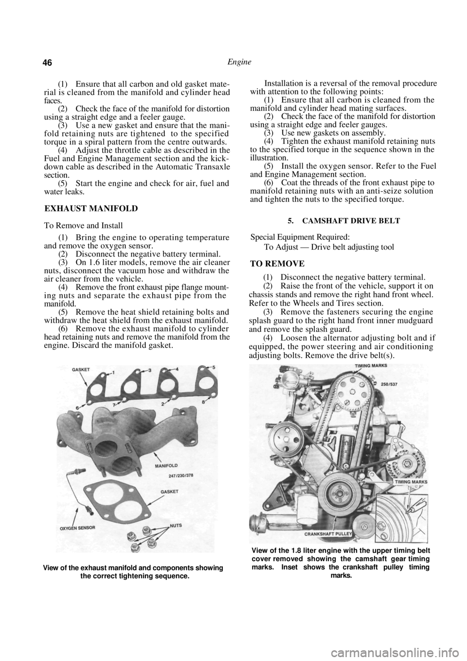
(4) Tighten the exhaust manifold retaining nuts
to the specified torque in the sequence shown in the
illustration. (5) Install the oxygen sensor. Refer to the Fuel
and Engine Management section. (6) Coat the threads of the front exhaust pipe to
manifold retaining nuts with an anti-seize solution
and tighten the nuts to the specified torque.
5. CAMSHAFT DRIVE BELT
Special Equipment Required:
To Adjust — Drive belt adjusting tool
TO REMOVE
(1) Disconnect the negative battery terminal.
(2) Raise the front of the vehicle, support it on
chassis stands and remove the right hand front wheel.
Refer to the Wheels and Tires section. (3) Remove the fasteners securing the engine
splash guard to the right hand front inner mudguard
and remove the splash guard. (4) Loosen the alternator adjusting bolt and if
equipped, the power steering and air conditioning
adjusting bolts. Remove the drive belt(s).
View of the exhaust manifold and components showing
the correct tightening sequence.
View of the 1.8 liter engine with the upper timing belt
cover removed showing the camshaft gear timing
marks. Inset shows the crankshaft pulley timing
marks.
Page 50 of 238

50 Engine
(4) Ensure that the tappet assemblies are full of
clean engine oil and insert the tappets in their
respective bores in the cylinde r head. Install the thrust
pads to the top of each valve assembly ensuring that
they are returned to their original location.
(5) Coat the contact surfaces of the rocker arms
with molybdenum disulphide grease and install the
rocker arms to their origin al locations on the cylinder
head. (6) Clean the mating surfaces of the camshaft
housing and cylinder head. Apply a bead of Loctite
515 to the cylinder head and camshaft housing mating
surfaces. Take care that no sea lant is forced into the
oil passages and install the camshaft housing to the
cylinder head.
(7) Install new cylinder head bolts and lubricate
the bolts and washers with oil.
(8) Apply an initial torque to the cylinder head
bolts of 25 Nm in the corr ect sequence as shown in
the illustration under the Cylinder Head heading.
Further tighten the head bolts in the correct sequence,
in three separate 60 degree stages. Refer to Specifica-
tions. (9) Install the bolts securing the camshaft
drive
belt inner cover to the camshaft housing. (10) Install the camshaft timing gear to the cam-
shaft ensuring that it is correctly located. Tighten the
camshaft timing gear retain ing boll to the specified
torque. (11) Install and adjust the camshaft drive belt as
described under the previous heading. (12) Install the distributor. Refer to the Fuel and
Engine Management section.
(13) Connect the lower radiat or hose and fill the
cooling system with the required coolant. Refer to the
Cooling and Heating Systems section if necessary. (14) Start and run the engine until normal oper-
ating temperature is attained and tighten the cylinder
head bolts another 30-50 degrees in the correct
sequence, ensuring that the tension does not exceed
135 Nm.
TO RENEW CAMSHAFT OIL SEAL,
CAMSHAFT INSTALLED
(1) Remove the camshaft drive belt from the
camshaft timing gear as described under the previous
heading.
(2) Remove the camshaft housing top cover
retaining bolts, remove the cover and discard the
gasket.
(3) Use an open end spanner to hold the cam-
shaft between the inlet and exhaust lobes of number
four cylinder and remove the camshaft timing gear
retaining bolt and the camshaft timing gear. (4) With a pointed drift, tap a small hole in the
front face of the oil seal. Insert a self tapping screw in
the hole and using a pair of pliers, pull on the screw
to remove the oil seal from the housing.
(5) Clean the seal recess and the camshaft sea!
running surface. (6) Lubricate the lip of a new oil seal with engine
oil and slide the seal over the camshaft. Ensure that
the lip of the seal faces to wards the inside of the
camshaft housing. Tap evenly around the edges of the
seal until it is fully seated in the camshaft housing.
(7) Install the camshaft timing gear to the cam-
shaft, ensuring that it is co rrectly located. Tighten the
camshaft timing gear retain ing bolt to the specified
torque. Do not allow the camshaft to rotate while
tightening the bolt. (8) Install and adjust the drive belt as described
under the previous heading. Ensure that the timing
marks are aligned. (9) Install the camshaft hou sing top cover using a
new gasket. Tighten the retaining bolts to the specified
torque.
7. CYLINDER HEAD
Special Equipment Required:
To Dismantle and Assemble — Valve spring com-
pressor
To Inspect — Dial gauge and straight edge
To Install — Drive belt adjusting tool
TO REMOVE AND INSTAL
NOTE: Due to the high residua! pressure
within the fuel system, it will be necessary to
depressurize the system before removing any
fuel supply components. Refer to the Fuel
and Engine Management section for the
correct procedure.
Allow the engine to cool prior to the
removal of the cylinder head to prevent
possible distortion of the cylinder head.
(1) Disconnect the negative battery terminal and
remove the nuts securing the earth wires to the
cylinder head bolts.
(2) Remove the camshaft drive belt as previ-
ously described.
(3) Disconnect the lower radiator hose and drain
the cooling system. Refer to the Cooling and Heating
Systems section if necessary. (4) Remove the alternator adjusting bracket
mounting bolt and insulating washers from the inlet
manifold. Loosen the adjusting bolt at the alternator
and slide the bracket away from the cylinder head. (5) Disconnect the upper radiator hose, coolant
by-pass hose and the heater hose from the thermostat
housing and on 1.6 liter m odels, the coolant hoses
from the inlet manifold. (6) Disconnect the electrica l connectors from the
throttle body, fuel injectors, coil, distributor and on
1.8 liter models, the MAT sensor. (7) Disconnect the oxygen sensor wiring connec-
tor and remove the wiring connectors from the
Page 51 of 238
Engine 51
coolant temperature sensor and temperature sender
switch located in the thermostat housing.
(8) Remove the bolt securing the wiring clamp
to the rear of the manifold and maneuver the wiring
away from the cylinder head and the inlet manifold.
(9) Disconnect the throttle cable and on auto-
matic transaxle models, the kickdown cable from the
throttle body linkage. (10) Remove the bolls securing the throttle cable
bracket to the inlet manifold and place the bracket
and cable(s) to one side.
(11) Mark the fuel supply and return hoses to
ensure correct installation and disconnect the hoses
from the fuel rail or throttle body. Plug the hoses to
prevent the loss of fuel or the entry of dirt. (12) Mark the vacuum hoses connected to the
inlet manifold and throttle body to ensure correct
installation and disconnect the hoses. (13) Remove the nuts securing the engine pipe to
the exhaust manifold and separate the pipe from the
manifold. (14) Remove the oxygen sensor from the exhaust
manifold. Refer to the Fuel and Engine Management
section if necessary. (15) Remove the distributor and coil as described
in the Fuel and Engine Management section. (16) Disconnect the engine breather hoses from
the camshaft housing and cams haft housing top cover.
(17) Remove the bolts retaining the top cover to
the camshaft housing and remove the top cover. (18) Using an open end spanner, hold the cam-
shaft between the inlet and exhaust lobes of number
four cylinder and remove the camshaft timing gear
retaining bolt and the camshaft timing gear.
(19) Remove the bolts securing the camshaft
drive belt inner cover to the camshaft housing. (20) Loosen the cylinder head bolts in the reverse
order of the tightening sequence, backing off each bolt
a quarter turn then half a turn at a time until the bolts
are loose.
NOTE: Do not loosen the head bolts while
the engine is warm as distortion of the
cylinder head could result.
(21) Remove the cylinder head bolts and lift the
camshaft housing from the cylinder head. (22) Remove the cylinder head and gasket from
the cylinder block. Installation is a reversal of the removal procedure
with attention to the following points:
(1) Thoroughly clean the gasket surfaces of the
cylinder head, cylinder block and camshaft housing
and check all mating surfaces with a straight edge.
Ensure that all the oilways are clean and free of any
foreign material and lightly oil all operating parts with
engine oil.
(2) Install new gaskets throughout during
assem-
bly.
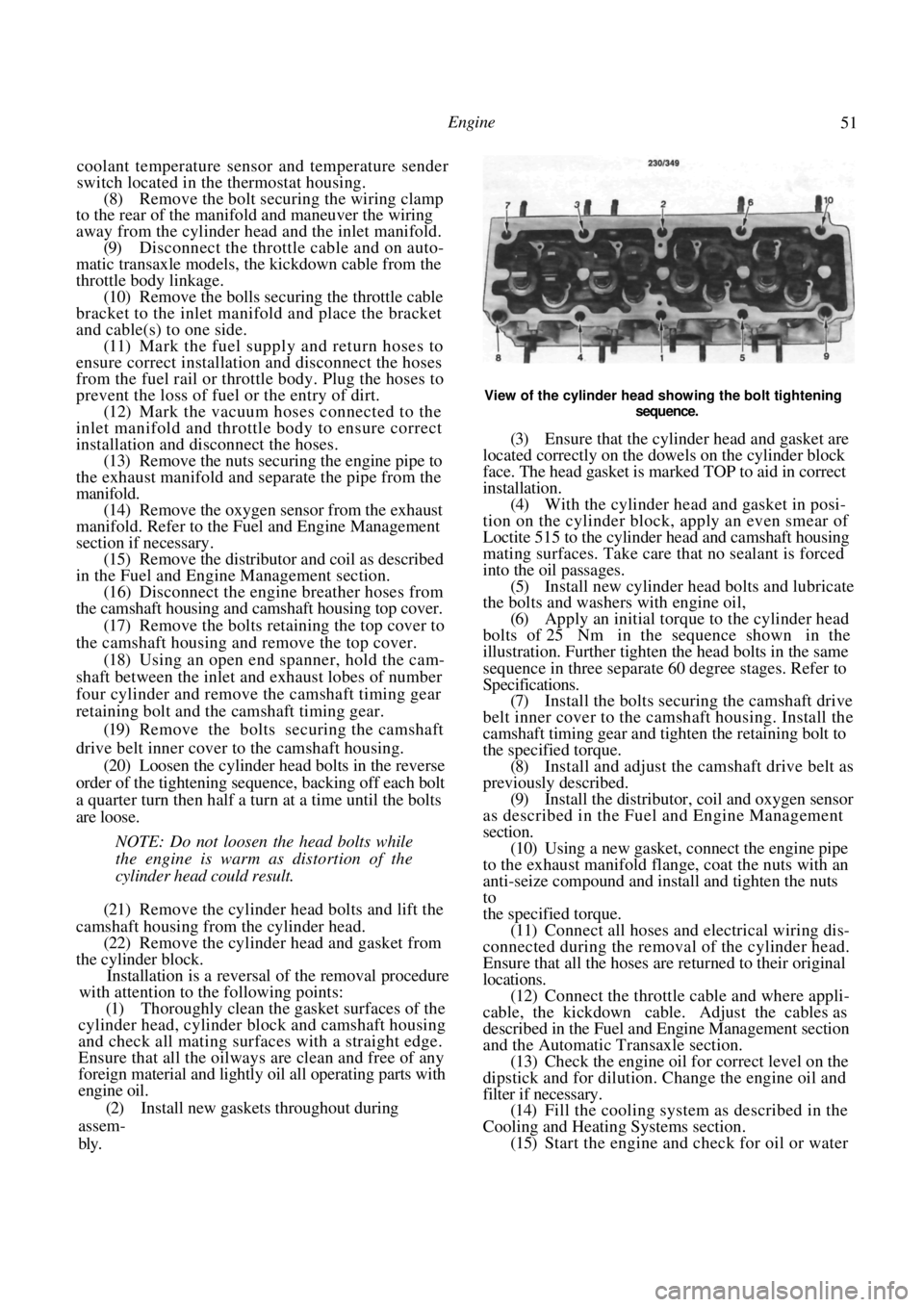
View of the cylinder head showing the bolt tightening
sequence.
(3) Ensure that the cylinde r head and gasket are
located correctly on the dowels on the cylinder block
face. The head gasket is marked TOP to aid in correct
installation. (4) With the cylinder head and gasket in posi-
tion on the cylinder block, apply an even smear of
Loctite 515 to the cylinder head and camshaft housing
mating surfaces. Take care that no sealant is forced
into the oil passages. (5) Install new cylinder head bolts and lubricate
the bolts and washers with engine oil,
(6) Apply an initial torque to the cylinder head
bolts of 25 Nm in the sequence shown in the
illustration. Further tighten the head bolts in the same
sequence in three separate 60 degree stages. Refer to
Specifications. (7) Install the bolts secur ing the camshaft drive
belt inner cover to the camshaft housing. Install the
camshaft timing gear and tighten the retaining bolt to
the specified torque. (8) Install and adjust the camshaft drive belt as
previously described. (9) Install the distributor, coil and oxygen sensor
as described in the Fuel and Engine Management
section.
(10) Using a new gasket, connect the engine pipe
to the exhaust manifold flange, coat the nuts with an
anti-seize compound and install and tighten the nuts
to
the specified torque. (11) Connect all hoses and electrical wiring dis-
connected during the removal of the cylinder head.
Ensure that all the hoses are returned to their original
locations. (12) Connect the throttle cable and where appli-
cable, the kickdown cable. Adjust the cables as
described in the Fuel and Engine Management section
and the Automatic Transaxle section. (13) Check the engine oil fo r correct level on the
dipstick and for dilution. Change the engine oil and
filter if necessary. (14) Fill the cooling system as described in the
Cooling and Heating Systems section. (15) Start the engine and check for oil or water
Page 70 of 238
70 Cooling and Heating Systems
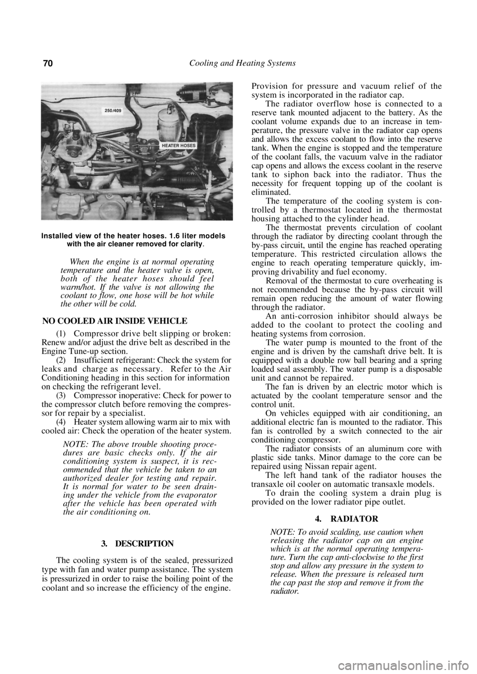
Installed view of the heater hoses. 1.6 liter models with the air cleaner removed for clarity
.
When the engine is at normal operating
temperature and the heater valve is open,
both of the heater hoses should feel
warm/hot. If the valve is not allowing the
coolant to flow, one hose will be hot while
the other will be cold.
NO COOLED AIR INSIDE VEHICLE
(1) Compressor drive belt slipping or broken:
Renew and/or adjust the drive belt as described in the
Engine Tune-up section.
(2) Insufficient refrigerant: Check the system for
leaks and charge as necessary. Refer to the Air
Conditioning heading in th is section for information
on checking the refrigerant level. (3) Compressor inoperative: Check for power to
the compressor clutch before removing the compres-
sor for repair by a specialist. (4) Heater system allowing warm air to mix with
cooled air: Check the operation of the heater system.
NOTE: The above trouble shooting proce-
dures are basic checks only. If the air
conditioning system is suspect, it is rec-
ommended that the vehicle be taken to an
authorized dealer for testing and repair.
It is normal for water to be seen drain-
ing under the vehicle from the evaporator
after the vehicle has been operated with
the air conditioning on.
3. DESCRIPTION
The cooling system is of the sealed, pressurized
type with fan and water pump assistance. The system
is pressurized in order to raise the boiling point of the
coolant and so increase the efficiency of the engine.
Provision for pressure a nd vacuum relief of the
system is incorporated in the radiator cap.
The radiator overflow hose is connected to a
reserve tank mounted adjacent to the battery. As the
coolant volume expands due to an increase in tem-
perature, the pressure valve in the radiator cap opens
and allows the excess coolant to flow into the reserve
tank. When the engine is stopped and the temperature
of the coolant falls, the vacuum valve in the radiator
cap opens and allows the excess coolant in the reserve
tank to siphon back into the radiator. Thus the
necessity for frequent topping up of the coolant is
eliminated.
The temperature of the cooling system is con-
trolled by a thermostat located in the thermostat
housing attached to the cylinder head.
The thermostat prevents circulation of coolant
through the radiator by directing coolant through the
by-pass circuit, until the engine has reached operating
temperature. This restricted circulation allows the
engine to reach operating temperature quickly, im-
proving drivability and fuel economy.
Removal of the thermostat to cure overheating is
not recommended because th e by-pass circuit will
remain open reducing the amount of water flowing
through the radiator.
An anti-corrosion inhibitor should always be
added to the coolant to protect the cooling and
heating systems from corrosion.
The water pump is mounted to the front of the
engine and is driven by the camshaft drive belt. It is
equipped with a double row ball bearing and a spring
loaded seal assembly. The water pump is a disposable
unit and cannot be repaired.
The fan is driven by an electric motor which is
actuated by the coolant temperature sensor and the
control unit.
On vehicles equipped with air conditioning, an
additional electric fan is m ounted to the radiator. This
fan is controlled by a sw itch connected to the air
conditioning compressor.
The radiator consists of an aluminum core with
plastic side tanks. Minor damage to the core can be
repaired using Nissan repair agent.
The left hand tank of the radiator houses the
transaxle oil cooler on automatic transaxle models.
To drain the cooling system a drain plug is
provided on the lower radiator pipe outlet.
4. RADIATOR
NOTE: To avoid scalding, use caution when
releasing the radiator cap on an engine
which is at the normal operating tempera-
ture. Turn the cap anti-clockwise to the first
stop and allow any pressure in the system to
release. When the pressure is released turn
the cap past the stop and remove it from the
radiator.
Page 73 of 238
Cooling and Heating Systems 73
(1) Renew all hoses that show signs of cracking
or perishing.
(2) Before finally tightening the hose clips, en-
sure that the hoses are push ed fully onto the radiator
and are not kinked. (3) On automatic transaxle models, ensure that
the oil cooler hoses are correctly installed to the
radiator and show no signs of leakage. Check and top
up the automatic transaxle fluid as necessary.
5. COOLING FAN
The radiator cooling fan is controlled by the
electronic control unit, and on vehicles with air
conditioning, the condenser fan relay. On vehicles
with air conditioning there are two cooling fans, one
is larger than the other. The large fan is for the
radiator and the smaller fan provides extra cooling
when the air conditioning is activated. Each fan is
controlled by a separate system.
TO TEST COOLING FAN AND SYSTEM
(1) With the cooling system cold and the air
conditioning, if applicable, switched off, switch the
ignition On and confirm that the cooling fan is
stationary.
NOTE: Leave the ignition On for all tests
unless otherwise stated.
(2) In the above test, if the cooling fan rotates,
proceed as follows:
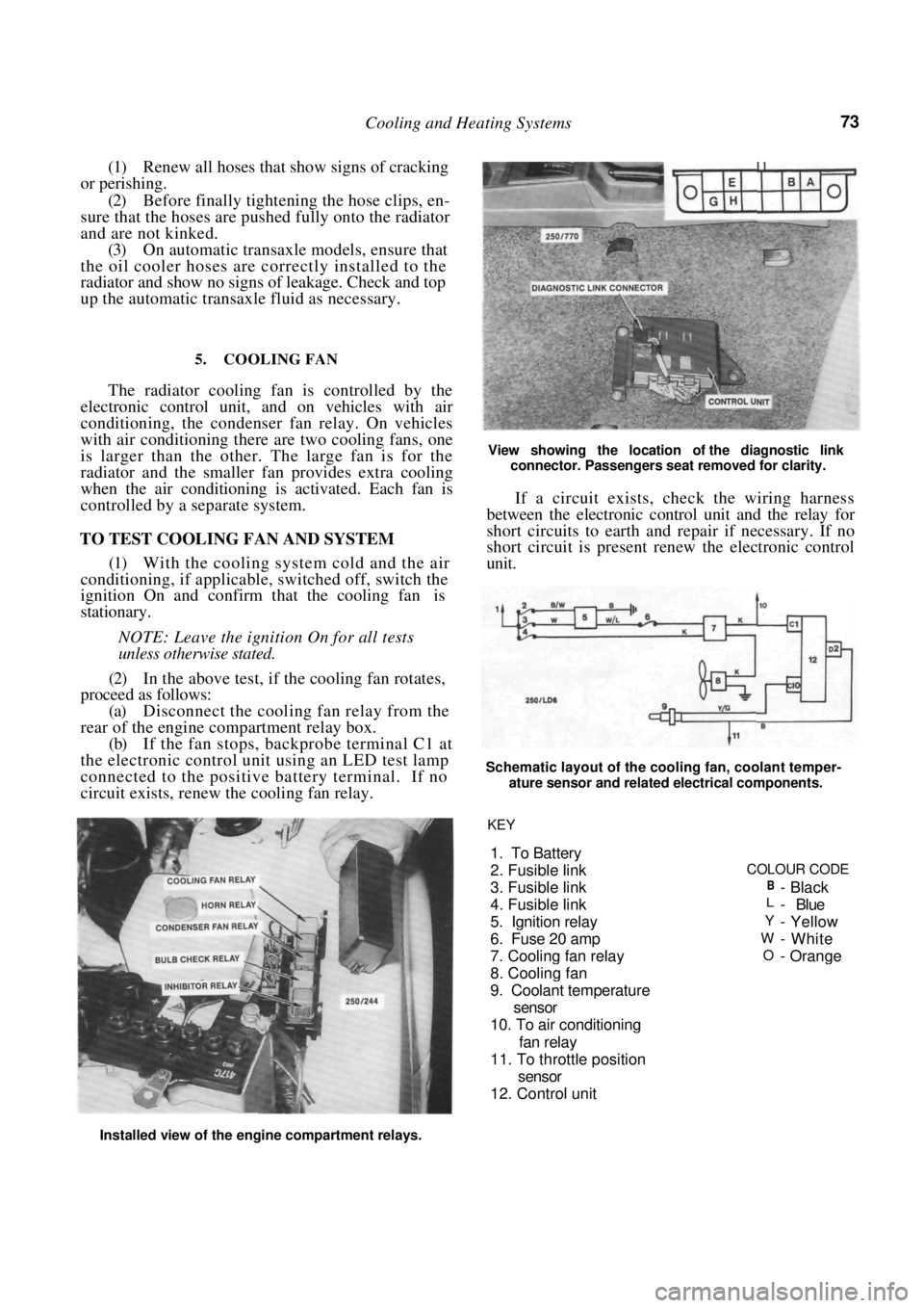
(a) Disconnect the cooling fan relay from the
rear of the engine compartment relay box.
(b) If the fan stops, backprobe terminal C1 at
the electronic control unit using an LED test lamp
connected to the positive battery terminal. If no
circuit exists, renew the cooling fan relay.
View showing the location of the diagnostic link
connector. Passengers seat removed for clarity.
If a circuit exists, check the wiring harness
between the electronic control unit and the relay for
short circuits to earth and repair if necessary. If no
short circuit is present renew the electronic control
unit.
Schematic layout of the cooling fan, coolant temper-
ature sensor and related electrical components.
Installed view of the engine compartment relays. KEY
1. To Battery
2. Fusible link
COLOUR CODE
3. Fusible link
B-Black
4. Fusible linkL- Blue
5. I
gnition relayY- Yellow
6. Fuse 20 am
pW-White
7. Coolin
g fan relayO-Orange
8. Coolin
g fan
9. Coolant tem
perature
sensor
10. To air conditionin
g
fan rela
y
11. To throttle
position
sensor
12. Control unit
Page 74 of 238
74 Cooling and Heating Systems
NOTE: Refer to the Fuel and Engine Man-
agement section for the correct procedure for
backprobing the control unit.
(3) In operation (1) if the cooling fan is station-
ary proceed as follows:
(a) Connect a jumper lead between the terminals
A and B of the diagnostic link connector. (b) if the fan runs, the fan circuit is satisfactory.
If the engine is overheating check the coolant temper-
ature sensor as described in the Fuel and Engine
Management section under the appropriate codes. (c) If the fan does not run, check the fuse (6) and
the fusible link (4) show n on the illustration.
(d) Backprobe terminal C1 at the electronic
control unit using an LED t est lamp connected to the
positive battery terminal. If no circuit exists, renew
the electronic control unit. (e) If the fuse and fusible links are serviceable,
ensure that power is available at the white and pink
wires from the fuse and fusible link of the cooling fan
relay. Repair any faults in the wiring to that point if
necessary. (f) Switch the ignition Off. disconnect the
cooling fan wiring connector at the radiator and
connect power to the fan. Renew the fan if it does not
run.
(4) On air conditioned models, remove the
jumper lead from the ALDL connector if still in-
stalled, start the engine and allow it to idle. Switch the
air conditioning on and ensu re that the cooling fan
runs.
If the cooling fan is opera ting as described above
but cooling system problems still exist, refer to the
Trouble Shooting heading at the start of this section.
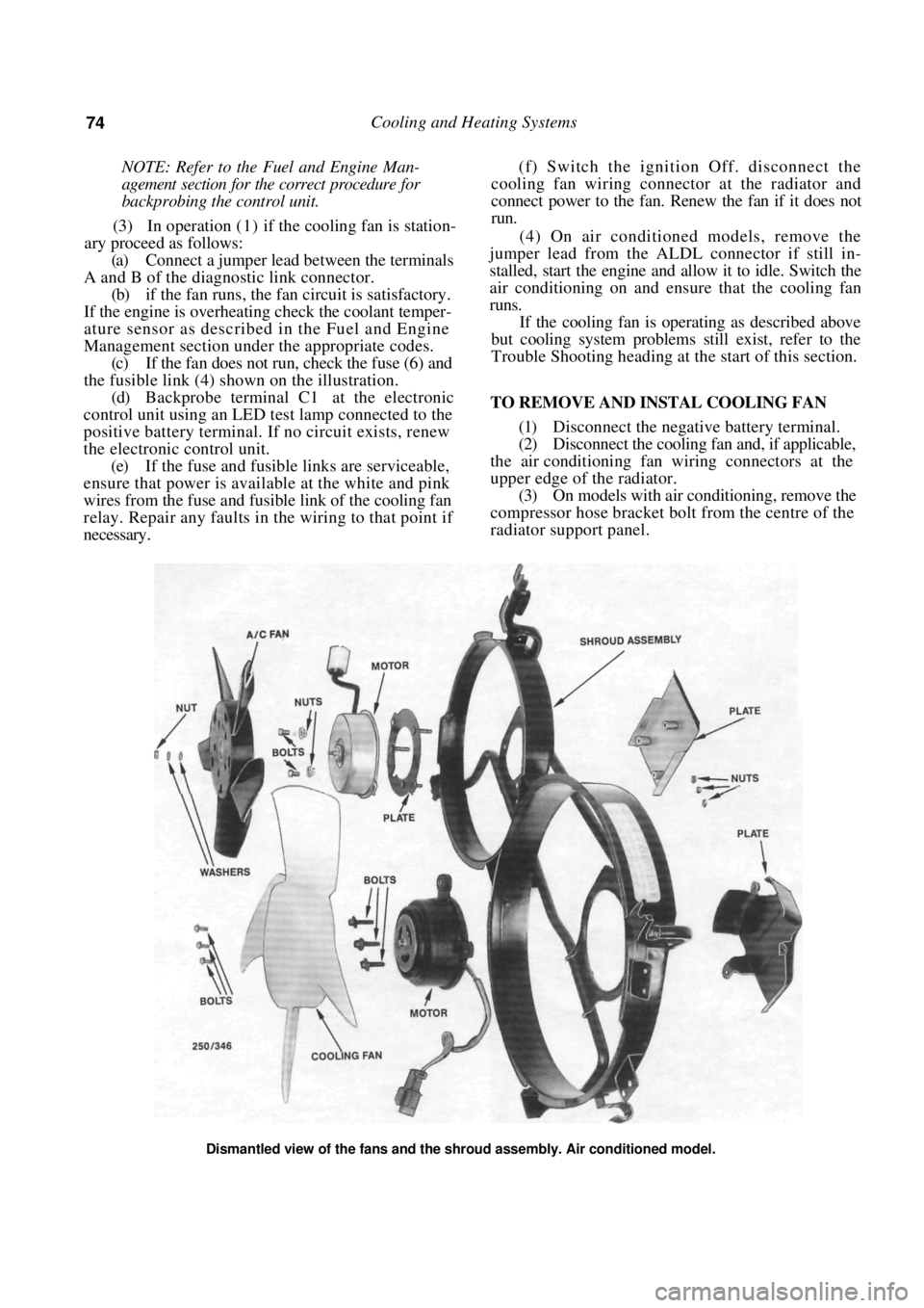
TO REMOVE AND INSTAL COOLING FAN
(1) Disconnect the negative battery terminal.
(2) Disconnect the cooling fa n and, if applicable,
the air conditioning fan wiring connectors at the
upper edge of the radiator. (3) On models with air conditioning, remove the
compressor hose bracket bolt from the centre of the
radiator support panel.
Dismantled view of the fans and the shroud assembly. Air conditioned model.