sensor NISSAN PULSAR 1987 Owner's Guide
[x] Cancel search | Manufacturer: NISSAN, Model Year: 1987, Model line: PULSAR, Model: NISSAN PULSAR 1987Pages: 238, PDF Size: 28.91 MB
Page 120 of 238

120 Emission Control
If the flap does not operate as described, renew
the air cleaner housing.
(2) Disconnect the vacuum hose from the servo
unit and connect it to a vacuum gauge.
(3) Start and run the engine at approximately
1 200 rpm. If the engine is cold there should be
vacuum. (4) As the engine temperature increases the
vacuum should decrease to zero. If the vacuum gauge does not read as described,
check that the vacuum supply hose is connected to the
thermal vacuum valve and the throttle body.
If no fault is found, renew the thermal vacuum
valve.
4. EXHAUST CONTROL SYSTEM
DESCRIPTION
The exhaust system is the greatest source of
pollutant emission from the internal combustion
engine.
On the Pulsar range of vehicles covered by this
manual, the exhaust control system consists of a
catalytic converter and the engine management sys-
tem. The engine management system constantly mon-
itors the exhaust gases via an oxygen sensor located in
the exhaust system. Fuel injection is then adjusted
accordingly to give the minimum amount of exhaust
emissions. Refer to the Fuel and Engine Management
section for further information.
CATALYTIC CONVERTER
The catalytic converter, which is located in the
exhaust system, converts hydrocarbons, oxides of
nitrogen and carbon monoxide present in the exhaust
gases into carbon dioxide, nitrogen, water and heat.
The catalytic converter does not require periodic
maintenance or replacement under normal circum-
stances. However, it can be damaged or poisoned by
excessively high exhaust gas temperatures, raw fuel
and the use of leaded fuel.
Installed view of the catalytic converter.
To prevent the use of leaded fuel, a small diam-
eter fuel filler neck with a spring loaded trap door is
used.
To prevent damage to the catalytic converter, the
following precautions sh ould be observed.
(1) Do not operate the vehicle on leaded fuel.
(2) Do not push or tow start the vehicle.
(3) Do not allow the engine to idle for prolonged
periods. (4) Do not operate the vehicle if the engine is
misfiring.
(5) Avoid running the vehicle out of fuel.
(6) Ensure that the engine oil is formulated to
contain low phosphorous levels.
To Inspect Catalytic Converter
(1) Inspect the converter for dents and damage.
If the converter is damaged, it should be renewed. (2) Inspect the converter heat shield for damage
and ensure that it is positioned correctly. Renew the
converter heat shield if necessary.
To Remove and Install
To remove and install the catalytic converter,
refer
to the Exhaust System heading in the Engine section.
Page 129 of 238

Manual Transaxle and Drive Shafts 129
renewed as individual units. The C.V. joints are
lubricated in manufacture and need no attention in
service unless one of the r ubber boots is damaged. In
this case the joint can be cl eaned and repacked with
the recommended grease and a new boot installed.
From July 1989, Pulsar Q and Vector SSS manual
transaxle models are equipped with a limited slip
differential incorporating a viscous coupling. The
coupling is not repairable and must be renewed as an
assembly if unserviceable. A test procedure for the
viscous coupling is included in the text in this section.
3. TRANSAXLE ASSEMBLY
Special Equipment Required:
To Dismantle and Assemble — Puller set, press
and press plates, dial gauge
To Measure Mainshaft Turning Torque —
Suitable slotted adaptor and torque gauge
TO REMOVE AND INSTAL
(1) Raise the front of the vehicle and support it
on chassis stands.
(2) Remove the battery as described in the
Electrical System section. (3) Remove the drive shafts as described later in
this section. (4) Disconnect and remove the starter motor as
described in the Elect rical System section.
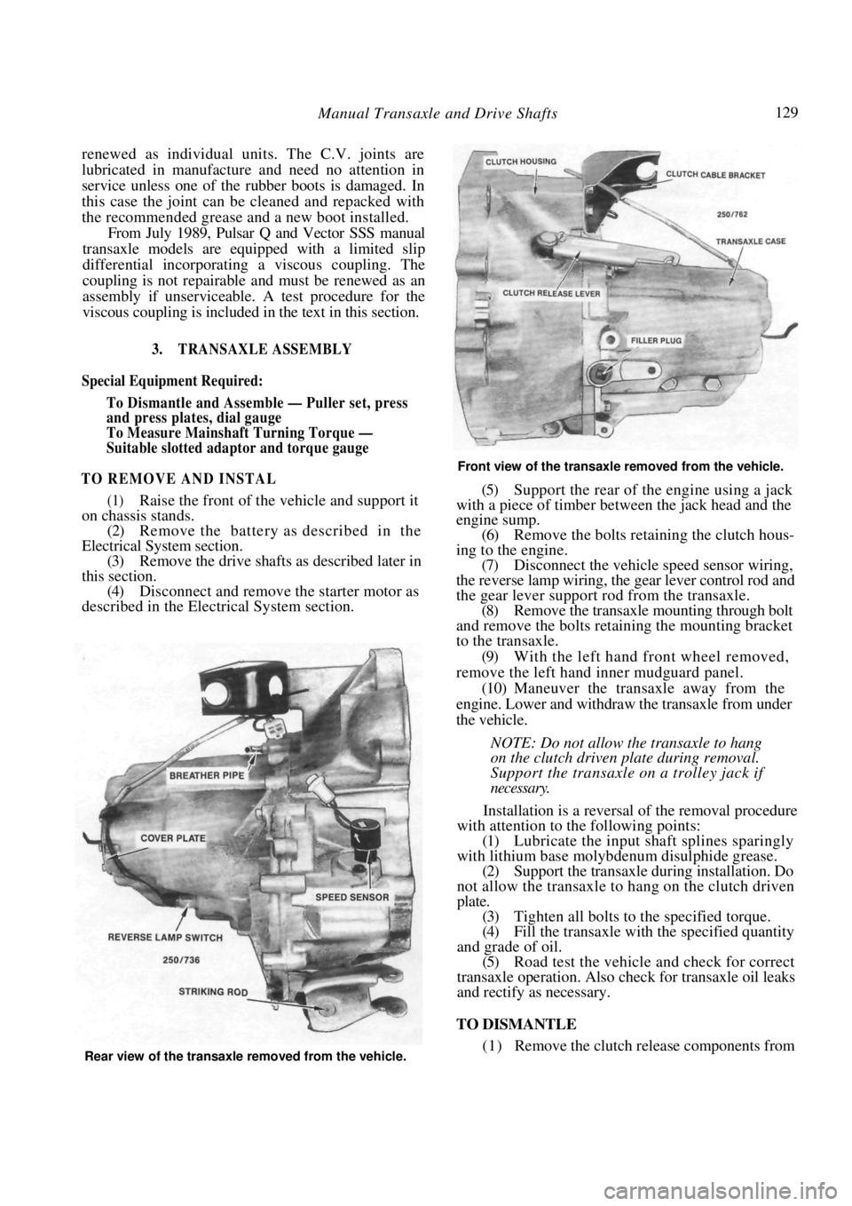
Front view of the transaxle removed from the vehicle.
(5) Support the rear of the engine using a jack
with a piece of timber between the jack head and the
engine sump.
(6) Remove the bolts retaining the clutch hous-
ing to the engine. (7) Disconnect the vehicle speed sensor wiring,
the reverse lamp wiring, the gear lever control rod and
the gear lever support rod from the transaxle. (8) Remove the transaxle mounting through bolt
and remove the bolts retaining the mounting bracket
to the transaxle.
(9) With the left hand front wheel removed,
remove the left hand inner mudguard panel. (10) Maneuver the transaxle away from the
engine. Lower and withdraw the transaxle from under
the vehicle.
NOTE: Do not allow the transaxle to hang
on the clutch driven plate during removal.
Support the transaxle on a trolley jack if
necessary.
Installation is a reversal of the removal procedure
with attention to the following points:
(1) Lubricate the input shaft splines sparingly
with lithium base molybdenum disulphide grease. (2) Support the transaxle during installation. Do
not allow the transaxle to hang on the clutch driven
plate. (3) Tighten all bolts to the specified torque.
(4) Fill the transaxle with the specified quantity
and grade of oil. (5) Road test the vehicle and check for correct
transaxle operation. Also ch eck for transaxle oil leaks
and rectify as necessary.
TO DISMANTLE
(1) Remove the clutch release components from Rear view of the transaxle removed from the vehicle.
Page 143 of 238

Automatic Transaxle 143
facing towards the radiator support panel at the front
of the vehicle.
The neutral safety switch allows electrical current
to pass to the starter circ uit only when the selector
lever is in the Park or Neutral position. The switch is
adjustable but non-repairable.
TO TEST
(1) Disconnect the neutral safety switch wiring
connector.
(2) Connect an ohmmeter between terminals 1
and 2 at the neutral safety switch wiring connector.
Continuity should exist when the selector lever is in
the P or N positions. (3) Perform the same check with terminals 3 and
4 with the selector lever in the R position. Continuity
should exist.
NOTE: If the readings are other than that
specified, the neutral safety switch will have
to be adjusted or renewed.
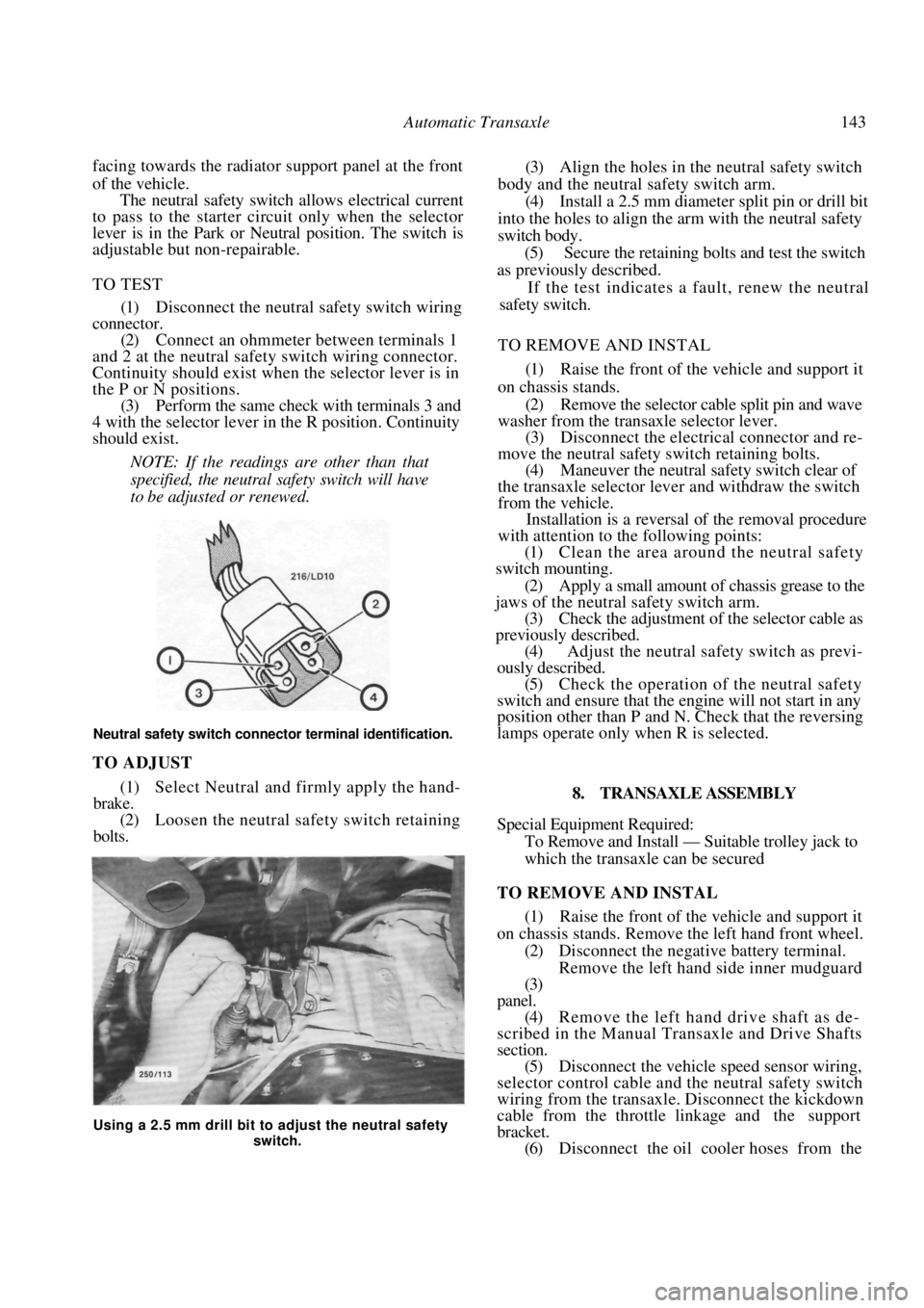
Neutral safety switch connector terminal identification.
TO ADJUST
(1) Select Neutral and firmly apply the hand-
brake. (2) Loosen the neutral safety switch retaining
bolts.
(3) Align the holes in the neutral safety switch
body and the neutral safety switch arm. (4) Install a 2.5 mm diameter split pin or drill bit
into the holes to align the arm with the neutral safety
switch body. (5) Secure the retaining bolts and test the switch
as previously described.
If the test indicates a fault, renew the neutral
safety switch.
TO REMOVE AND INSTAL
(1) Raise the front of the vehicle and support it
on chassis stands. (2) Remove the selector cable split pin and wave
washer from the transaxle selector lever.
(3) Disconnect the electric al connector and re-
move the neutral safety switch retaining bolts. (4) Maneuver the neutral safety switch clear of
the transaxle selector lever and withdraw the switch
from the vehicle. Installation is a reversal of the removal procedure
with attention to the following points:
(1) Clean the area around the neutral safety
switch mounting.
(2) Apply a small amount of chassis grease to the
jaws of the neutral safety switch arm. (3) Check the adjustment of the selector cable as
previously described. (4) Adjust the neutral safety switch as previ-
ously described.
(5) Check the operation of the neutral safety
switch and ensure that the engine will not start in any
position other than P and N. Check that the reversing
lamps operate only when R is selected.
8. TRANSAXLE ASSEMBLY
Special Equipment Required:
To Remove and Install — Suitable trolley jack to
which the transaxle can be secured
TO REMOVE AND INSTAL
(1) Raise the front of the vehicle and support it
on chassis stands. Remove the left hand front wheel.
(2) Disconnect the negative battery terminal. Remove the left hand side inner mudguard
(3)
panel.
(4) Remove the left hand drive shaft as de-
scribed in the Manual Tran saxle and Drive Shafts
section. (5) Disconnect the vehicle speed sensor wiring,
selector control cable and the neutral safety switch
wiring from the transaxle. Disconnect the kickdown
cable from the throttle linkage and the support
bracket. (6) Disconnect the oil cooler hoses from the
Using a 2.5 mm drill bit to adjust the neutral safety
switch.
Page 220 of 238

220 Electrical System
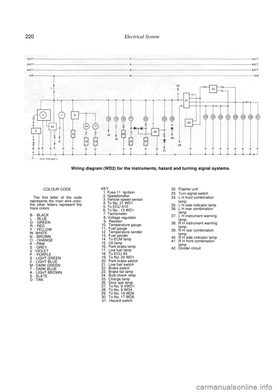
Wiring diagram (WD2) for the instruments, hazard and turning signal systems.
COLOUR CODE
The first letter of the code
represents the main wire color,
the other letters represent the
trace colors.
B - BLACK
L - BLUE
G - GREEN
R - RED
Y - YELLOW
W- WHITE
N - BROWN
O - OHANGE
K - PINK
S - GREY V -VIOLET
P - PURPLE X - LIGHT GREEN Z - LIGHT BLUE M - DARK GREEN T - DARK BLUE A - LIGHT BROWN E - SLATE D - TAN
KEY 1. Fuse 11 Ignition
2. Speedometer
3. Vehicle speed sensor
4. To No. 21 WD1
5. To ECU A10
6. To No. 13 WD1
7. Tachometer
8. Voltage regulator
9. Resistor
10. Temperature gauge
11. Fuel gauge
12. Temperature sender
13. Fuel sender
14. To ECM lamp
15. Oil lamp
16. Park brake lamp
17. Low fuel lamp
18. To ECU A5
19. To No. 20 WD1
20. Park brake switch
21. Low fuel switch
22. Brake switch
23. Brake fail lamp
24. Bulb check relay
25. Charge lamp
26. Door ajar lamp
27. To No. 6 VWD1
28. To No. 8 WD4
29. To No. 18 WD6
30. To No. 17 WD6 31. Hazard switch
32. Flasher unit
33. Turn signal switch
34. L H front combination
lamp
35. L H side indicator lamp
36. L H rear combination lamp
37. L H instrument warning
lamp
38. R H instrument warning lamp
39. R H rear combination lamp
40. R H side indicator lamp
41. R H front combination lamp
42. Divider circuit