torque NISSAN PULSAR 1987 Workshop Manual
[x] Cancel search | Manufacturer: NISSAN, Model Year: 1987, Model line: PULSAR, Model: NISSAN PULSAR 1987Pages: 238, PDF Size: 28.91 MB
Page 8 of 238
GENERAL INFORMATION
1. TOOLS AND EQUIPMENT
To successfully perform any maintenance or re-
pair work on a motor vehicle, suitable hand tools are
essential. The use of tools for other than their intend-
ed purpose or the use of incorrectly fitting tools can
cause damage to the componen t and/or injury lo the
operator.
BASIC TOOL KIT
The following is a sugg ested list of tools and
equipment for the majority of the maintenance and
repair procedures described in this manual. Of course,
not all of the tools are required for all the jobs, so it is
wise to purchase tools on an 'as needed' basis.
Set of open ended spanners.
Set of ring spanners.
Set of socket spanners.
Spark plug spanner.
Assorted bladed screwdrivers.
Assorted Philips screwdrivers.
Assorted pliers — combination, long nose, multi-
grip, vice grip, snap ring (internal and external).
Assorted adjustable spanners.
Ball pein hammer.
Cold chisels.
Pin punches and centre punch.
Assorted files.
Scraper.
Feeler gauges.
Torque wrench.
Hydraulic jack.
Chassis stands.
Car ramps.
Grease gun.
Oil can.
Oil gun.
Oil filter removal tool.
Funnel.
Containers for draining oil and washing compon-
ents.
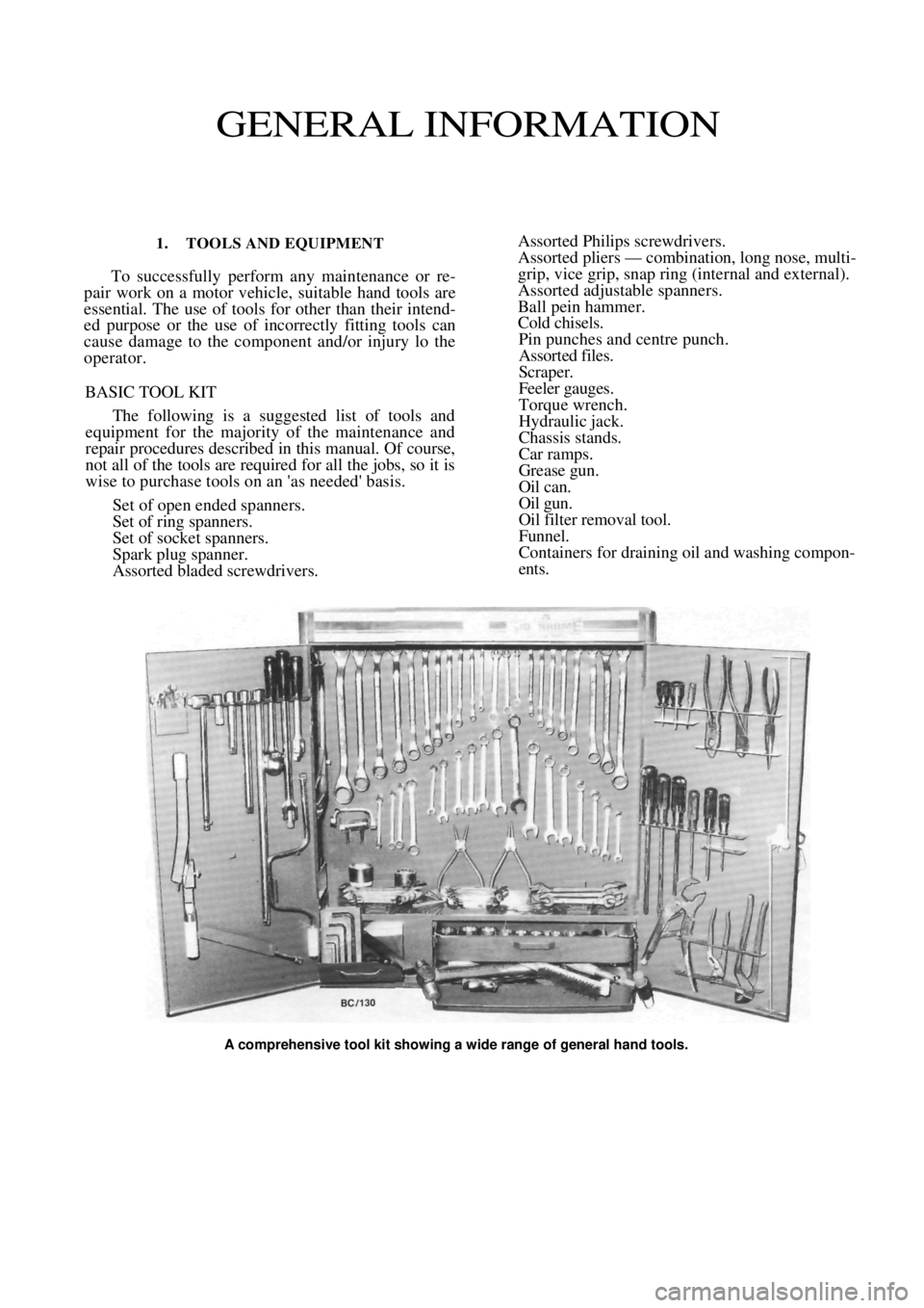
A comprehensive tool kit showing a wide range of general hand tools.
Page 21 of 238
WHEELS AND TYRES
SPECIFICATIONS
TYRES PRESSURES
Front:
Normal load ............................................ 200 kPa
Heavy load or high speed ......................230 kPa
Rear:
Normal load............................................ 180 kPa
Heavy load or high speed ...................... 210 kPa
NOTE: The above pressures are measured
cold and are meant as a guide only. Always
refer to the tire placard positioned on the
inside of the glove compartment lid and the
tire manufacturers recommendations first.
TORQUE WRENCH SETTINGS
Wheel nut torque .............................................98 Nm
1. HOW TO CHANGE A ROAD WHEEL
(1) Ensure that the vehicle is on level firm
ground and clear of any passing traffic. (2) If necessary, switch on the hazard
flashers.
(3) Switch off the engine a nd place the transaxle
in the (P) Park position on automatic transaxle
models or in reverse gear on manual transaxle models.
(4) Apply the handbrake firmly and chock the
front and rear of the wheel diagonally opposite the
wheel being changed.
(5) Remove the spare wheel, tool kit and jack
located in the luggage compartment. (6) On vehicles equipped with full wheel covers,
remove the trim from the wheel. (7) Using the wheel spanner, loosen the wheel
nuts progressively in a diagonal sequence half a turn.
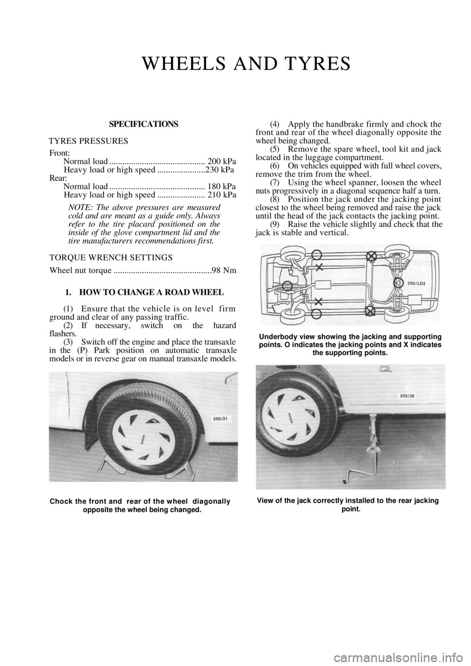
(8) Position the jack und er the jacking point
closest to the wheel being removed and raise the jack
until the head of the jack contacts the jacking point.
(9) Raise the vehicle slightly and check that the
jack is stable and vertical.
Underbody view showing the jacking and supporting
points. O indicates the jacking points and X indicates
the supporting points.
Chock the front and rear of the wheel diagonally
opposite the wheel being changed. View of the jack correctly installed to the rear jacking
point.
Page 25 of 238
25
ENGINE TUNE-UP
CAUTION: To prevent severe electrical shock, extreme care must be taken when
working on or near the electronic ignition system as dangerous high tension voltages
are produced in both the primary and secondary circuits. See the text fo\
r
precautionary notes.
1. TUNE-UP SPECIFICATIONS
Firing orde r................................................... 1 -3-4-2
Spark plugs:
Type .............................................NGK BPR 6ES
Gap ........................................................... 1.1 mm
Tightening torque...................................... 20 Nm
Ignition timing with diagnostic link
connector jumped........................... 10 deg BTDC
Idle speed (ECU controlled):
Manual transaxle 1.8 liter ............ 850 ± 50 rpm
Manual transaxle 1.6 liter............800 ± 50 rpm
Automatic transaxle
(Park or Neutral).......................... 825 ± 50 rpm
Drive belt deflection:
Alternator ........................................... 14-16 mm
Power steering pump ......................... 14-16 mm
Air conditioner compressor .................. 9-11 mm
NOTE: When performing an engine tune-
up, a/ways compare the above Specifications
with the emission control information label
inside the engine compartment.
2. TUNE-UP OPERATIONS
Special Equipment Required:
To Test Compression — Compression gauge
TO SERVICE AIR CLEANER
The air cleaner is equipped with a paper element.
The element should be regu larly inspected but should
not be cleaned in service.
The element should be renewed every 40 000 km.
This distance is only a guide for normal operating
conditions and should be reduced accordingly if the
vehicle is operating under ex tremely dusty conditions.
NOTE: Paper air cleaner elements should
not be washed in petrol or any other type of
cleaning solvent. If the element has been
washed in solvent or has become oil soaked,
it should be discarded and a new element
installed.
1.8 Liter Engine
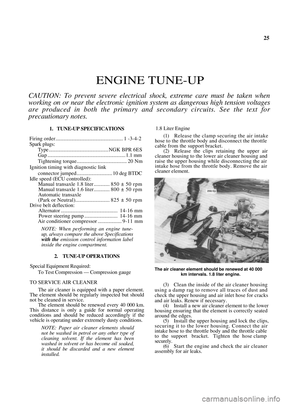
(1) Release the clamp securing the air intake
hose to the throttle body and disconnect the throttle
cable from the support bracket. (2) Release the clips reta ining the upper air
cleaner housing to the lowe r air cleaner housing and
raise the upper housing while disconnecting the air
intake hose from the throttle body. Remove the air
cleaner element.
The air cleaner element should be renewed at 40 000
km intervals. 1.8 liter engine.
(3) Clean the inside of the air cleaner housing
using a damp rag to remove all traces of dust and
check the upper housing and air inlet hose for cracks
and air leaks. Renew if necessary. (4) Install a new air cleaner element to the lower
housing ensuring that the element is correctly seated
around the edges. (5) Install the upper housing and lock the clips,
securing it to the lower housing. Connect the air
intake hose to the throttle body and the throttle cable
to the support bracket. Tighten the hose clamp
securely. (6) Start the engine and check the air cleaner
assembly for air leaks.
Page 28 of 238
Engine Tune-up
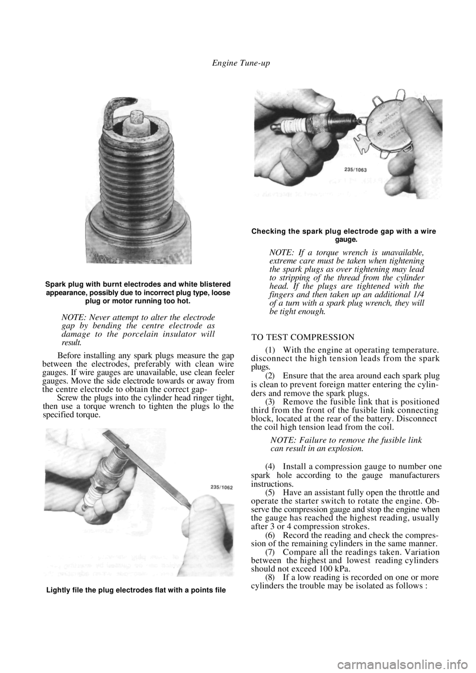
Spark plug with burnt electrodes and white blistered
appearance, possibly due to incorrect plug type, loose
plug or motor running too hot.
NOTE: Never attempt to alter the electrode
gap by bending the centre electrode as
damage to the porcelain insulator will
result.
Before installing any spark plugs measure the gap
between the electrodes, pref erably with clean wire
gauges. If wire gauges are una vailable, use clean feeler
gauges. Move the side electrode towards or away from
the centre electrode to obtain the correct gap-
Screw the plugs into the cylinder head ringer tight,
then use a torque wrench to tighten the plugs lo the
specified torque.
Checking the spark plug electrode gap with a wire
gauge.
NOTE: If a torque wrench is unavailable,
extreme care must be taken when tightening
the spark plugs as over tightening may lead
to stripping of the thread from the cylinder
head. If the plugs are tightened with the
fingers and then taken up an additional 1/4
of a turn with a spark plug wrench, they will
be tight enough.
TO TEST COMPRESSION
(1) With the engine at operating temperature.
disconnect the high tension leads from the spark
plugs.
(2) Ensure that the area around each spark plug
is clean to prevent foreign matter entering the cylin-
ders and remove the spark plugs. (3) Remove the fusible link that is positioned
third from the front of th e fusible link connecting
block, located at the rear of the battery. Disconnect
the coil high tension lead from the coil.
NOTE: Failure to remove the fusible link
can result in an explosion.
(4) Install a compression gauge to number one
spark hole according to the gauge manufacturers
instructions. (5) Have an assistant fully open the throttle and
operate the starter switch to rotate the engine. Ob-
serve the compression gauge and stop the engine when
the gauge has reached the highest reading, usually
after 3 or 4 compression strokes.
(6) Record the reading a nd check the compres-
sion of the remaining cylinders in the same manner.
(7) Compare all the readings taken. Variation
between the highest and lowest reading cylinders
should not exceed 100 kPa. (8) If a low reading is recorded on one or more
cylinders the trouble may be isolated as follows :
Lightly file the plug electrodes flat with a points file
Page 38 of 238

38 Engine
*Piston skirt to cylinder bore clearance:
1.6 liter .....................................0. 020-0.040 mm
1.8 liter .....................................0. 010-0.030 mm
Gudgeon pin length:
1.6 liter ...................................................... 53 mm
1.8 liter .................................................. 61.5 mm
Gudgeon pin diameter.................20.990-20.995 mm
Gudgeon pin clearance in piston:
1.6 liter .....................................0. 010-0.020 mm
1.8 liter ..................................0. 0055-0.0115 mm
Gudgeon pin offset in piston:
1.6 liter......... 0.35-0.65 mm towards thrust side
1.8 liter................... 0.8 mm towards thrust side
*Measured 9 mm from the bottom of the piston skirt
for 1.6 liter models and 6 mm from the bottom of the
piston skirt for 1.8 liter models.
PISTON RINGS
Rings per piston:
Compression .......................................................2
Oil contro l .......................................................... 1
End gap:
Compression ................................ 0.30-0.50 mm
Oil control —
1.6 liter ......................................... 0.33-1.10 mm
1.8 liter ......................................... 0.40-1.40 mm
CONNECTING RODS AND BEARINGS
Connecting rod side clearance............ 0.07-0.24 mm
Maximum connecting rod weight variation..8 grams
Crankpin bearing oil clearance ....... 0. 019-0.063 mm
CRANKSHAFT AND MAIN BEARINGS
Number of bearings .................................................. 5
End float taken at ...................... No. 3 main bearing
End float .......................................... 0.070-0.302 mm
Bend limit ...................................................0.03 mm
Main bearing oil clearance .............0. 015-0.040 mm
Main bearing journal diameter.. .57.982-57.995 mm
Crankpin diameter .......................48.971-48.987 mm
FLYWHEEL
Ring gear run out limit.................................. 0.3 mm
Clutch face regrind limit .............................. 0.3 mm
CAMSHAFT
Drive ...................................................... Toothed belt
End float .............................................. 0.04-0.14 mm
Bend limit ................................................... 0.03 mm
Bearings ...........................................Direct in housing
Journal diameter:
Standard —
No. 1 ..................................... 42. 455-42.470 mm
No. 2 ..................................... 42. 705-42.720 mm
No. 3 ..................................... 42.955-42.970 mm
No. 4 ..................................... 43.205-43.220 mm
No. 5 ..................................... 43.455-43.470 mm
Undersize —
No. 1 .....................................42.355-42.370 mm
No. 2 ......................................42.605-42.620 mm
No. 3 .....................................42.855-42.880 mm
No. 4 ......................................43.105-43.120 mm
No. 5 .....................................43. 355-43.370 mm
*An undersize camshaft can be identified by a violet
flash between the inlet and exhaust lobes of No. 2
cylinder.
Housing diameter;
Standard —
No. 1 .....................................42. 500-42.525 mm
No. 2 .....................................42.750-42.775 mm
No. 3 .....................................43.000-43.025 mm
No. 4 ......................................43.250-43.275 mm
No. 5 .....................................43.500-43.525 mm
*Undersize —
No. 1 .....................................42.400-42.425 mm
No. 2 .....................................42.650-42.675 mm
No. 3 .....................................42.900-42.925 mm
No. 4 ......................................43.150-43.175 mm
No. 5 .....................................43.400-43.425 mm
*An undersize camshaft housing can be identified by
a violet flash on the centre camshaft bearing support.
LUBRICATION
Oil pump type .......................................Involute gear
Filter type................................... Full flow disposable
Oil pressure at 4 000 rpm .....................480-620 kPa
Rotor assembly end float .................. 0.03-0. 010 mm
Rotor teeth backlash ......................... 0.010-0.20 mm
TORQUE WRENCH SETTINGS
*Cylinder head bolts:
Initial torque ............................................. 25 Nm
1st stage ......................................... + 60 degrees
2nd stage ........................................ + 60 degrees
3rd stage......................................... + 60 degrees
4th stage, engine at operating
temperature .............................. + 30-50 degrees
Exhaust manifold nuts .................................... 22 Nm
Exhaust manifold flange nuts ......................... 22 Nm
Inlet manifold nuts.......................................... 22 Nm
Throttle body to inlet manifold nuts ..............12 Nm
Camshaft liming gear bolt ...............................45 Nm
Camshaft retainin g plate bolts ......................... 7 Nm
Camshaft cover bolts......................................... 8 Nm
Thermostat cover bolts ....................................15 Nm
*Main bearing bolts..................60 Nm + 45 degrees
Connecting rod bearing
cap nuts ................................... 35 Nm + 45 degrees
* Crankshaft timing
gear bolt.................................. 145 Nm + 35 degrees
*Flywheel bolts
(microencapsulated) ................ 60 Nm + 30 degrees
*Drive plate bolts (microencapsulated)........... 60 Nm
Water pump bolts............................................ 25 Nm
Page 39 of 238
Engine 39
Oil pump cover plate screws............................ 6 Nm
Oil pump mounting bolts.................................. 6 Nm
Oil pump pickup bolts
(coat with Loctite 242)..................................... 8 Nm
Sump bolts (coat with Loctite 242) .................. 5 Nm
Sump drain plug .............................................. 35 Nm
*Use new bolts
Head bolts maximum torque 135 Nm
1. ENGINE MECHANICAL TROUBLE
SHOOTING
ENGINE MISSES AT IDLING SPEED
NOTE: For other causes of engine misfire,
refer to the Fuel and Engine Management
section.
(1) Blown head gasket: Check the cylinder com-
pressions and renew the he ad gasket as necessary.
(2) Burnt valves or seats in the cylinder head:
Check the cylinder compressions and overhaul the
cylinder head as necessary. (3) Broken or worn piston rings: Check the
cylinder compressions and renew the piston rings as
necessary.
(4) Weak or broken valve springs: Remove the
camshaft housing top cover and check the condition
of the valve springs. (5) Air leak at the inlet manifold gasket; Check
for air leaks by applying oil around the manifold
joints. Renew the gasket if an air leak is evident.
NOTE: Use a compre ssion gauge and check
the compression pressure in each cylinder as
described in the Engine Tune-up section. If
a low pressure reading is indicated in one or
more cylinders, remove the cylinder head for
gasket and valve inspection. Should the
gasket and valves prove satisfactory, inspect
the cylinder bores, pistons and rings.
Check for air leaks at the inlet manifold
by applying engine oil around the manifold
joints. If the oil can be seen or heard sucking
into the manifold or excessive smoke begins
to issue from the exhaust system, there is an
air leak at the inlet manifold.
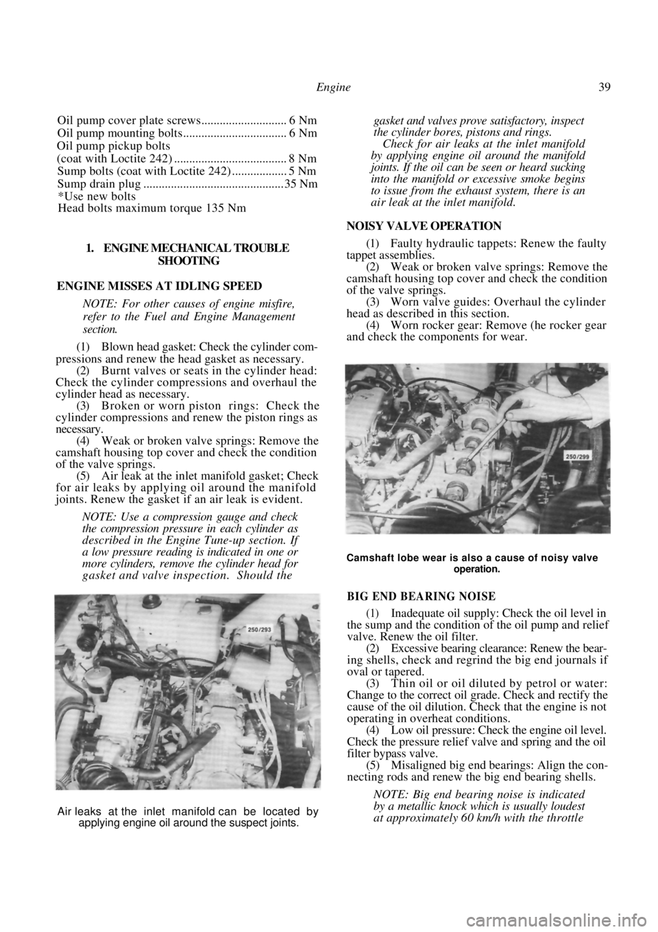
NOISY VALVE OPERATION
(1) Faulty hydraulic tappets: Renew the faulty
tappet assemblies. (2) Weak or broken valve springs: Remove the
camshaft housing top cover and check the condition
of the valve springs. (3) Worn valve guides: Overhaul the cylinder
head as described in this section. (4) Worn rocker gear: Remove (he rocker gear
and check the components for wear.
Camshaft lobe wear is also a cause of noisy valve
operation.
BIG END BEARING NOISE
(1) Inadequate oil supply: Check the oil level in
the sump and the condition of the oil pump and relief
valve. Renew the oil filter.
(2) Excessive bearing clearance: Renew the bear-
ing shells, check and regrind the big end journals if
oval or tapered. (3) Thin oil or oil diluted by petrol or water:
Change to the correct oil grade. Check and rectify the
cause of the oil dilution. Ch eck that the engine is not
operating in overheat conditions.
(4) Low oil pressure: Check the engine oil level.
Check the pressure relief valve and spring and the oil
filter bypass valve. (5) Misaligned big end bearings: Align the con-
necting rods and renew the big end bearing shells.
NOTE: Big end bearing noise is indicated
by a metallic knock wh ich is usually loudest
at approximately 60 km/h with the throttle
Air leaks at the inlet manifold can be located by
applying engine oil around the suspect joints.
Page 40 of 238
40 Engine
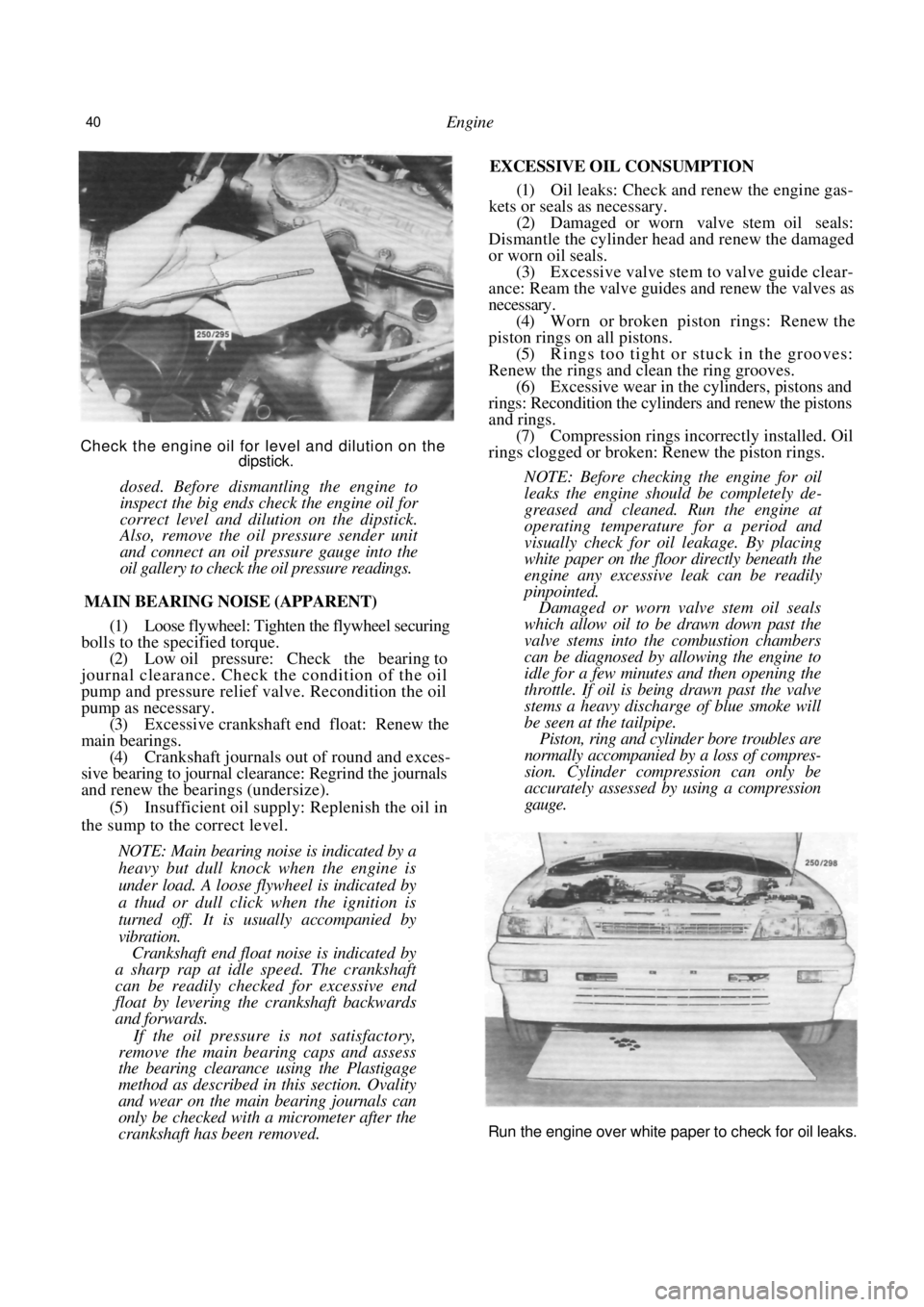
Check the engine oil for level and dilution on the dipstick.
dosed. Before dismantling the engine to
inspect the big ends check the engine oil for
correct level and dilution on the dipstick.
Also, remove the oil pressure sender unit
and connect an oil pressure gauge into the
oil gallery to check the oil pressure readings.
MAIN BEARING NOISE (APPARENT)
(1) Loose flywheel: Tighten the flywheel securing
bolls to the specified torque. (2) Low oil pressure: Check the bearing to
journal clearance. Check the condition of the oil
pump and pressure relief valve. Recondition the oil
pump as necessary. (3) Excessive crankshaft end float: Renew the
main bearings. (4) Crankshaft journals out of round and exces-
sive bearing to journal clear ance: Regrind the journals
and renew the bearings (undersize).
(5) Insufficient oil supply: Replenish the oil in
the sump to the correct level.
NOTE: Main bearing noise is indicated by a
heavy but dull knock when the engine is
under load. A loose flywheel is indicated by
a thud or dull click when the ignition is
turned off. It is us ually accompanied by
vibration.
Crankshaft end float noise is indicated by
a sharp rap at idle speed. The crankshaft
can be readily checked for excessive end
float by levering the crankshaft backwards
and forwards.
If the oil pressure is not satisfactory,
remove the main bearing caps and assess
the bearing clearance using the Plastigage
method as described in this section. Ovality
and wear on the main bearing journals can
only be checked with a micrometer after the
crankshaft has been removed.
EXCESSIVE OIL CONSUMPTION
(1) Oil leaks: Check and renew the engine gas-
kets or seals as necessary.
(2) Damaged or worn valve stem oil seals:
Dismantle the cylinder head and renew the damaged
or worn oil seals. (3) Excessive valve stem to valve guide clear-
ance: Ream the valve guides and renew the valves as
necessary. (4) Worn or broken piston rings: Renew the
piston rings on all pistons. (5) Rings too tight or stuck in the grooves:
Renew the rings and clean the ring grooves.
(6) Excessive wear in the cylinders, pistons and
rings: Recondition the cylinders and renew the pistons
and rings. (7) Compression rings incorrectly installed. Oil
rings clogged or broken: Renew the piston rings.
NOTE: Before checking the engine for oil
leaks the engine should be completely de-
greased and cleaned. Run the engine at
operating temperature for a period and
visually check for oil leakage. By placing
white paper on the floor directly beneath the
engine any excessive leak can be readily
pinpointed.
Damaged or worn valve stem oil seals
which allow oil to be drawn down past the
valve stems into the combustion chambers
can be diagnosed by allowing the engine to
idle for a few minutes and then opening the
throttle. If oil is being drawn past the valve
stems a heavy discharge of blue smoke will
be seen at the tailpipe.
Piston, ring and cylinder bore troubles are
normally accompanied by a loss of compres-
sion. Cylinder compression can only be
accurately assessed by using a compression
gauge.
Run the engine over white paper to check for oil leaks.
Page 45 of 238
Engine 45
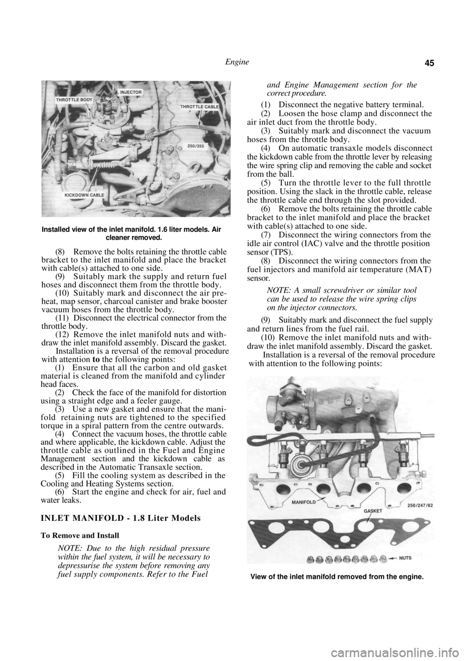
Installed view of the inlet manifold. 1.6 liter models. Air
cleaner removed.
(8) Remove the bolts retaining the throttle cable
bracket to the inlet manifold and place the bracket
with cable(s) attached to one side.
(9) Suitably mark the supply and return fuel
hoses and disconnect them from the throttle body.
(10) Suitably mark and disconnect the air pre-
heat, map sensor, charcoal canister and brake booster
vacuum hoses from the throttle body. (11) Disconnect the electrical connector from the
throttle body. (12) Remove the inlet manifold nuts and with-
draw the inlet manifold assembly. Discard the gasket. Installation is a reversal of the removal procedure
with attention to the following points:
(1) Ensure that all the carbon and old gasket
material is cleaned from the manifold and cylinder
head faces. (2) Check the face of the manifold for distortion
using a straight edge and a feeler gauge. (3) Use a new gasket and ensure that the mani-
fold retaining nuts are tightened to the specified
torque in a spiral pattern from the centre outwards. (4) Connect the vacuum hoses, the throttle cable
and where applicable, the kickdown cable. Adjust the
throttle cable as outlined in the Fuel and Engine
Management section and the kickdown cable as
described in the Automatic Transaxle section. (5) Fill the cooling system as described in the
Cooling and Heating Systems section. (6) Start the engine and check for air, fuel and
water leaks.
INLET MANIFOLD - 1.8 Liter Models
To Remove and Install
NOTE: Due to the high residual pressure
within the fuel system, it will be necessary to
depressurise the system before removing any
fuel supply components. Refer to the Fuel
and Engine Management section for the
correct procedure.
(1) Disconnect the negative battery terminal.
(2) Loosen the hose clamp and disconnect the
air inlet duct from the throttle body. (3) Suitably mark and disconnect the vacuum
hoses from the throttle body. (4) On automatic transaxle models disconnect
the kickdown cable from the throttle lever by releasing
the wire spring clip and re moving the cable and socket
from the ball. (5) Turn the throttle lever to the full throttle
position. Using the slack in the throttle cable, release
the throttle cable end thr ough the slot provided.
(6) Remove the bolts retaining the throttle cable
bracket to the inlet manifold and place the bracket
with cable(s) attached to one side. (7) Disconnect the wiring connectors from the
idle air control (IAC) valve and the throttle position
sensor (TPS).
(8) Disconnect the wiring connectors from the
fuel injectors and manifold air temperature (MAT)
sensor.
NOTE: A small screwdriver or similar tool
can be used to release the wire spring clips
on the injector connectors.
(9) Suitably mark and disconnect the fuel supply
and return lines from the fuel rail. (10) Remove the inlet manifold nuts and with-
draw the inlet manifold assembly. Discard the gasket. Installation is a reversal of the removal procedure
with attention to the following points:
View of the inlet manifold removed from the engine.
Page 46 of 238
46 Engine
(1) Ensure that all carbon and old gasket mate-
rial is cleaned from the manifold and cylinder head
faces. (2) Check the face of the manifold for distortion
using a straight edge and a feeler gauge. (3) Use a new gasket and ensure that the mani-
fold retaining nuts are tightened to the specified
torque in a spiral pattern from the centre outwards. (4) Adjust the throttle cabl e as described in the
Fuel and Engine Management section and the kick-
down cable as described in the Automatic Transaxle
section.
(5) Start the engine and check for air, fuel and
water leaks.
EXHAUST MANIFOLD
To Remove and Install
(1) Bring the engine to operating temperature
and remove the oxygen sensor.
(2) Disconnect the negative battery terminal.
(3) On 1.6 liter models, remove the air cleaner
nuts, disconnect the vacuum hose and withdraw the
air cleaner from the vehicle. (4) Remove the front exhaust pipe flange mount-
ing nuts and separate the exhaust pipe from the
manifold. (5) Remove the heat shield retaining bolts and
withdraw the heat shield from the exhaust manifold. (6) Remove the exhaust manifold to cylinder
head retaining nuts and remove the manifold from the
engine. Discard the manifold gasket. Installation is a reversal of the removal procedure
with attention to the following points:
(1) Ensure that all carbon is cleaned from the
manifold and cylinder head mating surfaces. (2) Check the face of the manifold for distortion
using a straight edge and feeler gauges. (3) Use new gaskets on assembly.
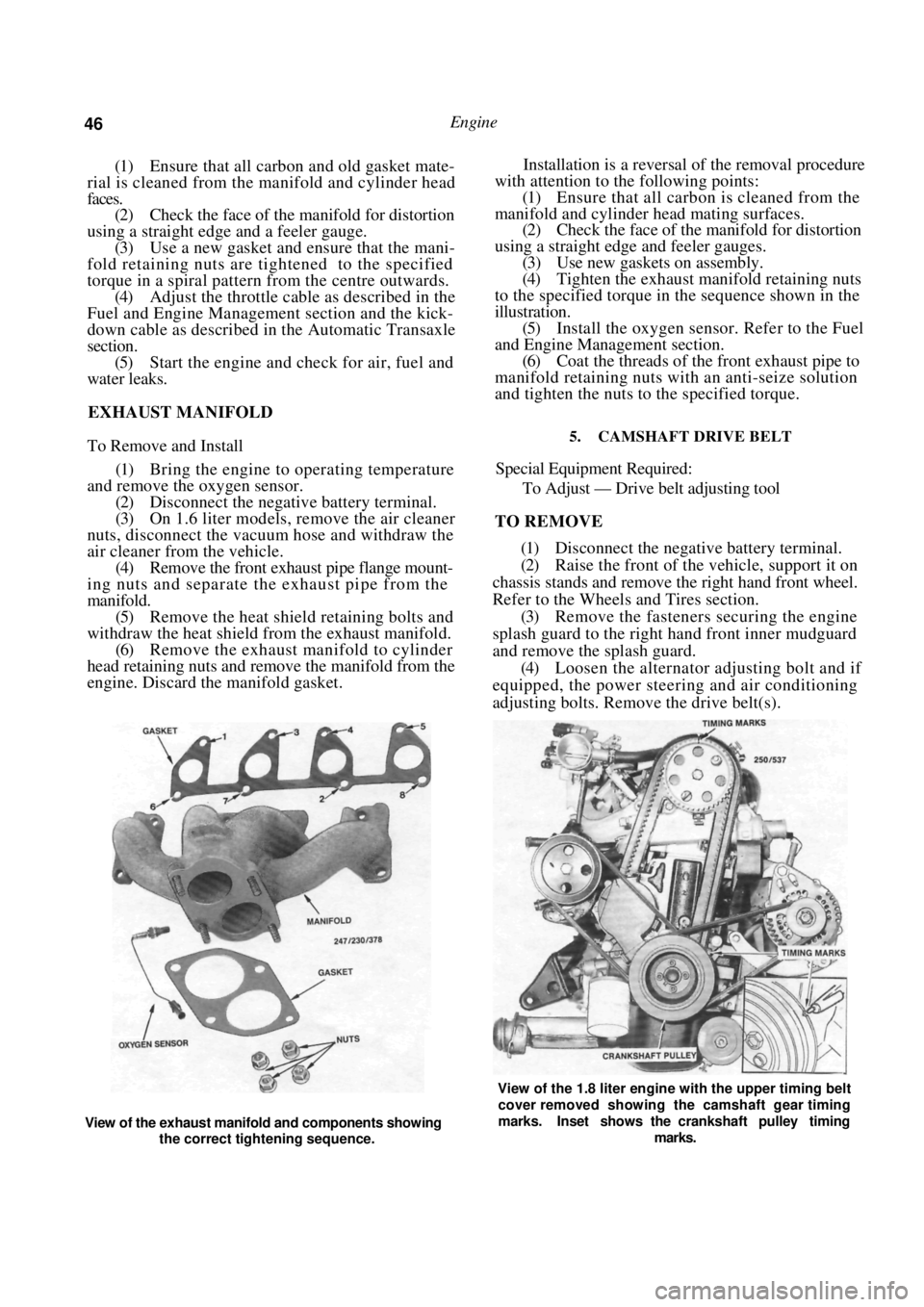
(4) Tighten the exhaust manifold retaining nuts
to the specified torque in the sequence shown in the
illustration. (5) Install the oxygen sensor. Refer to the Fuel
and Engine Management section. (6) Coat the threads of the front exhaust pipe to
manifold retaining nuts with an anti-seize solution
and tighten the nuts to the specified torque.
5. CAMSHAFT DRIVE BELT
Special Equipment Required:
To Adjust — Drive belt adjusting tool
TO REMOVE
(1) Disconnect the negative battery terminal.
(2) Raise the front of the vehicle, support it on
chassis stands and remove the right hand front wheel.
Refer to the Wheels and Tires section. (3) Remove the fasteners securing the engine
splash guard to the right hand front inner mudguard
and remove the splash guard. (4) Loosen the alternator adjusting bolt and if
equipped, the power steering and air conditioning
adjusting bolts. Remove the drive belt(s).
View of the exhaust manifold and components showing
the correct tightening sequence.
View of the 1.8 liter engine with the upper timing belt
cover removed showing the camshaft gear timing
marks. Inset shows the crankshaft pulley timing
marks.
Page 48 of 238
48 Engine
TO INSTAL
(1) Check that the camshaft and crankshaft
timing gears have not been moved and that the timing
marks are still aligned. It will be necessary to tempo-
rarily install the crankshaft pulley to check that the
timing marks are still aligned. (2) Install the drive belt to the crankshaft timing
gear around the water pump gear and onto the
camshaft timing gear.
NOTE: If the original drive belt is being
installed, ensure that the arrow marked on
the belt prior to removal is pointing in the
direction of rotation.
(3) Use the adjusting tool to turn the water
pump assembly sufficiently to engage the water pump
pulley with the drive belt. (4) Install the inner cover lower retaining bolt.
(5) Ensure that the drive be lt is correctly meshed
with the teeth of the camshaft, crankshaft and water
pump gears. Install the crankshaft pulley and tighten
the bolts to Specifications. (6) Adjust the drive belt as described under the
following heading.
(7) Install the drive belt outer cover and fasten
the retaining clips. (8) Install and adjust the alternator and if
equipped, the power steeri ng and air conditioning
drive belts as desc ribed in the Engine Tune-up section.
TO ADJUST
(1) Remove the alternator drive belt and if
equipped, the power steering and air conditioning
drive belts. (2) Release the clips securing the camshaft drive
belt outer cover to the inner cover and remove the
outer cover. (3) Turn the engine in the direction of rotation
until the timing marks on the camshaft and the inner
cover are aligned. (4) Loosen the water pump retaining bolts and
using the adjusting tool, rotate the water pump
housing to gain the required belt tension. The belt is
correctly tensioned when it can be grasped between
the thumb and forefinger midway between the cam-
shaft timing gear and the water pump gear and turned
ninety degrees from i t s operating position.
After the belt has been tensioned, tighten the
water pump retaining bolts to the specified torque.
NOTE: Over tensioning of the drive belt will
result in noisy operation and premature
wear of the belt.
(6) Install the outer drive belt cover.
(7) Install and adjust the alternator, and if
equipped, the power steering and air conditioning
drive belts as desc ribed in the Engine Tune-up section. 6. CAMSHAFT. ROCKER ARMS AND TAPPETS
Special Equipment Required:
To Check Camshaft — Dial gauge, Vee blocks and
micrometers
To Install — Drive belt adjusting tool
It is recommended that a new cylinder head
gasket is installed and the cylinder head bolts renewed
when the camshaft housing is removed.
TO REMOVE
(1) Disconnect the negative battery terminal.
Remove the nuts securing the earth wires to the
cylinder head bolts and remove the earth wires.
(2) On 1.6 liter models, remove the air cleaner
wingnuts and withdraw the air cleaner.
(3) Disconnect the engine breather hoses from
the camshaft housing and the camshaft housing top
cover. (4) Remove the camshaft housing top cover
retaining bolts and remove the top cover. Discard the
gasket.
(5) Remove the camshaft dr ive belt as described
under the previous heading. (6) Using an open ended spanner, hold the
camshaft between the inle t and exhaust lobes of
number four cylinder and remove the camshaft timing
gear retaining bolt and the camshaft timing gear.
(7) Remove the distributor, distributor cap and
high tension leads. If necessary refer to the Fuel and
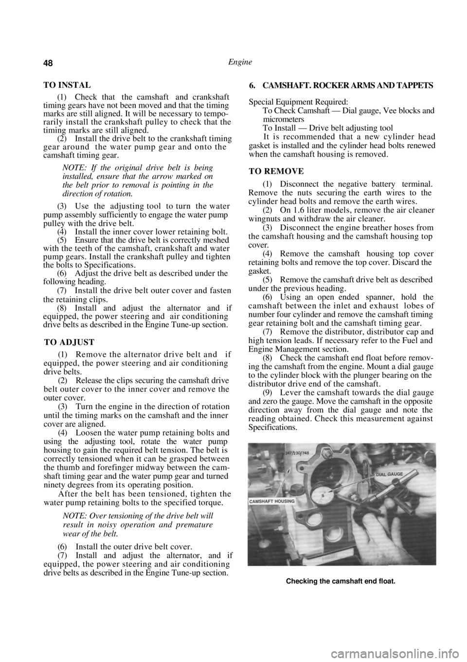
Engine Management section. (8) Check the camshaft end float before remov-
ing the camshaft from the engine. Mount a dial gauge
to the cylinder block with the plunger bearing on the
distributor drive end of the camshaft. (9) Lever the camshaft towards the dial gauge
and zero the gauge. Move the camshaft in the opposite
direction away from the dial gauge and note the
reading obtained. Check this measurement against
Specifications.
Checking the camshaft end float.