spare wheel NISSAN PULSAR 1987 Workshop Manual
[x] Cancel search | Manufacturer: NISSAN, Model Year: 1987, Model line: PULSAR, Model: NISSAN PULSAR 1987Pages: 238, PDF Size: 28.91 MB
Page 7 of 238
VEHICLE IDENTIFICATION AND GENERAL SPECIFICATIONS
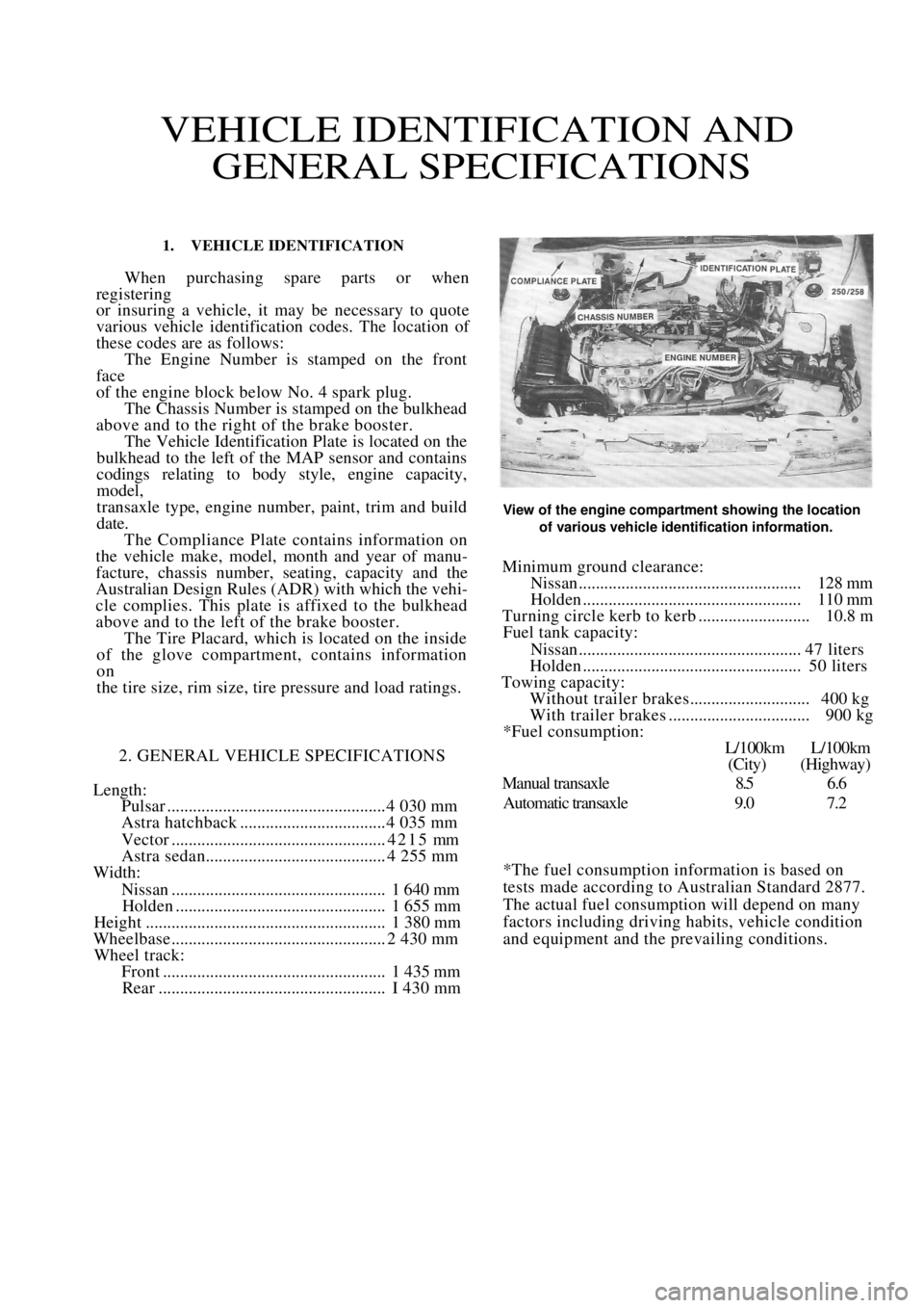
1. VEHICLE IDENTIFICATION
When purchasing spare parts or when
registering
or insuring a vehicle, it may be necessary to quote
various vehicle identification codes. The location of
these codes are as follows: The Engine Number is stamped on the front
face
of the engine block below No. 4 spark plug. The Chassis Number is stamped on the bulkhead
above and to the right of the brake booster. The Vehicle Identification Plate is located on the
bulkhead to the left of the MAP sensor and contains
codings relating to body style, engine capacity,
model,
transaxle type, engine number, paint, trim and build
date. The Compliance Plate contains information on
the vehicle make, model, month and year of manu-
facture, chassis number, seating, capacity and the
Australian Design Rules (ADR) with which the vehi-
cle complies. This plate is affixed to the bulkhead
above and to the left of the brake booster. The Tire Placard, which is located on the inside
of the glove compartment, contains information
on
the tire size, rim size, tire pressure and load ratings.
2. GENERAL VEHICLE SPECIFICATIONS
Length:
Pulsar ................................................... 4 030 mm
Astra hatchback .................................. 4 035 mm
Vector ..................................................4215 mm
Astra sedan.......................................... 4 255 mm
Width:
Nissan.................................................. 1 640 mm
Holden ................................................. 1 655 mm
Height ........................................................ 1 380 mm
Wheelbase .................................................. 2 430 mm
Wheel track:
Front .................................................... 1 435 mm
Rear ..................................................... I 430 mm
View of the engine compartment showing the location
of various vehicle identification information.
Minimum ground clearance:
Nissan.................................................... 128 mm
Holden ................................................... 110 mm
Turning circle kerb to kerb .......................... 10.8 m
Fuel tank capacity:
Nissan.................................................... 47 liters
Holden ................................................... 50 liters
Towing capacity:
Without trailer brakes............................ 400 kg
With trailer brakes ................................. 900 kg
*Fuel consumption:
L/100km L/100km
(City) (Highway)
Manual transaxle 8.5 6.6
Automatic transaxle 9.0 7.2
*The fuel consumption information is based on
tests made according to Australian Standard 2877.
The actual fuel consumption will depend on many
factors including driving habits, vehicle condition
and equipment and the prevailing conditions.
Page 21 of 238
WHEELS AND TYRES
SPECIFICATIONS
TYRES PRESSURES
Front:
Normal load ............................................ 200 kPa
Heavy load or high speed ......................230 kPa
Rear:
Normal load............................................ 180 kPa
Heavy load or high speed ...................... 210 kPa
NOTE: The above pressures are measured
cold and are meant as a guide only. Always
refer to the tire placard positioned on the
inside of the glove compartment lid and the
tire manufacturers recommendations first.
TORQUE WRENCH SETTINGS
Wheel nut torque .............................................98 Nm
1. HOW TO CHANGE A ROAD WHEEL
(1) Ensure that the vehicle is on level firm
ground and clear of any passing traffic. (2) If necessary, switch on the hazard
flashers.
(3) Switch off the engine a nd place the transaxle
in the (P) Park position on automatic transaxle
models or in reverse gear on manual transaxle models.
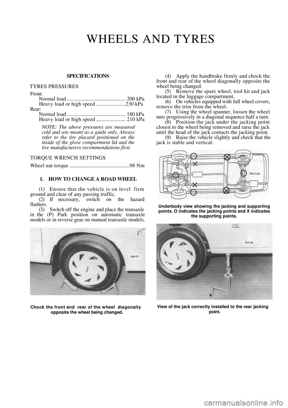
(4) Apply the handbrake firmly and chock the
front and rear of the wheel diagonally opposite the
wheel being changed.
(5) Remove the spare wheel, tool kit and jack
located in the luggage compartment. (6) On vehicles equipped with full wheel covers,
remove the trim from the wheel. (7) Using the wheel spanner, loosen the wheel
nuts progressively in a diagonal sequence half a turn.
(8) Position the jack und er the jacking point
closest to the wheel being removed and raise the jack
until the head of the jack contacts the jacking point.
(9) Raise the vehicle slightly and check that the
jack is stable and vertical.
Underbody view showing the jacking and supporting
points. O indicates the jacking points and X indicates
the supporting points.
Chock the front and rear of the wheel diagonally
opposite the wheel being changed. View of the jack correctly installed to the rear jacking
point.
Page 22 of 238
22 Wheels and Tires
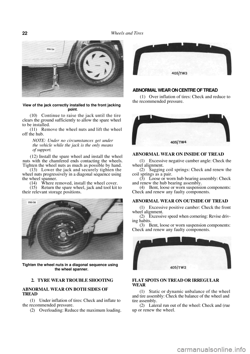
View of the jack correctly installed to the front jacking point
.
(10) Continue to raise the jack until the tire
clears the ground sufficiently to allow the spare wheel
to be installed.
(11) Remove the wheel nuts and lift the wheel
off the hub.
NOTE: Under no circumstances get under
the vehicle while the jack is the only means
of support.
(12) Install the spare wh eel and install the wheel
nuts with the chamfered e nds contacting the wheels.
Tighten the wheel nuts as much as possible by hand.
(13) Lower the jack and securely tighten the
wheel nuts progressively in a diagonal sequence using
the wheel spanner. (14) Where removed, install the wheel cover.
(15) Return the spare wheel, jack and tool kit to
their relevant storage positions.
ABNORMAL WEAR ON CENTRE OF TREAD
(1) Over inflation of tires: Check and reduce to
the recommended pressure.
ABNORMAL WEAR ON INSIDE OF TREAD
(1) Excessive negative camber angle: Check the
wheel alignment. (2) Sagging coil springs: Check and renew the
coil springs as a pair. (3) Loose or worn hub bearing assembly: Check
and renew the hub bearing assembly. (4) Bent, loose or worn suspension components:
Check and renew any faulty components.
ABNORMAL WEAR ON OUTSIDE OF TREAD
(1) Excessive positive camber: Check the front
wheel alignment.
(2) Excessive speed when cornering: Revise driv-
ing habits. (3) Bent, loose or worn suspension components:
Check and renew any faulty components.
2. TYRE WEAR TROUBLE SHOOTING
ABNORMAL WEAR ON BOTH SIDES OF
TREAD
(1) Under inflation of tires: Check and inflate to
the recommended pressure.
(2) Overloading: Reduce the maximum loading. FLAT SPOTS ON TREAD OR IRREGULAR
WEAR
(1)
Static or dynamic unbalance of the wheel
and tire assembly: Check the balance of the wheel and
tire assembly. (2) Lateral run out of the wheel: Check and (rue
up or renew the wheel.
Tighten the wheel nuts in a diagonal sequence using
the wheel spanner.
Page 24 of 238
24 Wheels and Tires
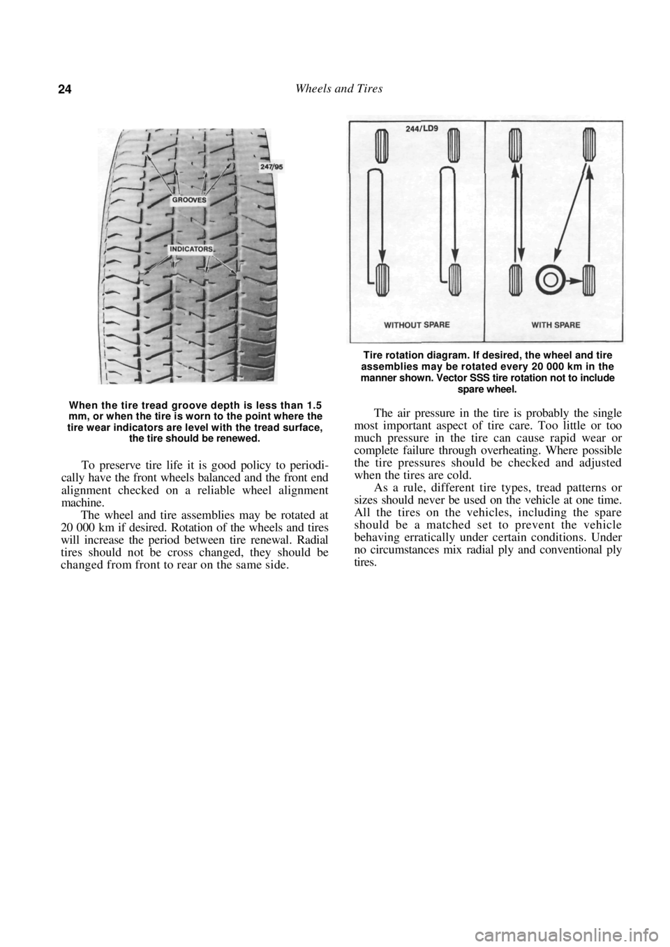
When the tire tread groove depth is less than 1.5
mm, or when the tire is worn to the point where the
tire wear indicators are level with the tread surface,
the tire should be renewed.
To preserve tire life it is good policy to periodi-
cally have the front wheels balanced and the front end
alignment checked on a reliable wheel alignment
machine.
The wheel and tire assemblies may be rotated at
20 000 km if desired. Rotation of the wheels and tires
will increase the period between tire renewal. Radial
tires should not be cross changed, they should be
changed from front to rear on the same side.
Tire rotation diagram. If desired, the wheel and tire
assemblies may be rotated every 20 000 km in the
manner shown. Vector SSS tire rotation not to include
spare wheel.
The air pressure in the tire is probably the single
most important aspect of tire care. Too little or too
much pressure in the tire can cause rapid wear or
complete failure through overheating. Where possible
the tire pressures should be checked and adjusted
when the tires are cold.
As a rule, different tire types, tread patterns or
sizes should never be used on the vehicle at one time.
All the tires on the vehicles, including the spare
should be a matched set to prevent the vehicle
behaving erratically under certain conditions. Under
no circumstances mix radial ply and conventional ply
tires.
Page 188 of 238
188 Brakes
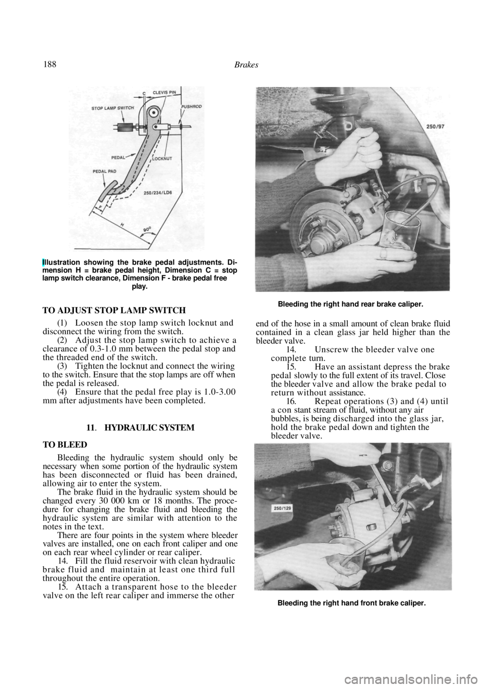
Illustration showing the brake pedal adjustments. Di-
mension H = brake pedal height, Dimension C = stop
lamp switch clearance, Dimension F - brake pedal free
play.
TO ADJUST STOP LAMP SWITCH
(1) Loosen the stop lamp switch locknut and
disconnect the wiring from the switch.
(2) Adjust the stop lamp switch to achieve a
clearance of 0.3-1.0 mm between the pedal stop and
the threaded end of the switch. (3) Tighten the locknut and connect the wiring
to the switch. Ensure that the stop lamps are off when
the pedal is released.
(4) Ensure that the pedal free play is 1.0-3.00
mm after adjustments have been completed.
11. HYDRAULIC SYSTEM
TO BLEED
Bleeding the hydraulic system should only be
necessary when some portion of the hydraulic system
has been disconnected or fluid has been drained,
allowing air to enter the system.
The brake fluid in the hydraulic system should be
changed every 30 000 km or 18 months. The proce-
dure for changing the brake fluid and bleeding the
hydraulic system are simila r with attention to the
notes in the text.
There are four points in the system where bleeder
valves are installed, one on each front caliper and one
on each rear wheel cylinder or rear caliper.
14. Fill the fluid reservoir with clean hydraulic
brake fluid and maintain at least one third full
throughout the entire operation. 15. Attach a transparent hose to the bleeder
valve on the left rear cali per and immerse the other
Bleeding the right hand rear brake caliper.
end of the hose in a small amount of clean brake fluid
contained in a clean glass jar held higher than the
bleeder valve.
14. Unscrew the bleeder valve one
complete turn.
15. Have an assistant depress the brake
pedal slowly to the full extent of its travel. Close
the bleeder valve and allow the brake pedal to
r e t u r n w i t h o u t assistance. 16. Repeat operations (3) and (4) until
a con stant stream of fluid, without any air
bubbles, is being discharged into the gl ass jar,
hold the brake pedal down and tighten the
bleeder valve.
Bleeding the right hand front brake caliper.